Week 11 - Final project
AIM:
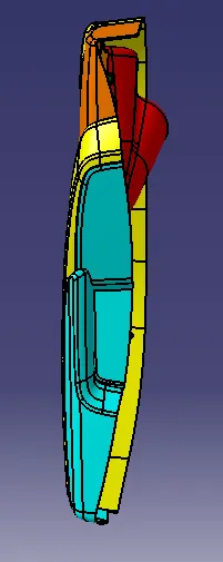
Develop a Door Trim panel and Create mounting features as per design guidelines in the industry and with master sections, dog house and push pin for the door trim panel considering the design rules.
OBJECTIVE:
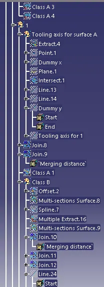
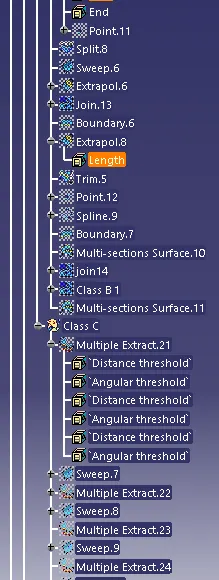
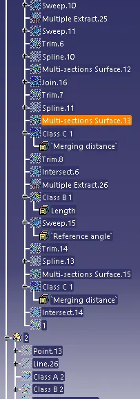
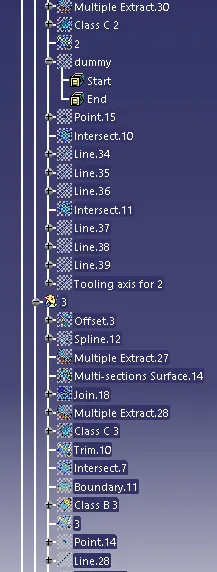
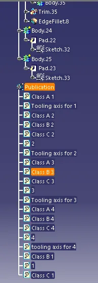
- Ensure Proper Tree Structure
- Geometrical sets should have a proper name based on the sketches present inside of it
- All the sketches should be created under the Geometrical set
- A detailed report should be done explaining the draft analysis and the tooling axis creation.
- An explanation should be given on the way of creating the tooling axis particularly the Bisecting method.
PROCEDURE:
Step-1: Connectivity check
Arm rest
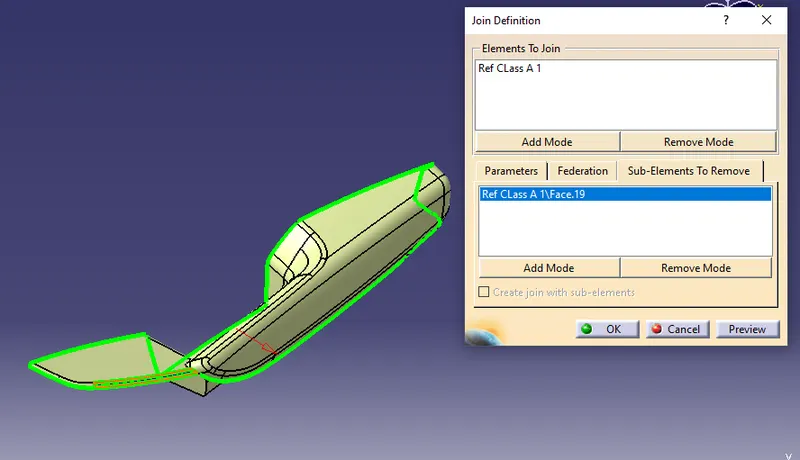
- First we have to verify the part design using join surface option by simply selecting the class A surface .
- Another method is create a boundary layer of surface and disassemble it from the boundary layer from the surface.
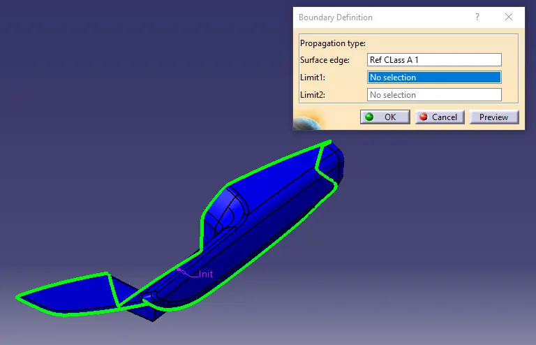
- Since the boundary has excess lines inside it.
- Or create spline and use multi-sections surfaces option to join the removed sub-element and again join.
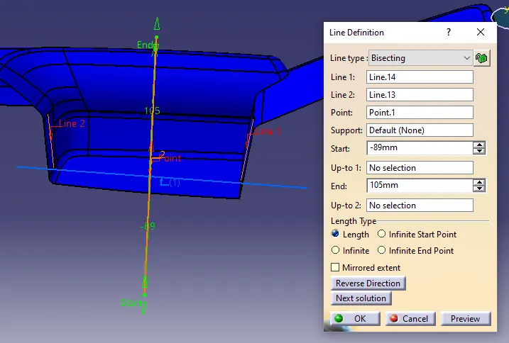
Step-2: Create tooling axis (Bisecting method)
- Create a reference point by selecting the center circle of surface.
- Then create the axis for the surface to easily define the tooling axis.
- simply select the point and xyz plane.
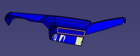
- To get a dummy tooling axis in x direction.
- Use the intersection command, to get a wire diagram of surface in x direction.
- Use multiple extract to separate the bottom face for tooling axis definition.
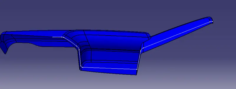
- select the intersection command, select first element is plane of dummy axis say zx plane, select second element as class A surface, click ok.
- The draft angle of x direction is created to get the tooling axis of x-direction.
- We will get the tooling axis in x-direction and also define its line color and thickness
- After the dummy axis definition, select the tooling axis of x to bisect using line command.
- The tooling axis for draft analysis is formed.
- Use publication command to publish the class A surface and tooling axis.
Step-3: Perform draft analysis
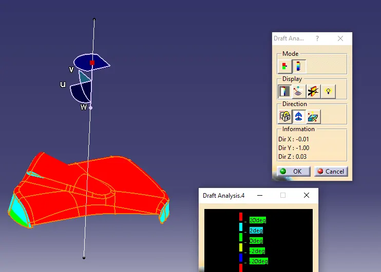
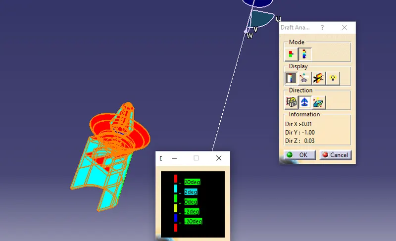
- Select the draft analysis command, ensure the material feature is used.
- Use quick analysis mode, display color scale option.
- Click on compass command on direction, drag and drop it in tooling axis.
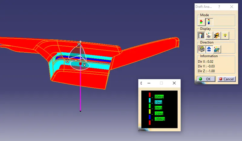
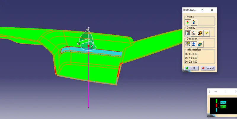
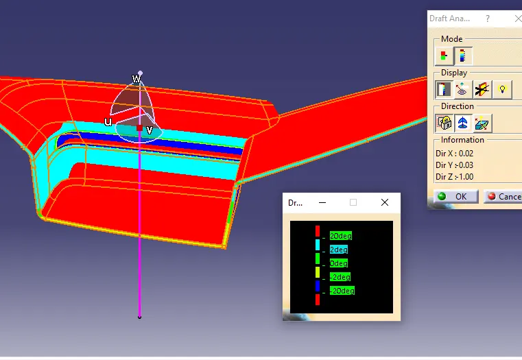
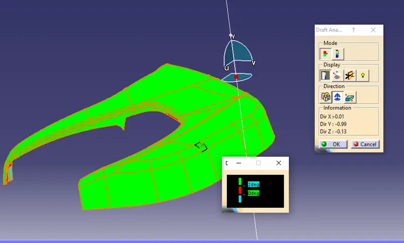
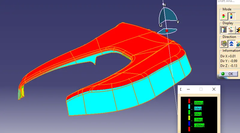
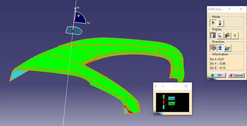
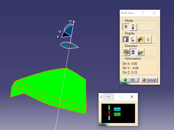
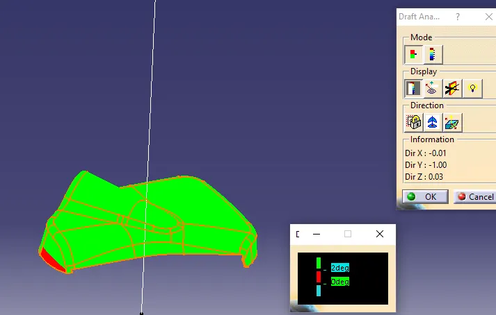
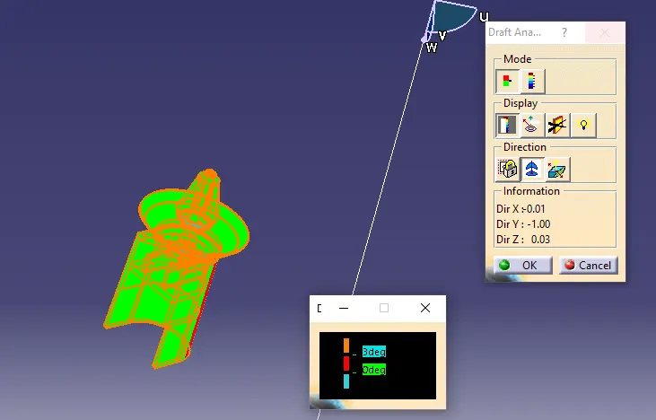
- The draft should show green surface which is feasible draft angle.
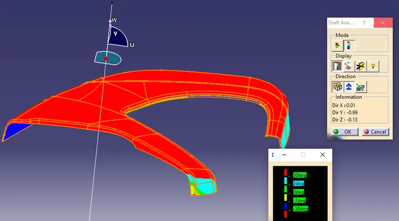
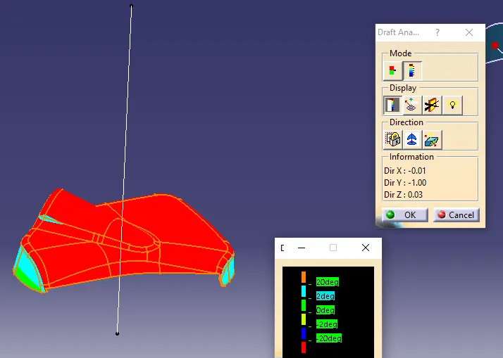
- If red is shown not feassible draft angle and for blue negative draft angle.
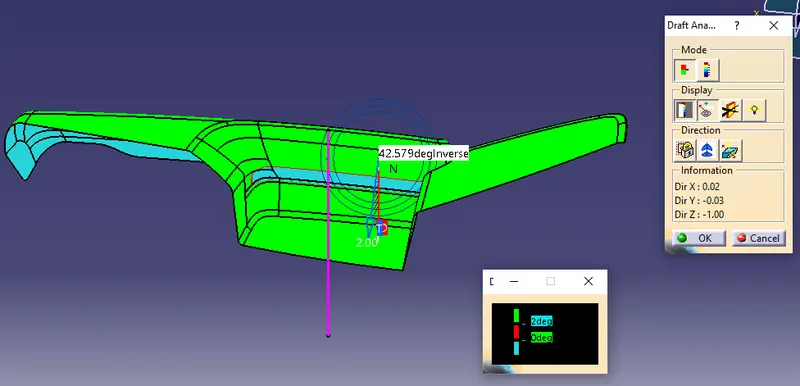
- Use analyses under running point, to ensure same angle on symmetrical direction.
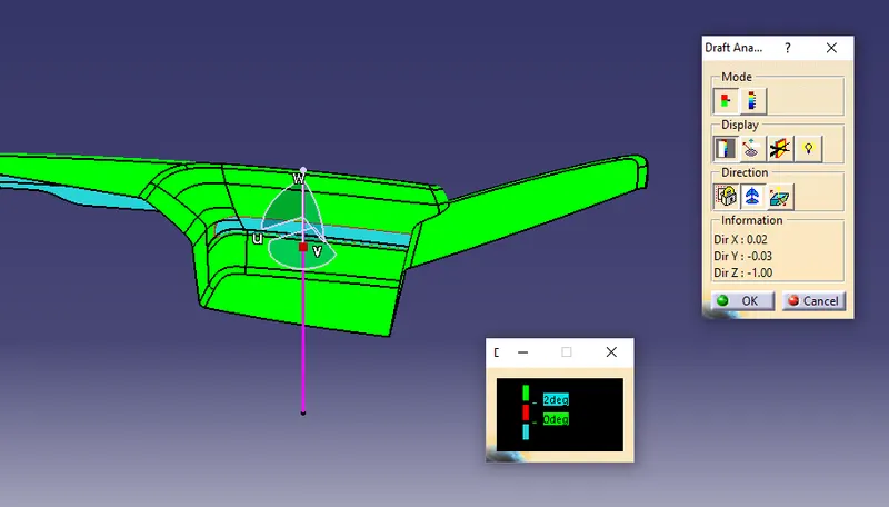
- Below is fully analyze mode to get the varied angle in class A surface.
- Below is fully analyze mode to get the varied angle in class C surface.
Lower substrate
class A surface
Solid surface
Lower Map pocket
class A surface
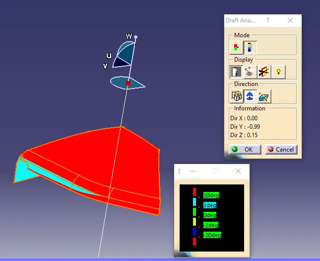
Solid surface
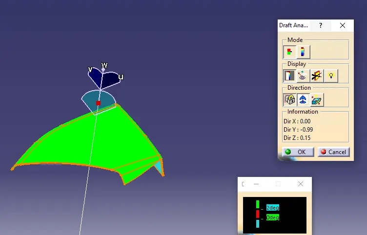
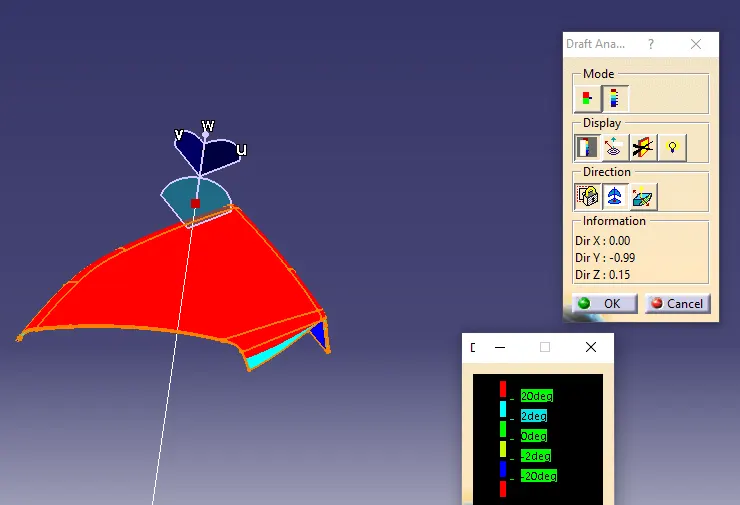
Map pocket
class A surface
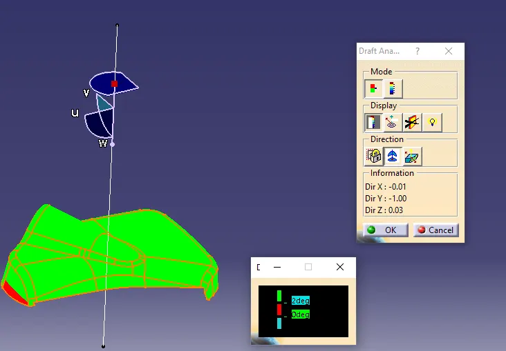
Solid surface
Heat stakes and push pin
Step-4: Create class B surface
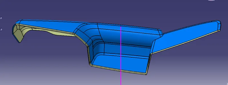
- Offset the trimmed surafce from 2.5mm.
Step-5: Create class C surface
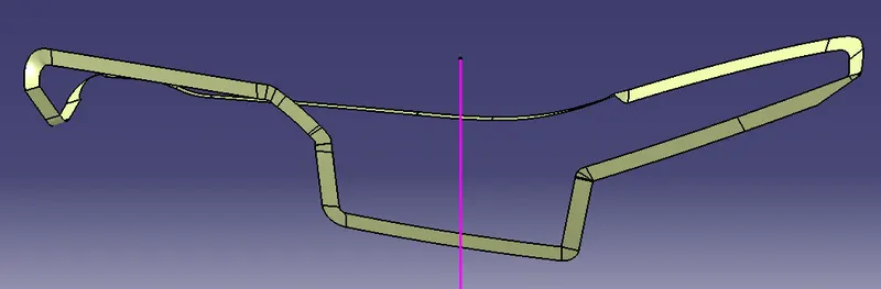
- Do same procedure to creaate the class c surface from the top and bottom of the class A surface.
- And trim the side and top surfaces together.
Step-6: Join the surfaces together
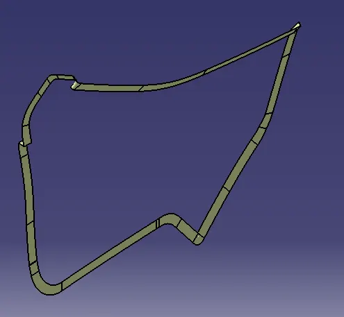
- First creaet intersect of class C surface and B surface.
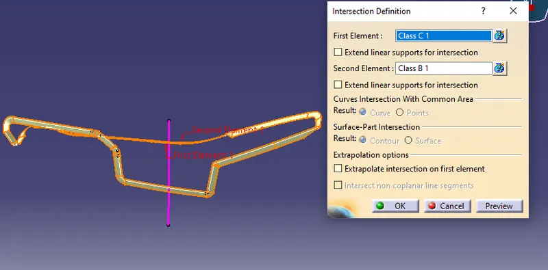
- Then click the sweep option to select profile type line, draft doirection, guide curve as boundary layer and draft direction as tooling axis.
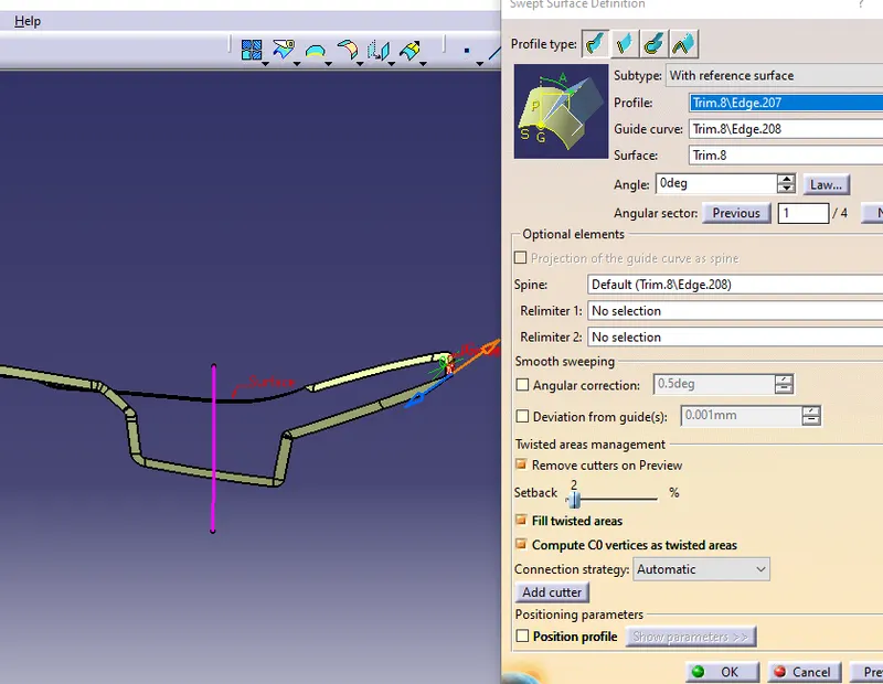
- Follow the same procedure to attain the top layer and 2 holes.
- Then join the side sweep and top sweep togther and 2 holes as well.
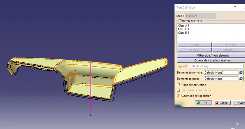
- Finally trim the joined surfaces and class C surface to get the final result.
- Also do the same process for other parts and make them as closed surfaces.
Lower substrate
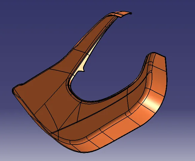
Class A surface
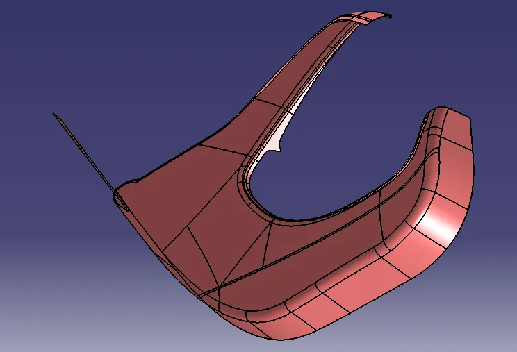
Class B surface
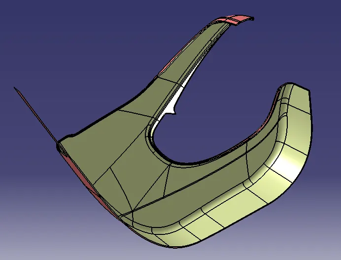
Class C surface
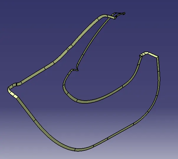
Lower Map pocket
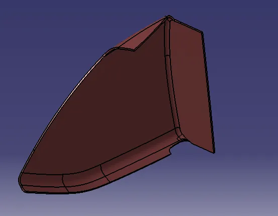
Class A surface
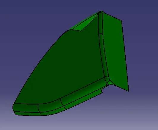
Class B surface
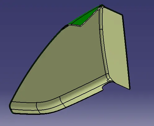
Class C surface
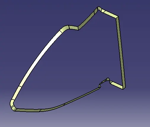
Map pocket
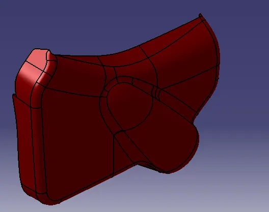
Class A surface
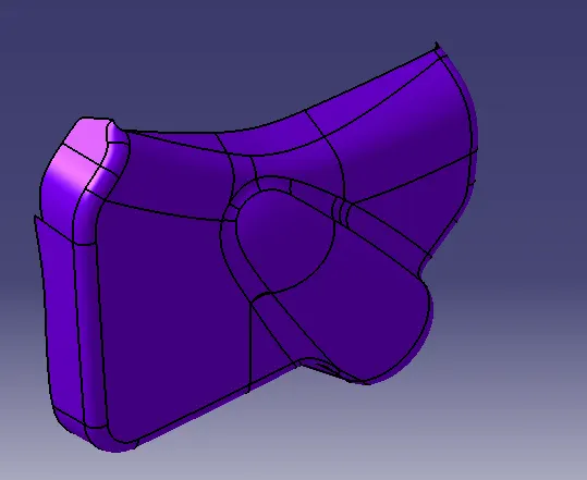
Class B surface
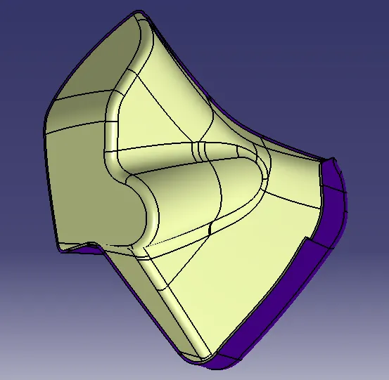
Class C surface
Step-7: Create heat stakes
- Then create a sketch of a line which is heat stakes baseline and constraints should apply.
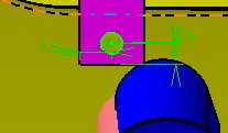
- Also extended the other side by upto the surface option or else the object can't be assembled.
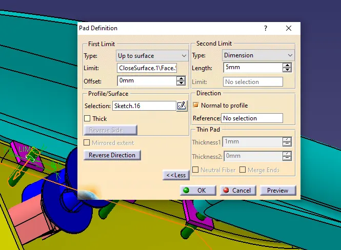
- Also translate the heat stakes to the developed boundary of flange.
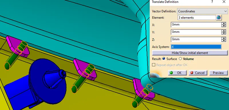
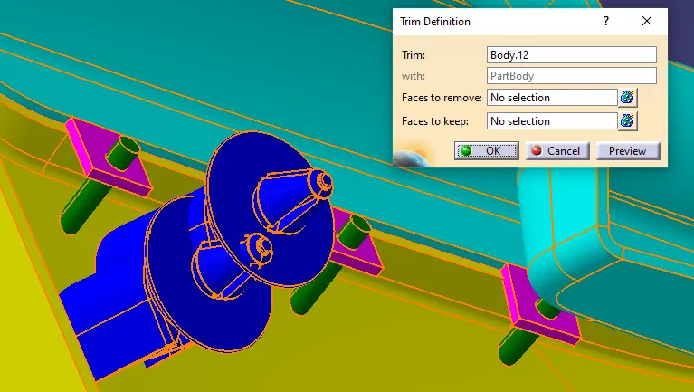
- Create a body and use boolean assemble option.
Step-8: Create attachment allowances as flanges
- Then create a sketch of a line which is flanges baseline and constraints should apply.
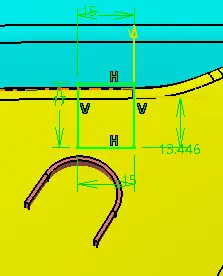
- Also extended the other side for 2.5 mm or else the object can't be assembled.
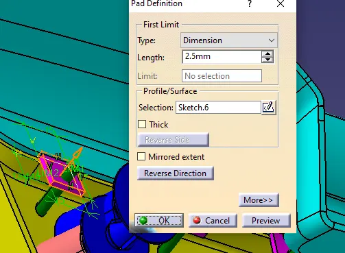
- Also translate the flanges attachement allowanances on the boundary.
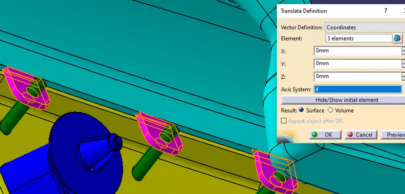
- And also apply edge fillet as 0.25 mm.
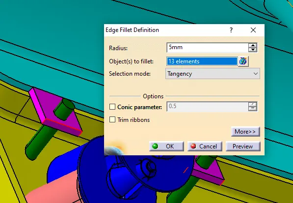
- Create a body and use boolean assemble option.
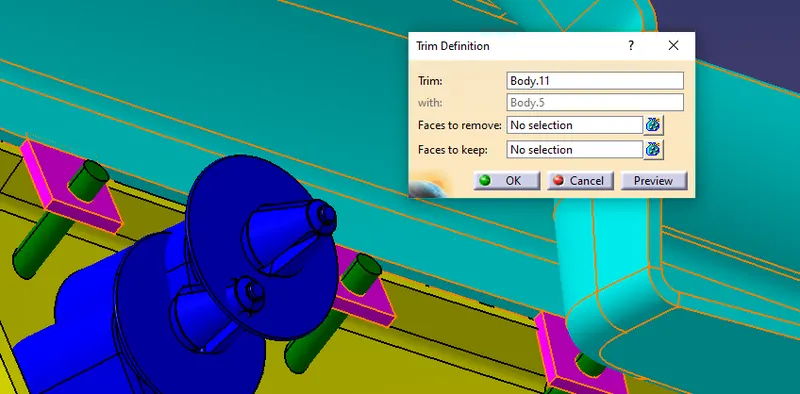
Step-9: Create dog house
- Create a sketch of a line which is dog house baseline and constraints should apply.
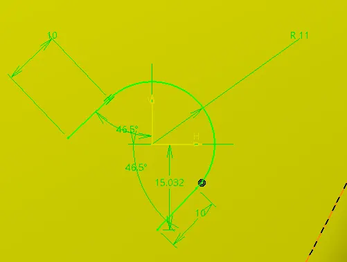
- Sweep the line for 5t where t is thickness of the object (2.5mm).
- Also extended the other side for 1 mm or else the object can't be assembled.
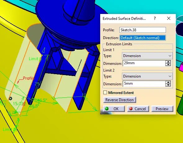
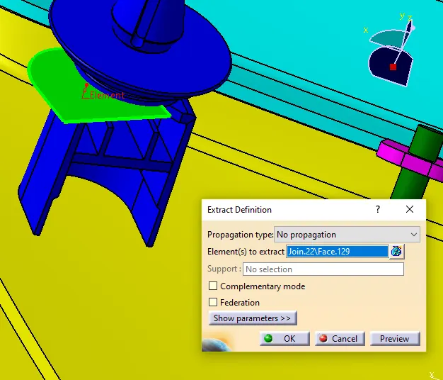
- Extract and untrim the bottom part of console.
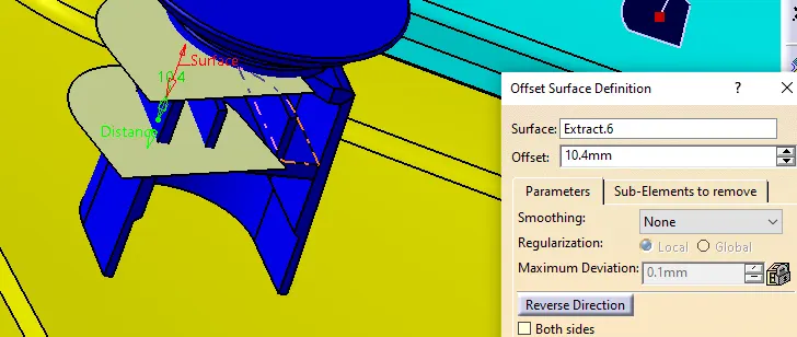
- And offset it to close the swept dog house baseline and trim it.
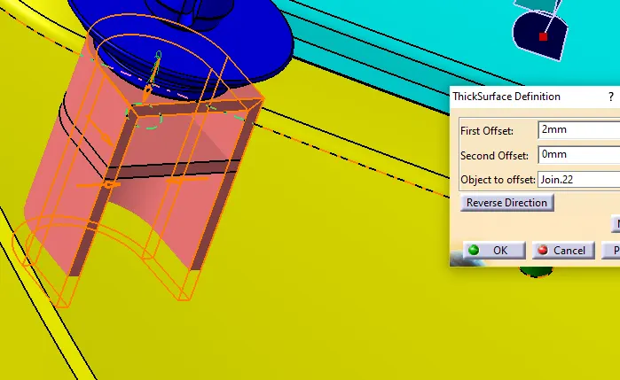
- Use the thick surface option.
- Extract and untrim the middle part of dog house.
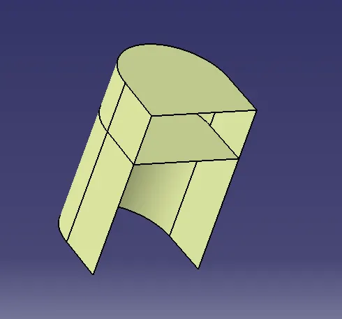
- Extract and explorate the inner part of dog house and push pin.
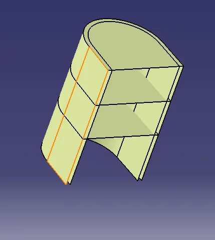
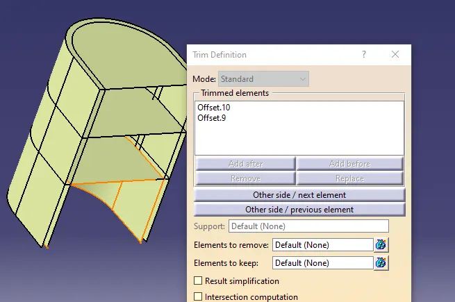
- And offset the base plane to trim the inner wall of intersection to dog house and push pin.
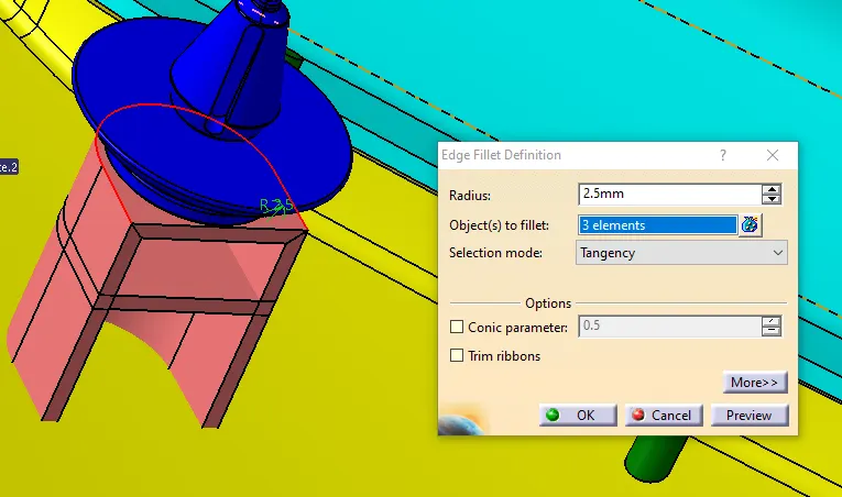
- And also apply edge fillet as 0.25 mm.
- Create a body and use boolean assemble option.
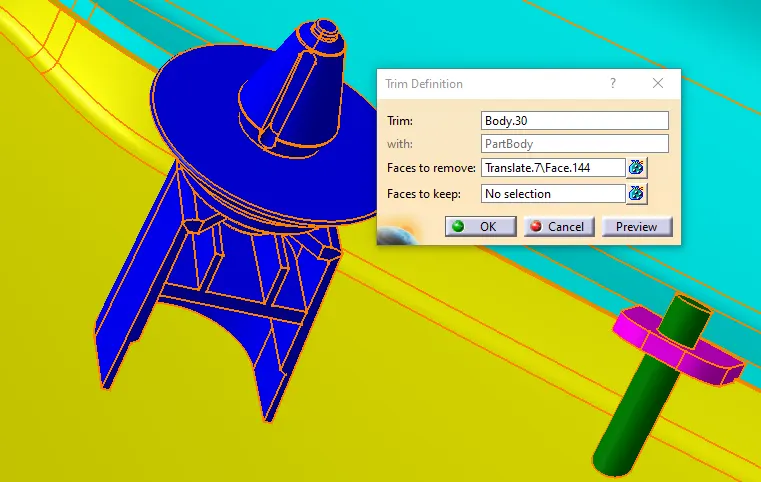
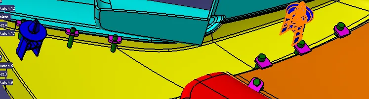
- Use Translate or pattern option to move the boss to bottom and right side of lower substrate.
Step-10: Create push pins
- Create a sketch of a line which is dog house baseline and constraints should apply.
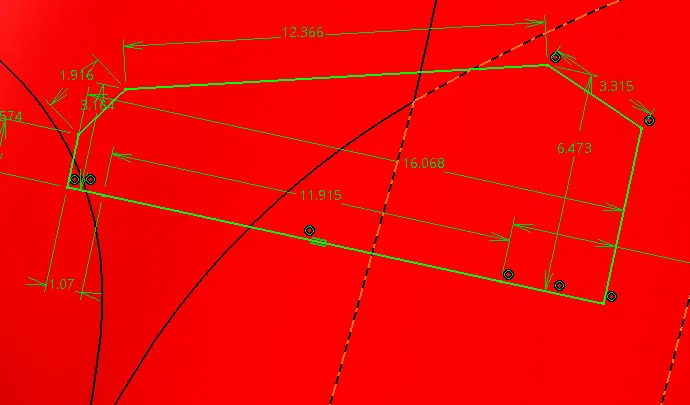
- Then use shaft option to rotate the push pin sketch.
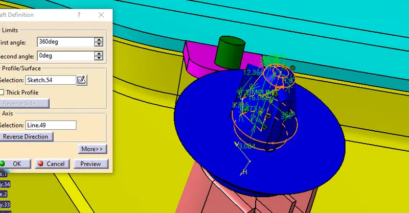
- The push pin has a grooved surface at top surface create its sketch.
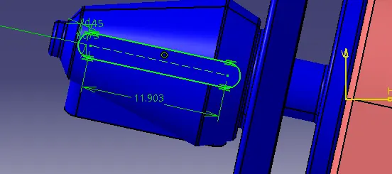
- And groove the surface.
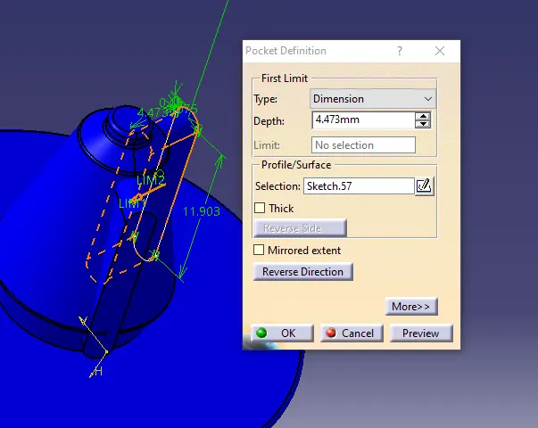
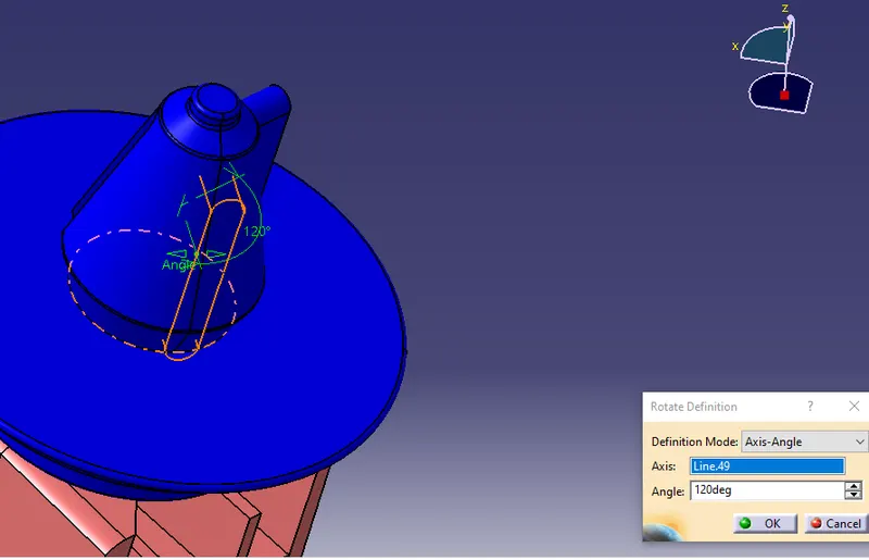
- Also rotate the grooved surface for 120 and 240 deg.
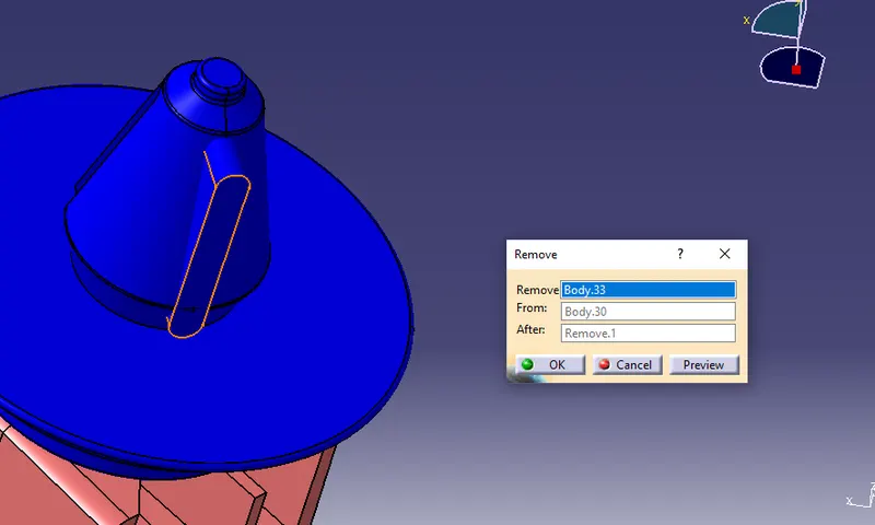
- Create boolean operation to remove the grooves.
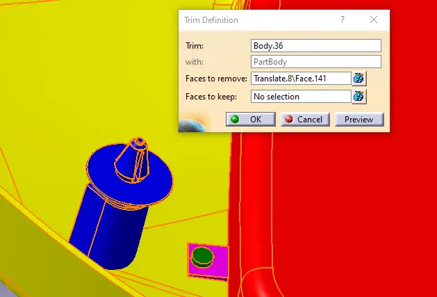
- Create boolean operations to assemble the push pin to heat stakes.
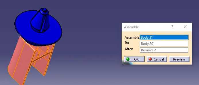
- Also create the boolean union trim to the part body.
RESULT:
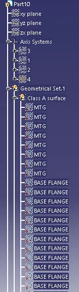
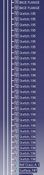
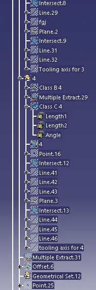
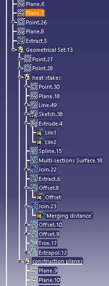
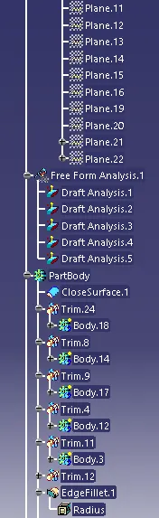
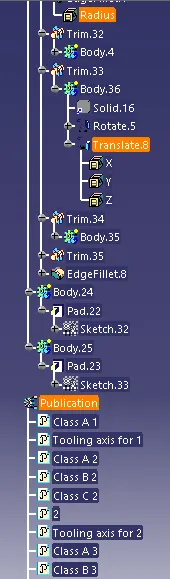
- Tree structure
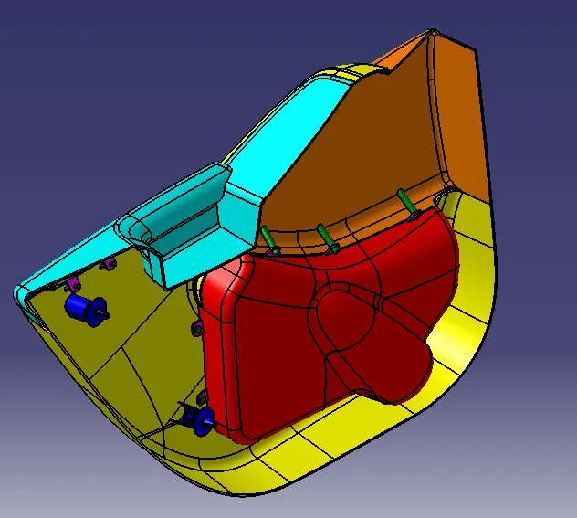
- Isometric View
- Front View
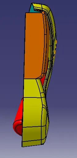
- Side View
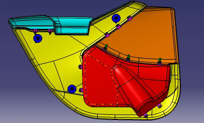
- Top View