Week 11 - Final project
DOOR TRIM PANEL
AIM
- To create a CAD model DOOR TRIM PANEL considering Class A Surface, Nominal Thickness, and Attachment Features.
OBJECTIVE
- Create thickened parts using the master section for reference.
- Create the mounting features as per design guidelines in the industry and with master sections.
- Apply material details.
- Draft analysis & Tooling analysis.
INTRODUCTION
- CATIA stands for Computer-Aided Three-Dimensional Interactive Application. It's much more than a CAD (Computer-Aided Design) software package. It's a full software suite that incorporates CAD, CAE (Computer-Aided Engineering), and CAM (Computer-Aided Manufacture).
- New Product Design describes the process of imagining, creating, and iterating products that solve users' problems or address specific needs in a given market. The key to successful product design is an understanding of the end-user customer, the person for whom the product is being created.
- Create a CAD model of DOOR TRIM PANEL considering Class A Surface, Nominal Thickness, and Attachment Features.
DOOR PANEL
- Door panels serve as an interface between the interior of the car and the inner workings of the door, and between vehicle occupants and the door. They are expected to meet a variety of design specifications regarding safety, aesthetics, and functionality. In addition, they are expected to continue the material theme of the dashboard and pillars while concealing intricate electrical and mechanical components for operating locks, windows, and other features. The door panel has evolved from a simple two-part system of the latch and simple winding mechanism to a more sophisticated enclosure. Doors currently have an inner full-width panel consisting of electronic windows, a central locking system, and speakers. These panels typically consist of a foamed core covered with either textiles or plastics
10 STAGES OF PRODUCT LIFE CYCLE OF AUTOMOTIVE INDUSTRY
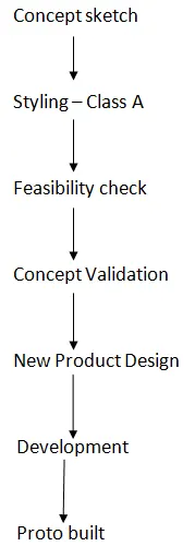
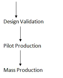
Concept Sketch
- It is freehand sketching in the paper later fed into the computer to create a styling surface.
Styling - Class A
- Styling is a design from a concept sketch.
- All the concept sketches are not one-to-one matched in styling.
- There can be few alterations, the concept sketch gets evolved into different shapes.
- Styling is done in software called ALIAS.
Feasibility Check
- A feasibility check is an assessment of the practicality of a proposed plan or method.
- It is the study of requirements, evaluation of the alternatives, and agreed-upon course of action.
Concept Validation
- In concept validation, we test if a particular product or service concept is interesting, inviting and functional for the client.
- Example: Safety check, visibility check, crash test, etc.
New Product Design
- In product design, we have to develop the concept.
- Ensure that the component is designed for manufacturing and assembly.
- Design a component that can be manufactured.
Development
- Development act as a bridge between design and manufacturing.
- Development works with a toolmaker, designer, a mold expert and comes up with a prototype.
Proto Built
- It is an early sample, model, or release of a product built to test a concept or process.
Design Validation
- It is a testing process by which prove ("validate") that the device you've built works for the end-user as intended.
- The purpose of design validation is to prove you designed the right device.
- No more modification is accepted after validation.
Pilot Production
- It is a manufacturing or engineering production line set up during development, to test new methods, processes, and systems.
Mass Production
- Mass production is also known as flow production or continuous production.
- It is the production of large amounts of standardizing products in a constant flow, including and especially on assembly lines.
- Class A surface extraction.
- Creation of Tooling axis and side core axis.
- Creating Class B surface.
- Creation of Class C surface.
- Joining Class A and Class C surface.
- Trimming Class B from the joined Class A and C surface.
- Forming a Closed Body.
- Check for gaps using the Boundary option.
- Forming a Solid Body.
- Creation of B side features or Attachment features.
- Performing Draft Analysis.
CLASS A SURFACE
- Class A surfaces are created on all visible exterior surfaces (ex; body panels, bumper, grille, lights, etc.) and all visible surfaces of see-touch & feel parts in the interior (ex: Dashboard, seats, door pads, etc.)
- Class A surface means visible surface.
- It is an aesthetic surface.
TOOLING AXIS
- In Molding, machine arrangement is given to open the mold along a direction which is known as Tooling Direction.
- In other words, The mold is built from two separate halves (Core and Cavity) and tooling direction basically defines the direction of mold pulls apart.
- Tooling direction is known as primary direction.
CLASS B SURFACE
- Class B surface means the thickness of a part it is not visible it is inside part.
- Class B is created by extracting each wall (surface) and un-trimming and extrapolating the walls(surface), to obtain the shape by trimming the excess surfaces and offsetting it to a certain distance based on the thickness of the model, and giving fillets wherever it is necessary.
- The offset surface will be the Class B surface.
- It also consists of ribs, screw boss, heat stakes, dog house, 2 way, and 4-way locator pins.
CLASS C SURFACE
- Class C surface means Class A and Class B combined to give Class C surface.
- The surface created using the sweep option by sweeping the boundaries of Class A along the Tooling axis to connect from Class A to Class B surface is called C-surface.
DRAFT
- No parts can be ejected from the tool if it is having a 90-degree profile from its base surface.
- A small draft angle is provided to each and every area of the component in order to get easy removal of the component from the tool.
- Required in both the core and cavity for easy ejection of the finished component.
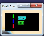
- The minimum draft angle is 3 or 2.9 degrees is used to create the Door Trim Panel.
LOWER SUBSTRATE WITH TOOLING AXIS, FLANGES, DOG HOUSE, HEAT STAKES, AND RIBS
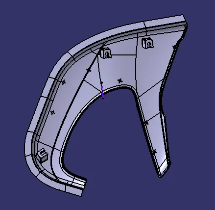
DRAFT ANALYSIS, CLASS A SURFACE OF LOWER SUBSTRATE
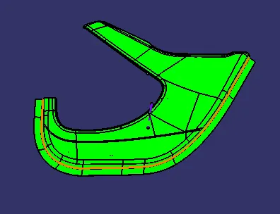
DRAFT ANALYSIS, CLASS B SURFACE OF LOWER SUBSTRATE
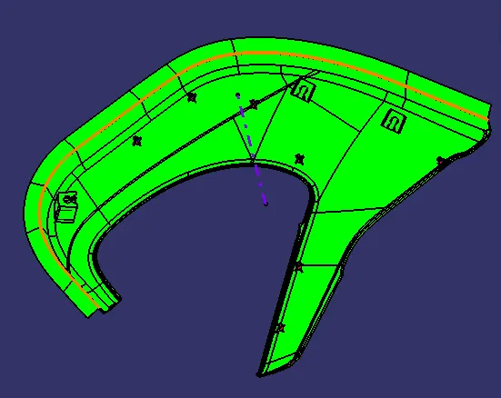
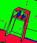
PERFORMED DRAFT ANALYSIS WITH 2.9 DEGREES
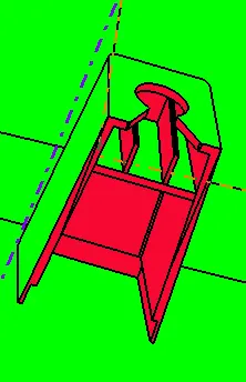
DOG HOUSE
The primary function of a dog house is to avoid sink marks on the Class A surface which may occur due to features such as a locator or rib on the Class B surface. So the best possible solution is to increase the height and decrease the cross-sectional thickness of the legs by using a dog house.
DESIGN RULES FOR DOG HOUSE
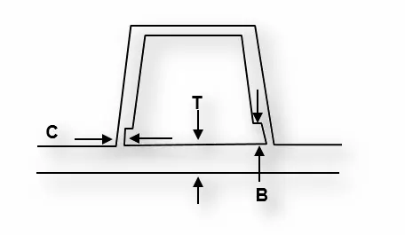
- C - The wall thickness should be less than 40% of nominal wall thickness.
- B - The height should be 3 - 6 mm from the base.
- The draft provided on the outside of the dog house should be 1.5 degrees.
- The draft provided on the inside of the dog house should be 0.5 degrees.
RIBS
-
One of the ways to strengthen a part is by adding one or more “ribs” to the design. Ribs are thin protrusions that extend perpendicular to a wall or plane to provide added stiffness and strength. Designers commonly try to increase the strength of a part by making its walls thicker. Unfortunately, walls that are too thick are subject to warpage, sinking, and other defects. The advantage of using ribs is that they increase the strength of a part without increasing the thickness of its walls. Because less material is required, ribs can be a much more cost-effective solution as well.
DESIGN RULES FOR RIBS
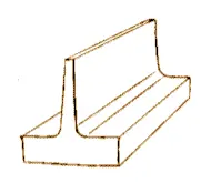
- The wall thickness should be less than 40% of nominal wall thickness.
- The height should be less than or equal to 5 times the nominal wall thickness (5*t).
- The draft angle should be 0.5 degrees per side minimum.
- The maximum thickness at the tip is 0.75 mm.
- The rib root thickness is 0.4 times the nominal thickness (0.4*t).
- The fillet radii are 0.25 maximum.
- Ribs should be connected to other structural features where possible.
HEAT STAKES
- Heat staking also known as thermoplastic staking is the process of joining two dissimilar materials together. In heat staking, we use local heating and cooling to raise the temperature of plastic components and allow plastic reforming to be carried out. This reforming can be used in a wide variety of applications.
- Applications range from staking plastic bosses for assembly of car door panels to joining PCBs to plastic housings. Benefits of this technique include; no vibration damage, no particulates, the ability to stake metalized coated applications, and the capability to stake in difficult to access or restricted areas.
DRAFT ANALYSIS WITH TOOLING AXIS OF DOG HOUSE
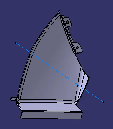
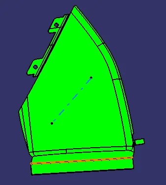
DRAFT ANALYSIS, CLASS B SURFACE OF UPPER MAP POCKET
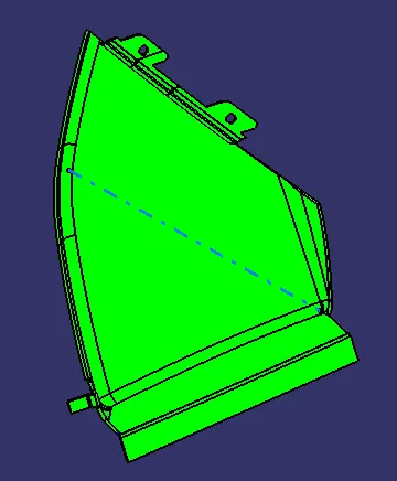
PERFORMED DRAFT ANALYSIS WITH 2.9 DEGREES
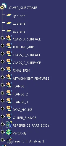
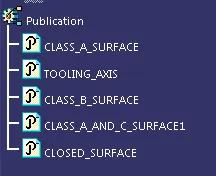
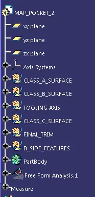
FEATURE TREE
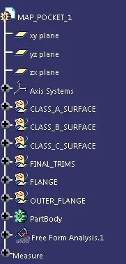
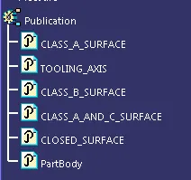
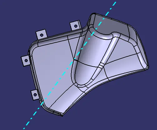
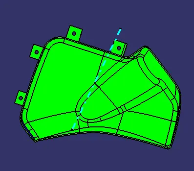
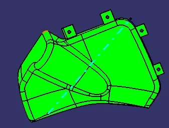
PERFORMED DRAFT ANALYSIS WITH 2.9 DEGREES
FEATURE TREE
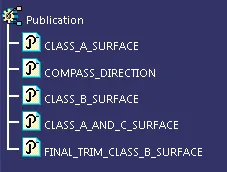
ARMREST WITH TOOLING AXIS AND FLANGES
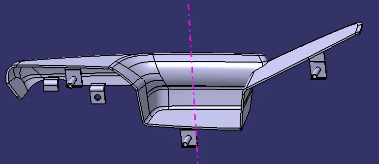
DRAFT ANALYSIS FOR ARMREST
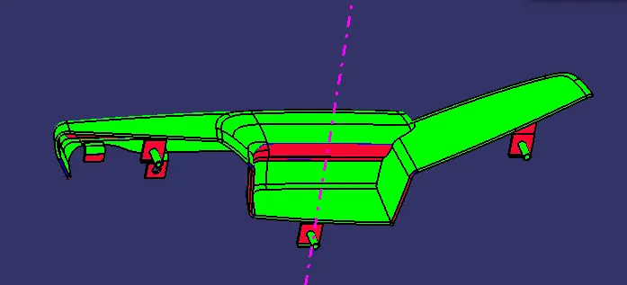
PERFORMED DRAFT ANALYSIS WITH 2.9 DEGREES
Some faces are not cleared with the tooling axis, because the given Class-A surface has some errors.
We have to modify the Class A surface.
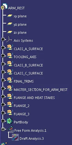
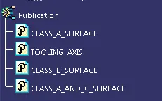
FEATURE TREE
PUSH CLIP
PUSH CLIP SKETCHING
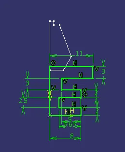
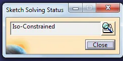
ISO CONSTRAINED
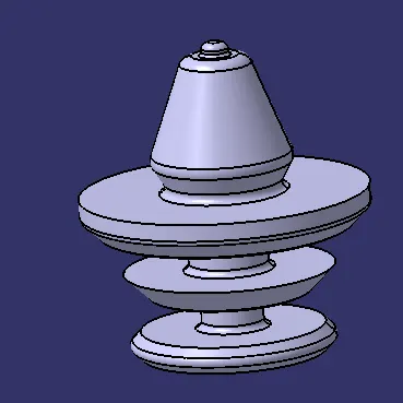
PUSH CLIP SOLID BODY
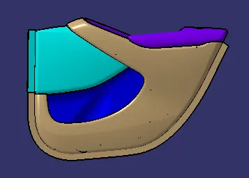
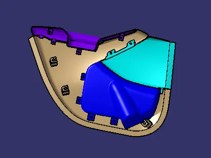
ASSEMBLY OF DOOR TRIM PANEL
FRONT SIDE
REAR SIDE
CONCLUSION
- Created Class A surface, Class B surface, and Class C surface.
- Created solid body.
- Created thickened part using master section for reference.
- Created the mounting features as per design guidelines in the industry and with master sections.
- Created Draft analysis & Tooling analysis.