Radar Mast & Final Assembly of Yacht
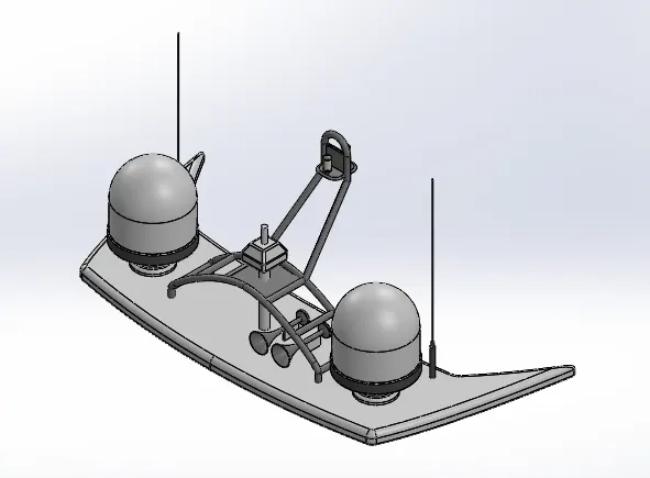
Radar Mast isometric view
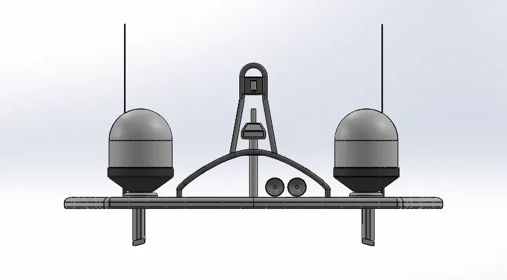
Radar Mast front view
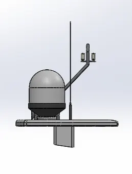
Radar Mast side view
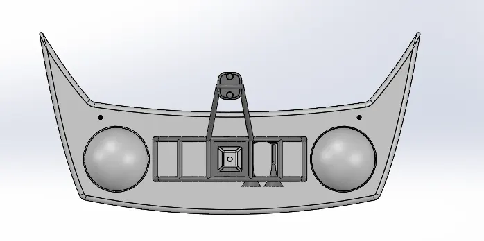
Radar Mast top view
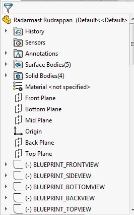
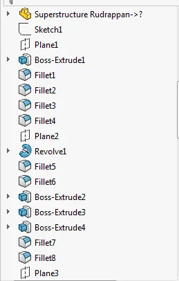
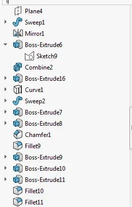
Radar Mast feature tree
Yacht assembly isometric view
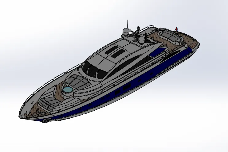
Yacht assembly front view
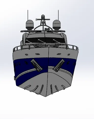
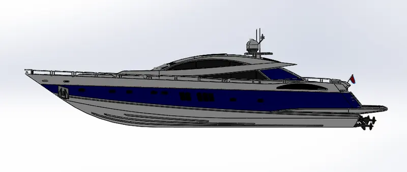
Yacht assembly side view
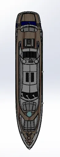
Yacht assembly top view
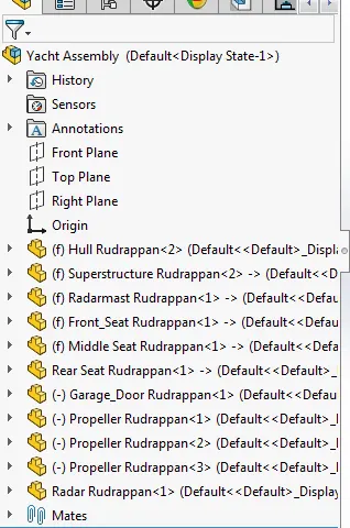
Yacht assembly feature tree
Modelling Yacht in Solidworks
Aim
The aim of this project is to design & model a Predator Yacht using Solidworks, by creating part drawings, converting them to 3D models, assembling the parts to create the model & finally giving it a realistic view by rendering the model using Photoview-360.
Introduction
A yacht is a watercraft used for pleasure or sports. The term originates from the Dutch word yacht (which means "hunt"), and originally referenced light, fast sailing vessels that the Dutch Republic navy used to pursue pirates and other transgressors around and into the shallow waters of the Low Countries.
Today's yachts are almost exclusively for leisure. A yacht is any sail or power vessel used for pleasure, cruising, or racing. The word often connotes luxury; however, luxury is not a quality necessary to meet the definition; nor is it always desirable. Many racing yachts are stripped-out vessels with a minimum of accommodations to lower weight.
Methodology
The different parts required to set up a Yacht such as the Hull, Superstructure, Propeller, Front Seat, Middle Seat, Rear Seat, Radar, Radar Mast & Garage Door were modelled to the required dimensions by part modeling.
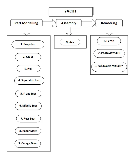
The different commands & features that were used to model the parts are as follows
- Creating a 2D sketch : A 2D sketch is a base to create a 3D model. It is usually created on the X-axis & Y-axis. This includes lines, circles, rectangles, splines, etc. Trim : The trim command is used to remove or erase the extra edges of intersecting lines on a 2D sketch.
- Offset : Add sketch entities by offsetting faces, edges, curves, or sketch entities to a specified distance.
- Boss Extrude : It extrudes a sketch or selected sketch contours in one or two directions to create a solid feature.
- Extruded Cut : Extrude cut is a feature that helps to remove materials from the 3D model. It is just opposite to extrude boss/base feature because it cuts a sketch profile while extruding. It can cut in both directions and mainly used for creating holes, channels, slots etc.
- Revolved Cut : Cuts a solid model by revolving a solid profile around an axis.
- Revolved Boss : Revolves a sketch or selected sketch contours around an axis to create a solid feature.
- Swept Boss : This feature sweeps a closed profile along an open or closed path to create a solid feature.
- Loft : The loft feature creates a shape by making transitions between multiple profiles and guides curves thus allowing to create complex geometry with a single tool.
- Dome : A dome is a rounded vault forming the outside face of a body or structure, typically with a circular base.
- Combine : This feature is used to combine two or more solid bodies together.
- Fillet : A fillet is used to connect two adjacent faces using a smooth tangent arc.
- Chamfer : The chamfer command is used to connect two adjacent faces using an inclined line.
- Surface Extrude : Using this feature, we can extrude the boundary edges of a face of a solid body or edges of a surface body in a customized direction. A planar surface body is used to extrude its boundary edges.
- Ruled Surface : This feature inserts a ruled surface from the selected edges.
- Extend Surface : Extends the edge, multiple edges or the face on a surface, based on end conditions & extension type.
- Surface Fill : Constructs a surface patch within a boundary defined by existing model edges, sketches or curves.
- Boundary Surface : Creates a boundary surface between profiles in two directions.
- Lofted Surface : Creates a lofted surface between two or more profiles.
- Offset Surface : Creates offset surfaces using one or more contiguous faces.
- Surface Trim : This feature is used to trim one or more intersecting surfaces by selecting a cutting edge as the trim tool.
- Swept Surface : Creates a surface feature by sweeping an open or closed profile along an open or closed path.
- Surface Knit : Combines two or more adjacent, non-intersecting surfaces together.
- Shell : This feature removes material from a solid body to create a thin-walled feature.
- Mirror : This allows to mirror features, faces & bodies along a face or a plane.
- Split Line : Projects a sketch to curved or planar faces, creating multiple separate faces.
- Linear Pattern : Patterns features, faces & bodies in one or two linear directions.
- Circular Pattern : Patterns features, faces & bodies around an axis.
- Projected Curve : This feature is used to project a sketched curve onto a face or sketch.
The overview of different parts is given below.
Propeller
- A propeller is a rotating fan like structure that is used to propel the yacht by using the power generated and transmitted by the main engine of the yacht. A yacht can be fitted with one, two, or three propellers depending upon the speed and manoeuvring requirements of the vessel. In this case, three propellers were used. Features like Revolve, Loft, Cut Extrude, Fillet & Circular Pattern were used to model the propeller.
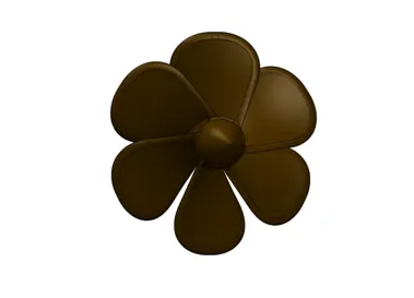
Fig1(a).Solidworks image of Propeller
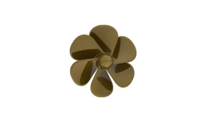
Fig1(b).Rendered image of Propeller
Radar
- The radar is a vital component for safety at sea and near the shore. It is used to detect other ships and land obstacles, to provide bearing and distance for collision avoidance and navigation at sea. They are electronic navigation instruments that use a rotating antenna to sweep a narrow beam of microwaves around the water surface surrounding the ship to the horizon, detecting targets by microwaves reflected from them, generating a picture of the ship's surroundings on a display screen. A Radar has a flat antenna that spins, emitting a signal, then listening back for that signal. The return signal bounces back at varying times based on what it may be bouncing off. Features such as Boss Extrude, Fillet, Cut Extrude, Sketch Pattern, Mirror, and Split line to insert the text were used to model this part.
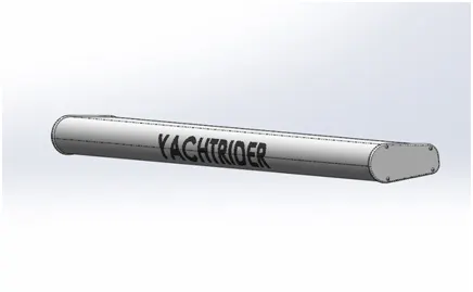
Fig2(a).Solidworks image of Radar
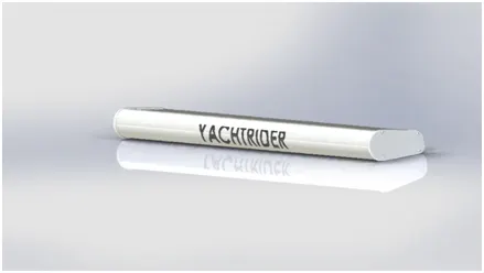 Fig2(b).Rendered image of Radar
Hull
- The hull is the main body of the yacht below the main outside deck. The hull consists of an outside covering (or skin) and an inside framework to which the skin is secured. The skin and framework are usually made of steel and secured by welding. The hull is the watertight enclosure of the yacht, which protects the cargo, machinery, and accommodation spaces of the yacht from the weather, flooding, and structural damage. Atop the deck may be a deckhouse and other superstructures, such as a funnel, derrick, or mast. The line where the hull meets the water surface is called the waterline. The hull of a ship is the most notable structural entity of a yacht. Both Solid Modelling & Surface Modelling tools were used to model the hull. Almost all the commands & features mentioned above in the commands & features section were predominantly used to model the part.
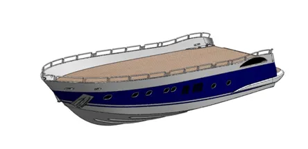
Fig3(a).Solidworks image of Hull
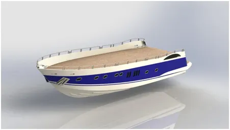
Fig3(b).Rendered image of Hull
Superstructure
- The Superstructure consists of the parts of the yacht, that project above the main deck of the hull. The size of a watercraft's superstructure can have many implications in the performance of ships and boats since these structures can alter their structural rigidity, their displacements, and stability. The Superstructure consists of complex curvatures. These complex structures were modelled predominantly using surface modelling using features such as Surface Loft, Surface Fill, Ruled Surface, Extrude Surface, Extend Surface, Surface Trim, Knit Surface, Offset Surface, Mirror, Fillet, Chamfer & some of the solid bodies like vipers & staircases were modelled using features such as Boss Extrude, Cut Extrude & Sweep.
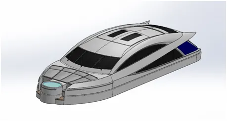
Fig4(a).Solidworks image of Superstructure
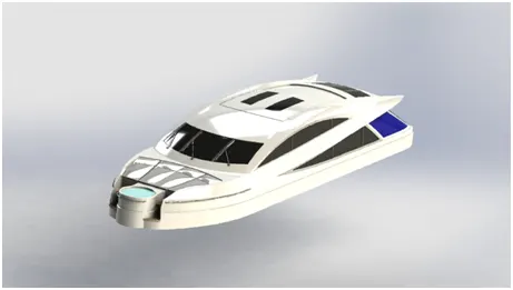
Fig4(b).Rendered image of Superstructure
Front Seat
- The front seat is a passenger seat. This is placed in front of the Superstructure. This part was modelled using features such as Surface Loft, Surface Sweep, Surface Extrude, Surface Fill, Surface Trim, Knit Surfaces, Boss Extrude, Revolve, Chamfer, Fillet, Dome & Mirror.
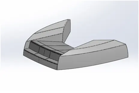
Fig5(a).Solidworks image of Front Seat
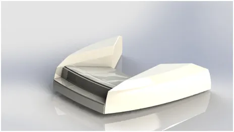
Fig5(b).Rendered image of Front Seat
Middle Seat
- The middle seat is also a passenger seat. This is placed just behind the Superstructure. This part was modelled completely using Solid Modelling. Features such as Boss Extrude, Cut Extrude, Chamfer, Fillet & Mirror were used.
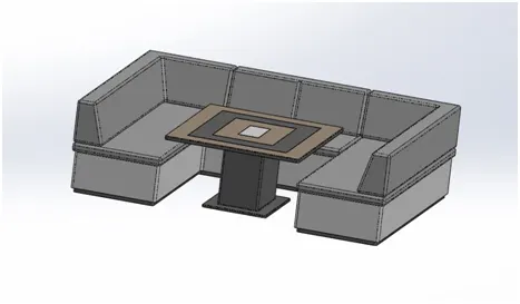
Fig6(a).Solidworks image of Middle Seat
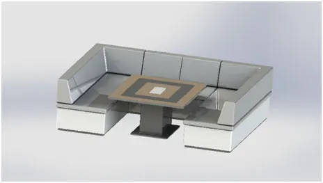
Fig6(b).Rendered image of Middle Seat
Rear Seat
- The middle seat is also a passenger seat. This is well behind the Superstructure, just in front of the back edge of the hull's deck surface. This part was modelled using features such as Surface Loft, Sweep, Ruled Surface, Surface Sweep, Surface Extrude, Surface Fill, Surface Trim, Knit Surfaces, Surface Offset, Boss Extrude, Revolve, Chamfer, Fillet, Dome & Mirror.
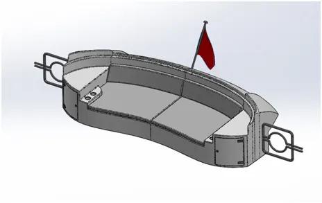
Fig7(a).Solidworks image of Rear Seat
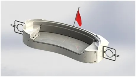
Fig7(b).Rendered image of Rear Seat
Radar Mast
- A radar mast is a tall spar or a hollow metal structure rising vertically from the top deck surface of the superstructure which supports the radar and its associated equipments such as the antennas and horns. This part was modelled using features such as Boss Extrude, Cut Extrude, Revolve, Sweep, Chamfer, Fillet, Dome & Mirror.
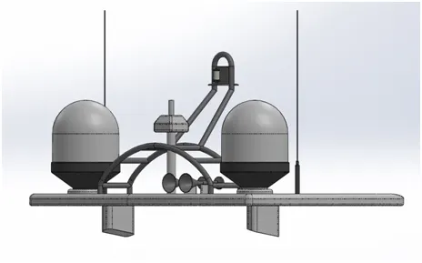
Fig8(a).Solidworks image of Radar Mast
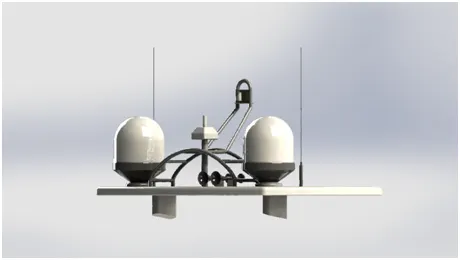
Fig8(b).Rendered image of Radar Mast
Garage Door
- A Garage Door is a large door that covers the opening through which a car or any vehicle enters and leaves the garage of the yacht. This part was modelled using features such as Cut Extrude, Shell, Fillet & Mirror.
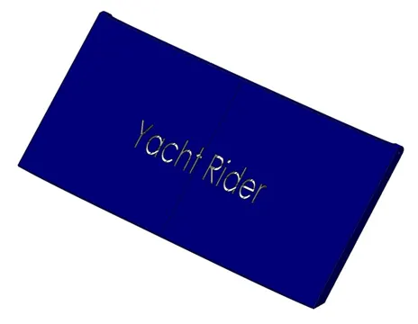
Fig9(a).Solidworks image of Garage Door
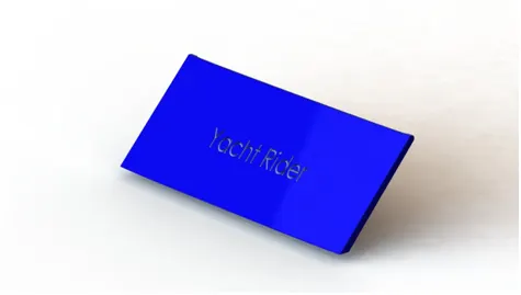
Fig9(b).Rendered image of Garage Door
Finally, all the parts were assembled in a Solidworks Assembly file by inserting each part, one after the other using suitable mate relations.
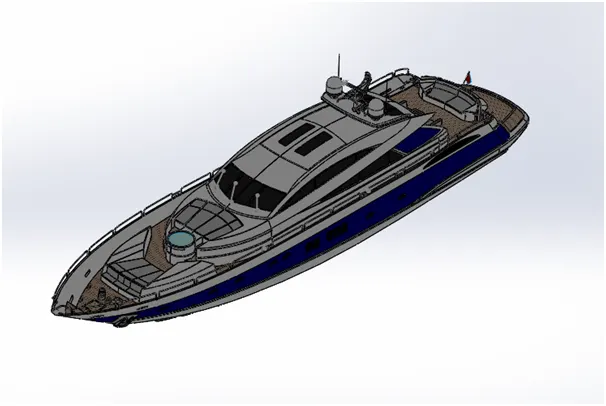
Fig10(a).Solidworks isometric view of Yacht
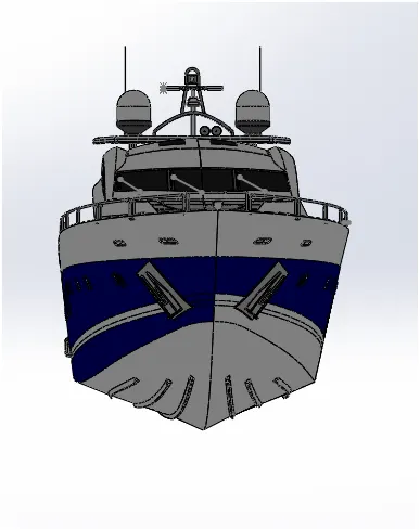
Fig10(b).Solidworks front view of Yacht
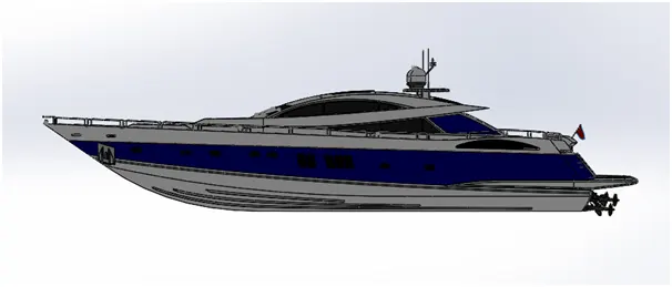
Fig10(c).Solidworks side view of Yacht
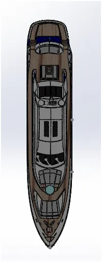
Fig10(d).Solidworks top view of Yacht
The different views & scenes of the rendered model of the yacht are as follows.
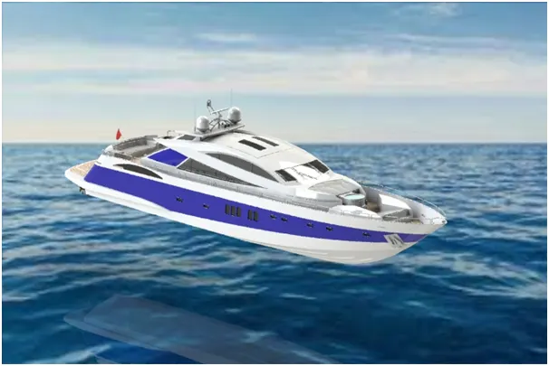
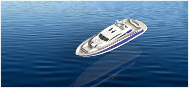
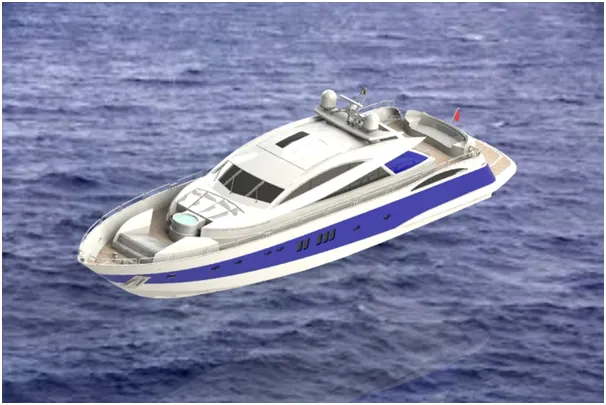
Fig10(e).Rendered images of Yacht
Result
- Thus, the different parts of the Yacht were assembled and rendered to give a realistic view using Solidworks & Photoview-360 respectively.