Week-11 : Discretization of 3D intake manifold using GEM-3D
The objective of this report is to explore the following listed topics:
- Identify the effects of changing the discretization length in a example of single cylinder DI Engine provided by GT-Suite on simulation time and error in the simulation results
- Understanding and documenting the process of using GEM 3D to create a one dimensional model from its three dimensional counterpart.
Section 1: Effects of discretization on the simulation
Case Setup
To explore the importance of the discretization length, we take a simple model of single cylinder DI Engine provided in the examples folder by GT-Suite. Before we dive into the results, we wiil provide a brief summary about the models and provide images.
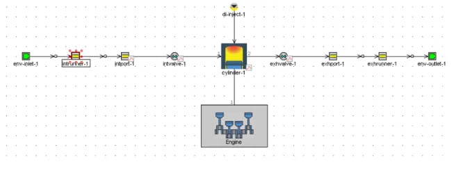
The model is CI, single-cylinder engine with two inlets and outlets which are connected to the intake and exhaust system respectively. Furthermore, the engine utilizies direct injection and is naturally aspirated.
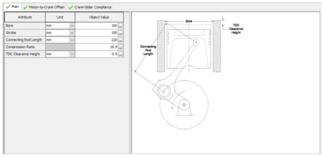
The above image provides details about the dimensions of the cylinder used for the simulation.
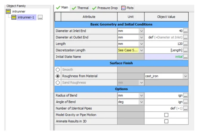
Now, to study the effects of the discretization, we create a parameter called "Length" and use it as a placeholder for the discretization length for the interrunner pipe.
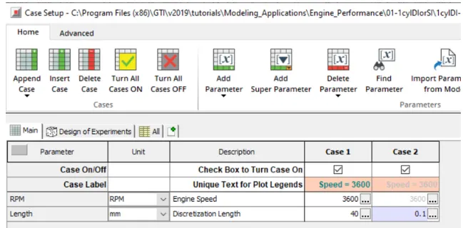
Next, we assign values to those placeholders in form of cases. In he first case, the value of the length parameter is set as 40 mm, while in the second case the length is set to 0.1mm.
Results and Plots:
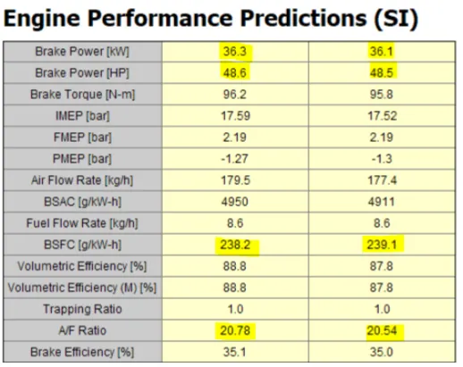
The comparison between the two cases on the basis of its engine performance. We see that the results have less than ~5% change in the values.
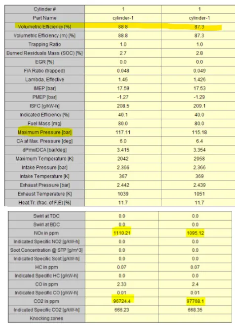
Similarly, a minor change, also within ~5% is observed for the values of the maximum pressure and NOx and CO2 emissions inside the engine cylinder.
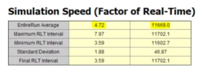
On the other hand, we see drastic difference for the speed of the simulation between the two cases. The Case 1 is almost 2500 quicker than Case 2 on average.
From this numerical experiments we can conclude the following:
1. Increasing the numerical simulation length does not always improve the simulation results.
2. The computational time required will incresase exponentially with smaller cell size
3. It is important to perform grid independence study to find a compromise between speed and accuracy.
Section 2: Intake manifold model from a STL file using GEM 3D
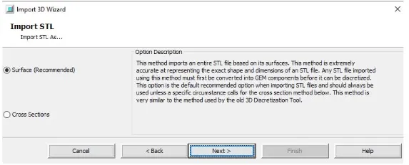
To begin, we must import the STL into the CAD environment. For this, we use the Import 3D application available with the GT-Suite. The previous step will initiate import 3D wizard.
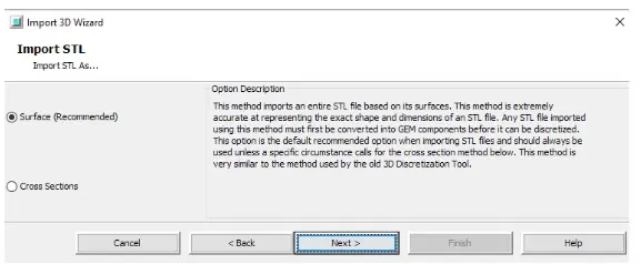
Since the STL files do not contain an unit information, it is important to select the correct unit while importing these files using the surface method.
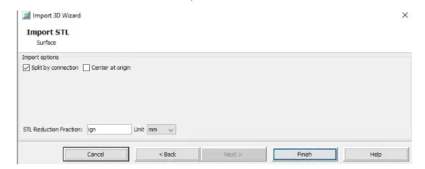
We set the units for our geometric model as mm. To complete this process, we choose the finish button.
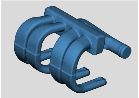
GEM3D will create a mesh shape component ('GEMMeshShape') from the imported shape and add it to the model, which should look like the image above (colors maybe different compared to the ones used for making the STL).
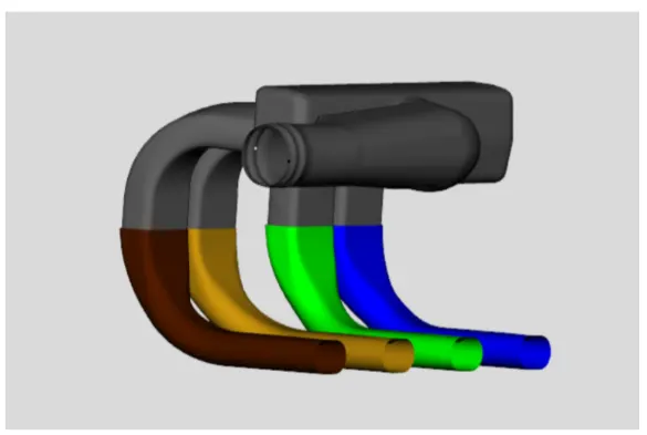
To allow the passage of flow through the intake manifold, we create delete the caps attached at the inlets and outlets of the intake manifold. For this, we use the tool 'separate the section by curve'. This will separate the geometry into parts based on changes in the surface of the object. This process will also separate the intake runners into two different sections near the area change at the top of the runners. Ensure the part is selected and choose Separate by Curves from the Shape Operations group in the Convert tab. After doing this procedure, we will observe that the final product is the image above.
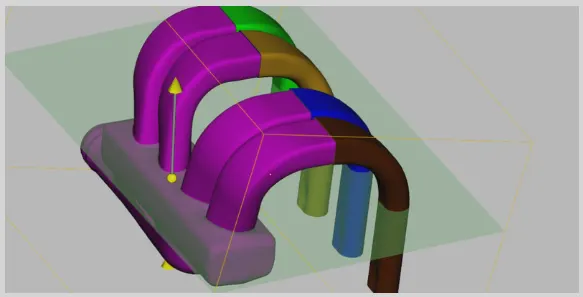
Now that the end caps have been removed, we can continue separating the shape into sections that can be represented by pipes and flowsplits. We will start by separating off the 4 runners from the manifold since the runners can be represented by pipes. To do this we will make use of the cutting plane operations available in the Cutting Planes group in the Convert tab. The cutting plane will be visualized as above.
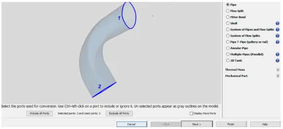
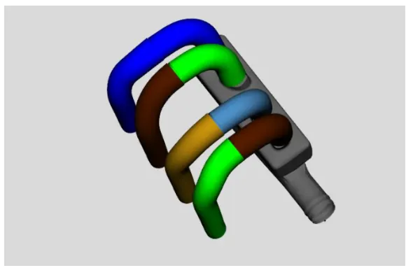
Now its time to convert all of the pipes into the flow components. We do this by right-clicking on the first section of the first runner (blue coloured bent section in the image above) and select Convert Shape to Component. This will open the convert mesh window, shown in the image below. Then we do it for all the pipes as seen below. This window appears once we right-click and select Convert Shape to Component. The port numbering suggests the flow of the air. We do it for all pipes and we convert all the pipes into 8 different components
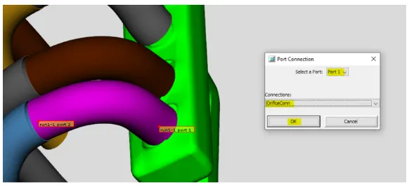
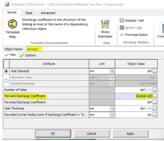
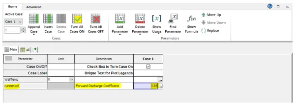
As the curved entry for the runners were lost while making the components, we need to connect them by makin a custom connection. The reason by this construction is to provide a more realistic modeling of the flow transition. To add a custom orifice to a flow component right-click on the first section of runner 1 (blue component in the image above, "run1-1") and choose Add Connection. We then select the forward discharge coefficient as a parameter in the orifice template and use it again for the remaining pipes as they have identical structure.
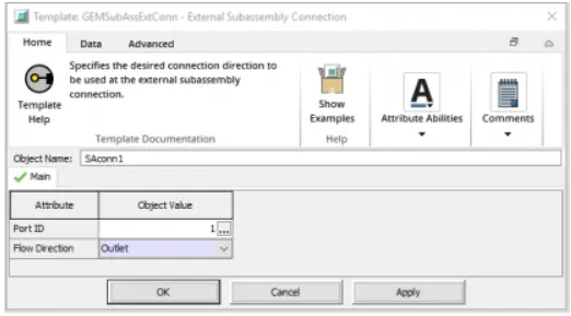
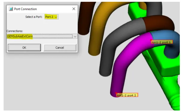
To enforce the direction of the flow throw the device, we enforce boundary conditions. For instance, at the port 2 of the runner pipes, we set the flow direction as Outlet in the ExtConnection Template. We repeat this step for rest of the pipes.
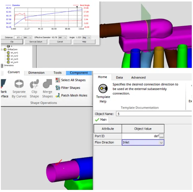
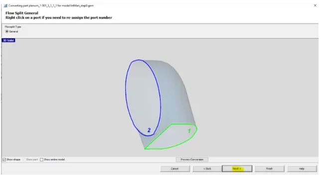
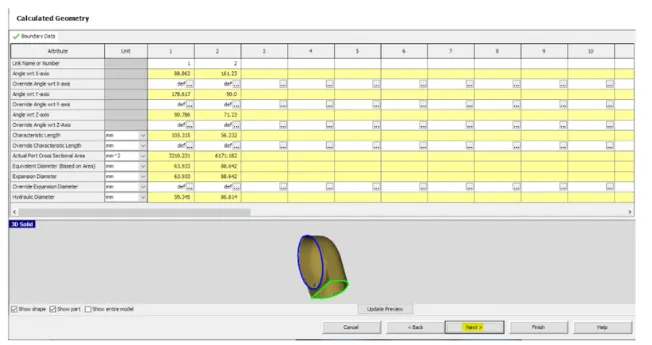
The inlet region of the runner has different cross-sections which makes it difficult to model it as a single part. Similar to what we did for the runner pipes, we split the pipes into several components of equal diameter. While doing this, we also chain our steps of correcting the direction of the flow by reordering the ports and setting the Inlet boundary condition. After this, the next step is to separate the manifold from the 90 degree entrance flow split. This must be done with the cutting plane operation, but will require use of some advanced features of that operation. The goal is simple, cut off the top flow split section without cutting through the manifold itself. This will be a multiple step process as we will need.
To do this Go to Convert tab > Cutting Planes group > Select 3 Points Cutting Plane. To place the plane, pick 3 points on the top of the manifold. Graphical operations are allowed so the model can be rotated, panned, and/or zoomed to make it easier (Do not to click on the shape during those operations or it will select one of the points). Then orient the plane is such a way that it does not cut the manifold or the flowsplit part. To orient it use the translate and rotate X, Y and Z slide bars. And adjust the Precision for translating and rotating the plane as required.
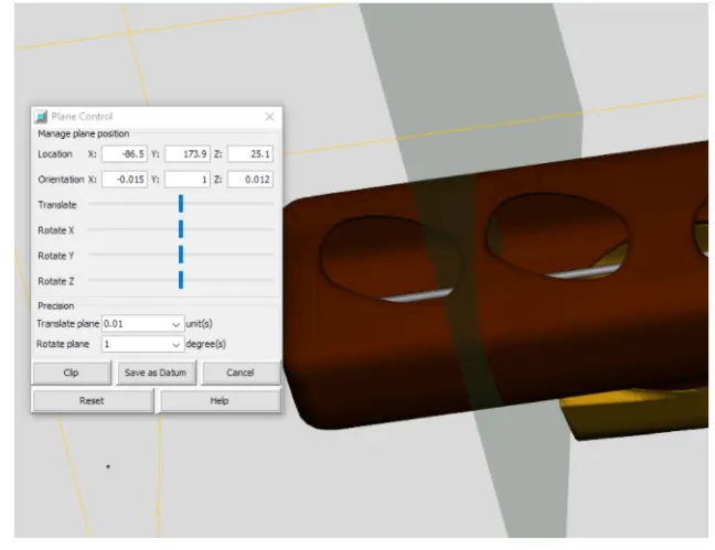
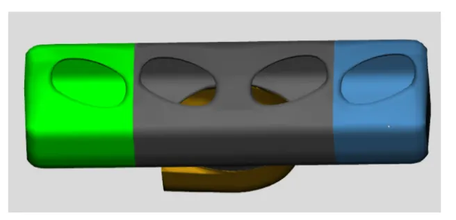
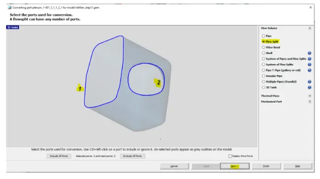
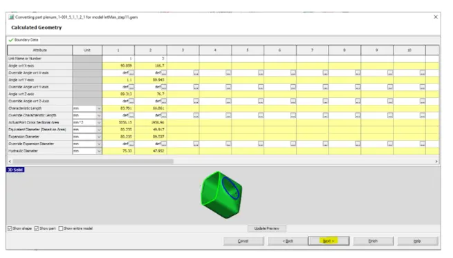
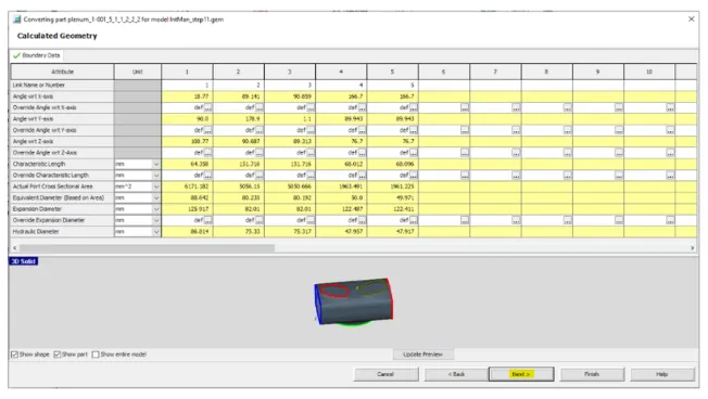
We need to make one more cut between the 3rd and 4th runners to finish dividing the manifold. Rather than picking 3 points again, we can restore the last used cutting plane. To do this, select Restore Cutting Plane from the Cutting Planes group in the Convert tab. This will place a cutting plane at the same location and orientation as the last one used and open the control window. Translate this cutting plane by dragging it with the mouse until it is between the 3rd and 4th runners, again being careful not to cut through the port openings. Once in place, select the mesh shape, then click the clip button. This will separate the end section from the center section, leaving 3 manifold sections like the image below.Now convert each section into a flow component. Select the end section near runner 1. right-click and select Convert Shape to Component. Select Flowsplit from the select the conversion geometry pane. Since flow is expected to enter from the side rectangular port, make sure that is assigned port number 1. Then click Next twice to convert and create the flowsplit.
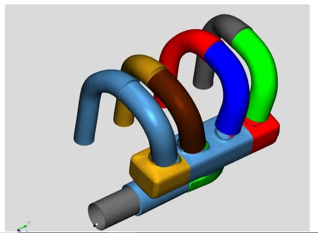
In the end, we will have the above shown components generated from the shape meshes.
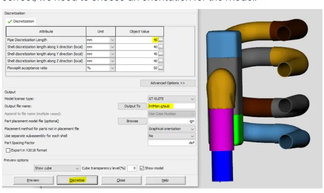
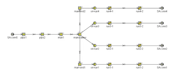
To make the final one-dimensional model, we discretize the the geometry using the standard settings. Finally, we get the resulting one-dimensional GT-Suite model.