Brief on Braking System of an Electric Vehicle
Week 11 Challenge: Braking
AIM:
(1) Calculate the energy required for braking for a defined driving cycle.
(2) Why electric motor can’t develop braking torque at high speed similar to starting? How electric and mechanical brakes are coordinated?
(3) Create a MATLAB program which plots contour of given motor speed, torque and efficiency values.
SOLUTIONS:
(1) Calculate the energy required for braking for a defined driving cycle.
Answer:-
The braking performance is one of the most important concerns in vehicle safety. In urban area driving, a significant amount of energy is consumed in braking. Electrification of vehicle makes it feasible to recover some of the energy lost in braking. A hybrid braking system was developed to ensure the efficient braking of vehicle and recovering the braking energy. The design and control objectives of such hybrid braking system is to ensure sufficient braking force to quickly reduce the vehicle speed, properly distributing the brake force to front and rear axle, and also to recover as much braking energy as possible. So understanding of braking energy of a driving cycle is important.
Governing Equation:
Braking Energy = `1/2*m*V^2` in `m/sec^2`
Where,
`m`- Mass of vehicle (kg)
`v` - Velocity of vehicle (m/sec)
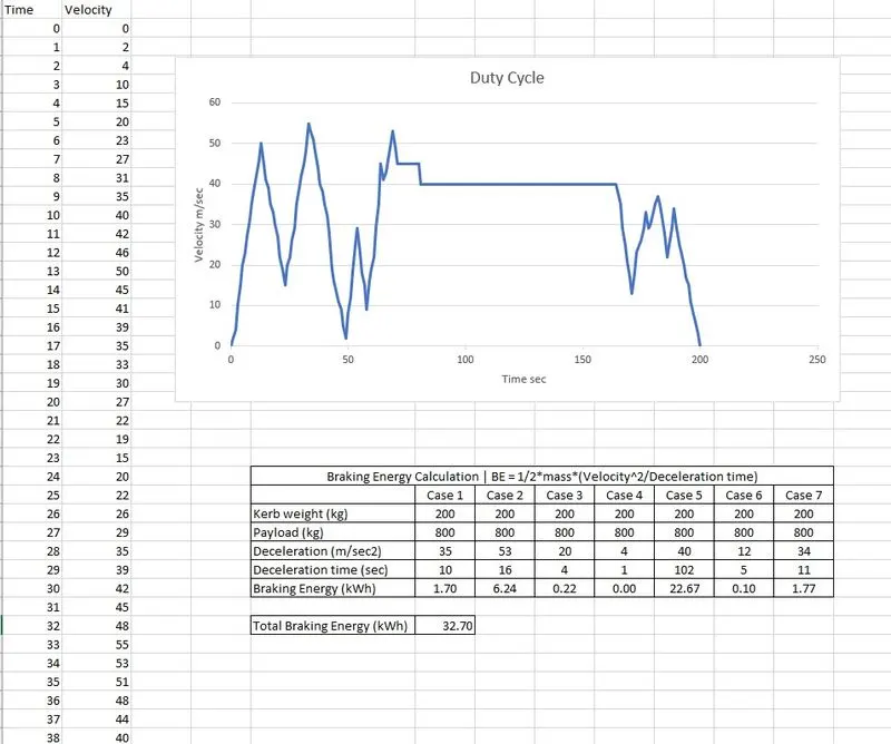
fig(i) The excel sheet calculator for braking energy
Comment:-
As per the defined duty the total deceleration time is around 2 mins 29 sec and the total braking required is 32.7 kWh.
----------------------------------------------------------------------------------------------------------------------------------------------------------------------------------------------
(2) Why electric motor can’t develop braking torque at high speed similar to starting? How electric and mechanical brakes are coordinated?
Answer:-
The figure represents forward motoring (positive torque and speed) and forward braking (negative torque and positive speed).
Sometimes after accelerating you can't reach the maximum torque. The reason is that no matter how much the current loop wants to increase current (proportional to torque) by increasing the PWM duty cycle of the power stage, the Vmotor is too close to Vbemf and therefore current can't increase more.
Whenever Friction torque + Additional loads = Motor Torque, the load remain in equilibrium (does not move, or moves under constant speed). Whenever Friction torque + Additional loads < Motor Torque, the load accelerates (Motor torque - Friction torque - Additional loads = Acceleration torque > 0). Al high speeds, the BEMF is so close to Vbus that the applicable Motor torque gets limited. Then, the bigger the Friction torque + Additional load is, the smaller the Acceleration torque becomes.
This can also occur if acceleration or speed is limited by some reason.
This situation does not occur at the beginning of an acceleration because most of the torque is used to increase the kinetical energy of the load (and motor). But when the speed is already high and no extra load is applied it is not possible to increase the torque.
And also we know that torque of the induction motor is in inverse proportional to the square of the rotor speed. So at higher speed the torque will be less. That’s why at high speed electric motor cannot produce braking torque similar to starting.
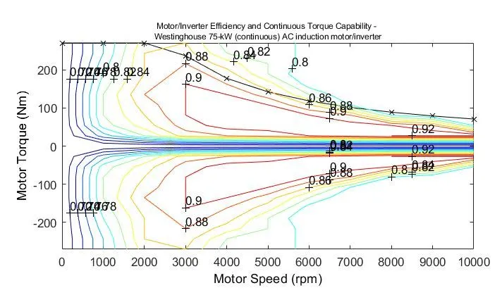
fig (ii) Speed-Torque contour for a motor
Coordination of Electric and Mechanical brake:
- Series - In case of Series we apply Mechanical brake and Regenerative electric brake one after another. We can apply only one brake strategy at a time either apply Regenerative or apply Mechanical brake. The Series Brake Control Strategy has further classification, that is based on whether we want comfort of driver or Brake behaviour compared to energy efficiency.
- Parallel - In case of Parallel we apply both brakes simultaneously. This Particular Parallel braking is going to happen both at a time.
Comparison:
| Electric Braking system | Mechanical Braking system |
| This systems are used for functional braking like controlling speed or bringing the load to standstill. | This systems are used for emergency stopping or for parking. |
| It is usually very smooth and comfortable. | It is usually rough and uncomfortable. |
| No wear results. | Causes wear in the braking systems and the energy os always lost as heat, noise and wear. |
| Cannot be used as a safety device. | Mostly used as a backup safey device. |
----------------------------------------------------------------------------------------------------------------------------------------------------------------------------------------------
(3) Create a MATLAB program which plots contour of given motor speed, torque and efficiency values.
Answer:-
The following the MATLAB script to plot the contour graph for the Motor speed, torque & efficiency values.
%%Program to plot efficiency contours for electric motors.

clear all
close all
clc

%Set up an array for range of the motor speed & torque
x = linspace (1,1000);    %Motor Speed | N.B. rad/sec
y = linspace (1,300);     %Torque | 0 to 40 N-m
The program starts with the clearing all the previous data, window or workspace values. To calculate the losses of the motor, we need the values of speed and torque. An array is defined to set a range for these values.
%Input constant values of Motor losses
kc = 0.2;                 %For Copper losses
ki = 0.008;               %For Iron losses
kw = 0.00001;             %For Windage losses
const = 20;               %For Constant motor losses
All the values of constant are defined which are needed to calculate the overall loss in the motor.
% Make a mesh
[X,Y] = meshgrid(x,y);
Output_power = (X.*Y);   %Power = Torque x Speed
B = (Y.^2)*kc;           %Copper losses
C = X.*ki;               %Iron losses
D = (X.^3)*kw;           %Windage losses

%Input power = Output power + Motor losses
Input_power = Output_power + B + C + D + const;
Z = Output_power./Input_power;   %Efficiency of the motor
Total loss of the motor is calculated with the efficiency. A dot matrix is used as the values of Speed & Torque are in an range (array).
%We now set the efficiencies for which a contour will we plotted
V = linspace(0.65,0.95,10);
[C,h]= contour (X,Y,Z,V);
xlabel ('Speed (rad/sec)')
ylabel ('Torque (N-m)')
clabel (C,h)
colorbar
hold on
title ('Motor Speed-Torque & Efficency contour lines')
box on
grid on

%%End of program
Now, plot the contour for the motor speed, torque & efficiency for the defined range of speed & torque.
Results:-
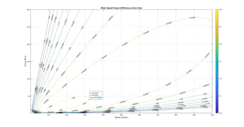
fig (iii) The contour graph of Speed Torque characteristics
Comment:-
From the output graph you could notice that only at particular speed and torque the efficiency is at maximum i.e. 90 %. where Speed x = 323.909 rad/sec @ 40 Nm Torque. As the Speed increases the efficiencies of the motor will be reduced.
Hence, to attain maximum efficiency of the motor has to constantly run at around 324 rad/sec speed @ 40 Nm.
----------------------------------------------------------------------------------------------------------------------------------------------------------------------------------------------
CONCLUSION:
(1) Created an Excel sheet calculator for calculating the energy required for braking for a defined driving cycle.
(2) Studied how electric motor can’t develop braking torque at high speed similar to starting and how electric and mechanical brakes are coordinated along with the comparison.
(3) Created a MATLAB program to plots contour of motor speed, torque and efficiency values and calculated to find the maximum efficiency of the motor which has to constantly run at around 324 rad/sec speed @ 40 Nm.
REFERENCE:
- https://doc.ingeniamc.com/wiki/motion-wiki/why-sometimes-i-can-t-reach-100-motor-torque-when-is-already-turning#:~:text=This%20situation%20does%20not%20occur,possible%20to%20increase%20the%20torque.
- https://www.researchgate.net/profile/Lutfi_Al-Sharif/publication/311855874_Overview_and_Comparison_of_Electrical_and_Mechanical_Braking_in_Drive_Systems/links/585d68d008ae8fce48fe5f89/Overview-and-Comparison-of-Electrical-and-Mechanical-Braking-in-Drive-Systems.pdf