Week-11 Challenge: Braking
EV Live batch 17
ANS 1:
Let us consider FTP75 drive cycle.
kerb mass=500 Kg
Payload =300 Kg
Total mass = m=800 Kg
Braking energy is equal to kinetic energy of vehicle during deceleration,
Therefore we can write
Braking energy = 0.5* m*(V2^2-V1^2)...V1 and V2 are the velocities of vehicle
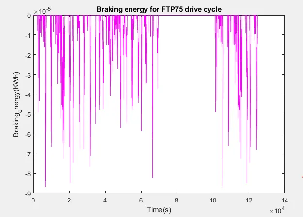
For the FTP75 drive cycle braking energy is calculated using Excel file
All instanteneous energy values are calculated, from all the values , only instateneous braking energy values and added and total braking energy is calculated.

Matlab code
clc
kerb_weight=500;
Payload=300;
m=kerb_weight+Payload;
t=drivecycle(:,1);
velocity=drivecycle(:,2); %velocity in m/s
instanteneous_braking_energy=zeros(1,length(drivecycle));
for i = 1:(length(drivecycle)-1)
if velocity(i+1)< velocity(i)
instanteneous_braking_energy(i)= (2.7778e-07*0.5)*(m)* ((velocity(i+1))^2 - (velocity(i))^2);
end
end
plot(instanteneous_braking_energy,'m');
xlabel('Time(s)')
ylabel('Braking_energy(KWh)');
title('Braking energy for FTP75 drive cycle');
fprintf('The total braking energy is %.3f Kwhr',sum(instanteneous_braking_energy));

ANS:2
Electric motor braking:
Electric motor cannot produce breaking torque at higher speed as similar to starting torque. This is because braking torque has to applied in opposite direction. We can do it by means of mechanical braking, electrically also we can do it.
At starting condition of the motor where the rotor speed is zero, as the back EMF is proportional to rotor speed, at starting we can assumed back emf zero. So the rated voltage given to the motor is fully available to draw the current.
At starting, the current is fully depend on resistance of the circuit. As there is no back emf opposition available to supply voltage the available voltage to draw current is rated applied voltage and hence large current flows through stator winding at starting condition. This produces high starting torque as compared to torque at high speeds.
At high speeds nearly as no load speed, as discussed above back emf is proportional to speed, it is nearly equal to supply voltage.so the current draw to produce the torque will be less and no such high torque can be produced as starting torque.
After base/rated speed as the speed increases the torque will abruptly goes down. if motor has to operate above base speed flux weakning is done wher torque is significantly reduces. We can't say that the 7 Nm of acceleration torque is equal to -7Nm of braking torque. Braking torque is always less. Due to all above discussed reasons, electric motor can't produce high braking torque at high speeds as similar to starting torque.
Coordination of electric and mechanical braking
The electric braking is regenerative braking and mechanical braking is friction braking.
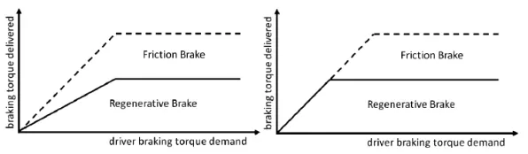
When there is braking demand from the driver pedal, considering the deceleration, speed of vehicle Brake intelligent system calculates the braking power required. If braking required is more than the maximum capacity of battery charging using regenerative braking, mechanical brkes has to be applied. In practical case the combination of two braking system is applied. This is done by braking control strategy. There are two tyes of braking control strategy as discussed below,
1. Series
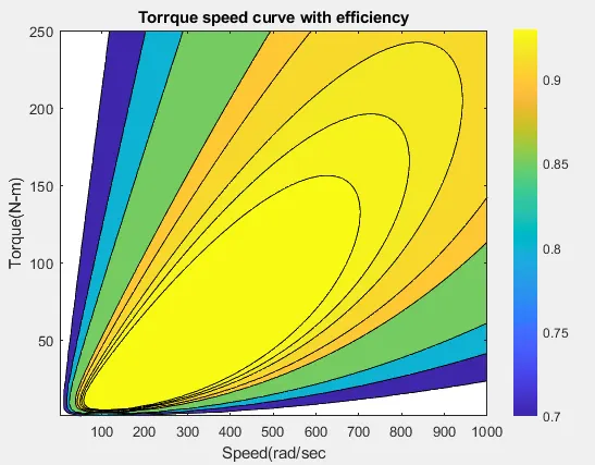
close all
clc
x=linspace(1,1000); % speed rad/sec
y=linspace(1,250); %torque N-m
ki=0.008; %Iron loss constant
kw=0.00001; %Windage loss constant
constantL=20; %For constant motor losses
[X,Y]=meshgrid(x,y); %Make a mesh
outputpower=(X.*Y);
B=(Y.^2)*kc; %Copper loss
C=X*ki; %iron loss
D=(X.^3)*kw; %windage loss
Inputpower=outputpower+B+C+D+constantL;
Z=outputpower./Inputpower; %efficiency
V=[0.70 0.80 0.85 0.90 0.91 0.92 0.925 0.93]; %contour plotted for this efficiencies
box off
grid off
contourf(X,Y,Z,V);
colorbar
xlabel('Speed(rad/sec');
ylabel('Torque(N-m)');
zlabel('Efficiency');
title('Torrque speed curve with efficiency')
hold on