Week-11 Challenge: Braking
1.
Answer:
Drive Cycle:
- The drive cycle is the data point of the speed of vehicle with respect to the time.
- It is the reference for any vehicle which determines its range and emission.
Braking Energy:
- Braking is the reducing the speed of any rotating machine.
- The enery release during the braking is due to the kinetic energy and friction.
- This total energy lost during braking is called braking energy and it is the sum of all energy during braking.
The braking energy is calculated by the below formla:
Braking Energy = `1/2*m*V^2`
Where,
m = Total mass of the vehicle
V = Velocity during deceleration
= Initial speed - Final speed
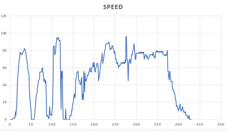
- The below graph shows the defined driving cycle.
- The formulas to calculate the braking energy of vehicle in excel file is given below:

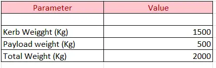
- The below table represents the total mass of the vehicle consider for calculating the braking energy.
- So the total energy calculated is given below in the table.
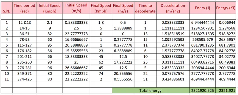
- So the energy required for braking during the entire drive cycle is 2321 KJ.
2.
Answer:
Why electric motor can’t develop braking torque at high speed similar to starting?
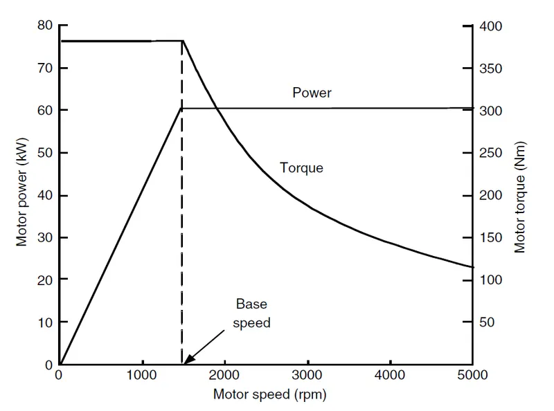
- Above figure shows the torque speed characteristics of the electric motor.
- The first region is the constant torque region in which speed is very low and the second region is the constant power region above base speed in which torque is very low.
- In constant torque region, applied voltage increases with the increase in speed and flux is constant.
- At the base speed or critical speed, motor voltage is equal to the source voltage.
- Above critical speed, motor voltage is kept constant and flux is weakened which drops with increase in the speed
- Therefore its torque also drops with the increase in the speed.
- Therefore electric motor can not develop torque at braking similar to the starting.
Mechanical brake:
- Mechanical brakes all act by generating frictional forces as two surfaces rub against each other. The stopping power or capacity of a brake depends largely on the surface area of frictional surfaces as well as on the actuation force applied.
- As the brake pedal is pressed cam rotates, which pushes the brake shoes outwards and hence brake lining provided on the outer surface of the shoes rub against rotating the drum and hence slow down or stops the vehicles because the drum is connected to the wheels.As the pedal is released, due to retracting spring force shoes return to its original position.
Electrical brake:
- The principle of working of this type of brake is to utilize the electromagnetic force on the brake shoes.It consists of an electromagnet, armature disc.
- An electromagnet is mounted on the backplate and armature disc is fed to the drum.
- This is simple in construction.
- For working, electric current for the battery is utilized to energize the electromagnet which actuates the cams that expands the shoes. Thus braking the wheel.
- The magnet in the backing plate has 2 conductor wires which tap directly into the trailer wiring.
- When electricity is on, it magnetizes the brake magnet.
- The magnet is attracted to the drum face.
- When it contacts this area, the friction causes it to rotate, which moves the actuating arm, and pushes the shoes out against the drum.
- Those shoes have a special brake pad material on them that resists the heat caused by that friction.
- When the shoes press against the inside of the drum, they prevent the hub, and consequently the wheel that's touching the ground from spinning.
Co-ordination between mechanical and electric brake:
- The brake distribution consists of two part which are electric brake called regenerative brake and mechanical brake
- The brake force distribution must be uniform in the vehicle.
- If the regenerative braking power requirement is more than the battery capacity or more than the regenerative capacity of machine then we must apply mechanical brake.
- In practice this two braking are combine which gives flexible braking in the vehicle which is called brake control strategies.
- There are two brake control strategies.
Series:
- The mechanical brake and regenerative brake are connected one after the another
- Only one brake strategy is applied at one tome either mechanical or regenerative.
Parallel:
- The mechanical and regenerative brake are connected in the parallel.
- Both brakes are applied simultaneously.
- The parallel braking is going to happen at one time.
Electric Driven Intelligence brake:
- It applies the combination of hydraulic or mechanical brake and regenerative brake.
- It is a parallel braking technique.
- The braking force is provided with the help of a ECU controlled motor and ball screw arrangement.
- This means that no direct load on the engine while applying brakes.
- This means that a motor operated the brake for providing the braking energy.
- A more controlled and uniform braking force is applied since its ECU controlled, this helps to recover braking losses when a regenerative braking system is used.
- At low speed regenerative braking is applied and at high speed combination of both is applied.
3.
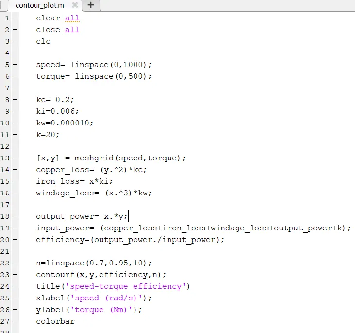
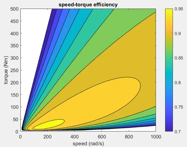
As shown in the above diagram, the maximum efficiency of 95 % is achieved during the speed range of 90 rad/sec to 313 rad/sec and torque range of 20 Nm and 45 Nm. The minimum efficiency is 70 %, which is achieved in the speed range of 242 rad/sec and 989 rad/sec and torque range of 500 Nm and 30 Nm.
It is seen from the graph that efficiency is maximum at the lowest speed and torque. As the spped and torque increases the efficiency is decreases.