Week-11 Challenge: Braking
Aim:- To calculate the Energy required for braking and Study on Different method of Braking.
Objective:-
- To defined driving cycle and calculate the energy required for braking.
- Why electric motor can’t develop braking torque at high speed similar to starting? How electric and mechanical brakes are coordinated.
- To make plot for contour of given motor speed, torque and efficiency values and attach a code in .m file.
Question:- 1] For defined driving cycle, calculate the energy required for braking.
Ans:-
Driving Cycle:-
- A Drive Cycle is a set of value, Generally Velocity(km/h) Vs Time(Sec).Which is represent how a vehicle travel through a path.
- A Driving cycle is an important tool that allows measurements between different vehicles and
regenerative braking systems.
There are two type of Driving Cycle:-
1] Model Driving cycle:- This model driving cycle comprises constant speed and does not represent a real driving pattern of a vehicle. These driving cycles will be used for specific applications such as an emission test.
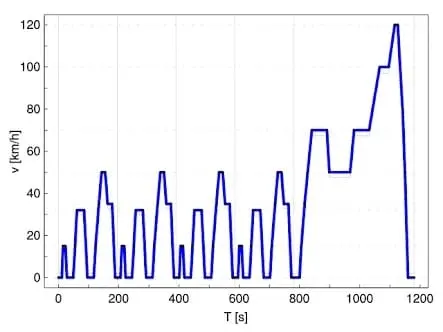
Fig:- New European Driving Cycle (NEDC) is an example of Model Driving Cycle.
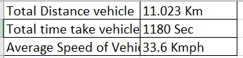
In the above graph,
2] Transient Driving Cycle:- This transient driving cycle represents an actual pattern of a vehicle which contains acceleration, deceleration, constant speed, etc. Federal Test Procedure (FTP 75) is an example of a Transient Driving Cycle.
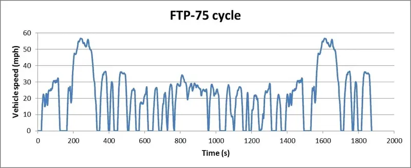
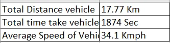
In the above graph,
Braking Energy:-
- The most common type of braking is a mechanical brake which inhibits motion through Friction brake pads.
- A mechanical brake apply a friction force to converted the Kinetic energy of the vehicle into thermal.
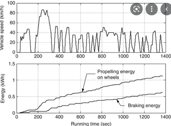
- In Regenerative braking system the Kinetic Energy is converted into the other forms of useful energy.Which can be stored for later use.
- The Kinetic Energy of a vehicle is given by,
`K.E=1/2mV^2` & (K.E) Energy required for Vehicle=`1/2m*(Vi-Vf)^2`
Where, m is the mass in (Kg)
V is the Speed of vehicle in Kmph
Vi is the initial speed of vehicle
Vf is the final speed of vehicle
We have consider Vehicle mass= 1000kg, Initial velocity of vehicle=25 Km/h and final velocity of vehicle=10 km/h. then we have calulate energy requred ,
We have used below formula for(K.E) energy requred for braking,
`E=1/2m(Vi-Vf)^2`
`=1/2*1000*(25-10)^2`
`=31.25kJ`
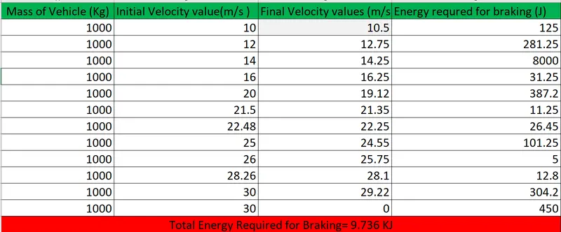
The Total Energy Required for Braking=9.736 KJ.
Question:-2] Why electric motor can’t develop braking torque at high speed similar to starting? How electric and mechanical brakes are coordinated?
Ans:-
The torque developed as induction motor varies when the motor accelerated from 0 to maximum operating speed.the motor beginning of an acceleration because most of the torque is used to increases in Kinetic energy of the load and motor.But when the speed is already high and no extra load is applied it is not possible to increase the torque.
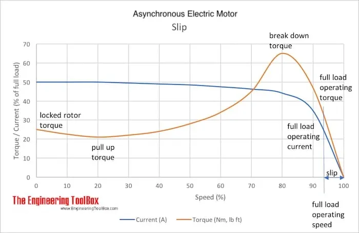
The starting torque is the torque an electrical motor developed when the starting at zero speed.In the full up torque is the maximum torqur developed by an electric motor.when it runs from zero to full load speed. when the a motor starte and higher to accelerate the torque in general will decreases untile it reach a low point.In the break down torque is the highest torque available before the torque decreases when the motor continues to accelerating to working condition.In the Braking Torque is the torque required to produce the rated power of an electrical motor at full load speed.
How electric and mechanical brakes are coordinated:-
There are to type of Brake Control strategies:-
1] Series Brake Control strategie:- In this strategies we have apply mechanical brake one after Electric brake.
2] Parallel Brake Control strategie:- In this strategies we have apply Mechanical brake and Electrical brake Both at a time.
Braking is used to stop / control the motors for different desired application.It reduces the speed of any rotating parts.
There are two types of braking used in the Electric drive namely:-
1] Mechanical Braking.
2] Electrical Braking.
1] Mechanical Braking:-
In this braking,The stored energy is dissipated as heat by a brake shoes or brake lining which rubs against a brakee drum. When you step on your petrol or diesel car’s brake pedal, hydraulic fluid pushes brake pads against brake discs on each wheel (or drums on older and cheaper models). The resulting friction works to slow the car down, generating heat and wearing away at the material on the pads and discs in the process.
Types of Mechanical Brake:-
- Shoe Brake- This brake Used in Electric cranes, older generation trains.
- Band brake- This brake Used in the braking system of certain bicycles.
- Band and block brake- This brake are widely used in trains
- Internally expanding shoes brake- This bake Used where low braking force is required in motorbikes.
2] Electrical Braking:-
In this braking methode, The stored energy of rotating parts is converted into electrical energy and dissipated by the resistance in the form of heat to the supply.This braking depend on the Direction of motor torque and Working flux of motor.
The three types of Electric Braking:-
1] Regenerative Braking
2] Plugging Braking
3] Dynamic Braking
1] Regenerative braking:- In this braking when Motor Speed (Ns) > Synchronous motor speed. First we have normal condition running motor the Torque and Flux rotating in same direction also current flowing same direction. Second we have change Direction of Current Ia and Toeque T Reverse. The braking is observed in second condition. This is used with Variable Frequency Source at sub synchronous speed.
In this braking is a way of taking the wasted energy from the process of slowing down a car and using it to recharge the car’s batteries. On a normal car, braking simply wastes energy - but with regenerative braking, some of the energy is able to be reused. In this braking are modern car, On petrol and diesel models, it’s used to charge the battery that runs various ancillary systems in the car, meaning less work for the engine and less fuel burned. In these cars, the system is virtually imperceptible to the driver but in hybrid and pure electric cars regenerative braking takes a more active and obvious role. In these models, brake regeneration can help charge the larger batteries that directly drive the car.
2] Plugging Braking:-
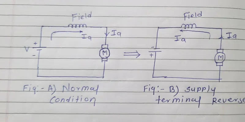
We can see in fig-A. the we have give normal supply and current passing through field winding CW dirction. We can see in fig-B We have change supply ternimal Voltage(Reverse Direction. the current flowing through field winding anti-Clock Wise diection. the torqur produces in motor also reversed menas Tm reverses the speed of motor reduction and thus the braking operation performed.
3] Dynamic Braking:-
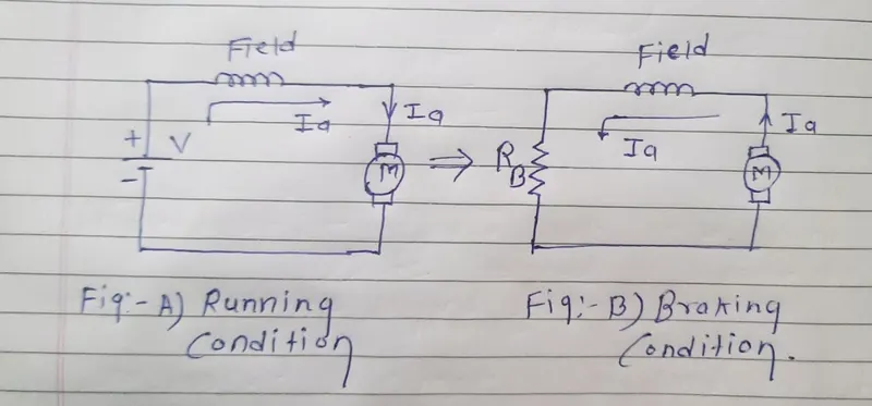
`Ia=(V-Eb)/(Ra)` and Become, `Ia=(-Eb)/(Ra+Rb)` therefore, Ia reverse and Tm also reverse then the speed reducing.
We can see in fig:-A We have give supply voltage. The current(Ia) is passing through field winding and motor are running condition.We can see in fig:-B, At running condition of motor it is disconnected from supply and connected across Resistor Rb.We have neglecting voltage supply and there we have placed Resistor(RB).then the current flowing throuth Anti-clock Wise direction. The Ia reversed and also Torque direction reverse then speed of motor reducing thus the brake is performing.
Question:-3] Make a MATLAB program which plots contour of given motor speed, torque and efficiency values. Attach the code as a .m file attach a screenshot of all the plots.
Ans:-
Coding for plots contour of given Speed (Rpm), Torque (N-m) and Efficiency values (%):-
% Matlab coding for ploting given Motor Speed, Torque and Efficincy value

clc
clear all
close all

% Velocity Arrey
V = linspace(1,1000);   % Velocity in rad/sec
% Torque Arrey
T = linspace(1,300);    % Torque in N-m

% Copper Losses Coefficient (Kc)
Kc = 0.25;
% Iron Losses Coefficient (Ki)
Ki = 0.008;
% Windage Losses Coefficient (Kw)
Kw = 0.000015;
% Motor Constant Losses (K)
K = 20;

% Calculation for Losses
Copper_Losses = (T.^2)*Kc;
Iron_Losses = (V.*Ki);
Windage_Losses = (V.^3)*Kw;

% Meshgrid
[V,T]=meshgrid(V,T);

% Calculation for Efficiency
Output_Power = V.*T  % Output Power = Velocity* Torque
Input_Power = Copper_Losses+Iron_Losses+Windage_Losses+Output_Power+K;
Efficiency = Output_Power./Input_Power;

% Efficiency Curve
n = linspace(0.7,0.93,10);

% Plotting Graph
contourf(V,T,Efficiency,n);
xlabel('SPPED (Rpm)')
ylabel('Torque (N-m)')
title('Torque Speed Curve of Induction Motor With Efficiency value')
colorbar
Output Plotting Results:-
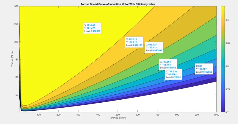
Above graph shown Speed Of Motor (Rpm) Vs Torque (N-m) and Efficiency value in %. The dark blue color indicated efficiency 70% and the light blue color the efficiency value 75% to 85% and Yellow color Indicated efficiency valve above 96%