Week 11 Challenge
1.Introduction :-
Effects due to temprature on bridge ,here we calculate the effect due to temprature difference on bridge.
According to IS 875 Part V, expansion and contraction due to change in temp. of materials of a structure shall be considerd in design .
2.Aim:-
Here the main purpose of calculate the temprature effect on bridge is to calculate the deflection and other load ,so we can design structure without any defect due to temperature effect .
3.Procedure :-
Here step by step we calculate the effect due to temprature differance .
As We find out the given Data as
1.Grade of concrete =M-40
2.Location =Delhi
for temperature differerance as per IRC 06
Max= 48.4
Min =-2.2
3.Span Of Bridge =9m
4.Width of Slab =7m
5.Dia of Pier =2.5m
6.Thickness of slab =0.550m
7.width of Cap =6m
8.Depth of cap =1.1m
9.Box Girder opening =1.5X1.5 m2
10.Thickness of web =300mm
Now , from given data we calculate the temperature load .
Stressing due to concrete=AlfaXDeltatXE
Here ,
Alfa= Coefficient of termal expansion
=11.7X10^-6 C
Delta T=Effective temp. difference
=(48.4-(-2.2))
=(50.6)/2+10
=35.3 C
E= Modulus of elasticity of concrete
=5000(fck)^0.5
=5000(40)^0.5
=31622.77n/mm2
=31.622kn/mm2
So,
Stress due to temp differance ,
= 11.7*10^-6*35.3*31.622*10^3
=13.060kn/m2
But as per IRC -06
Max Permissible stress
=2/3*Rupture of concrete
=2/3*0.7*(Fck)^0.5
=2.95Kn/M2
=3 kn/m2
So, Stress in bridge shall not excced 3kn/m2.
Now,
we create the model with help of staad pro and apply the load and get the results as given below steps ,
1.Open the Staad pro and create a new file for new model
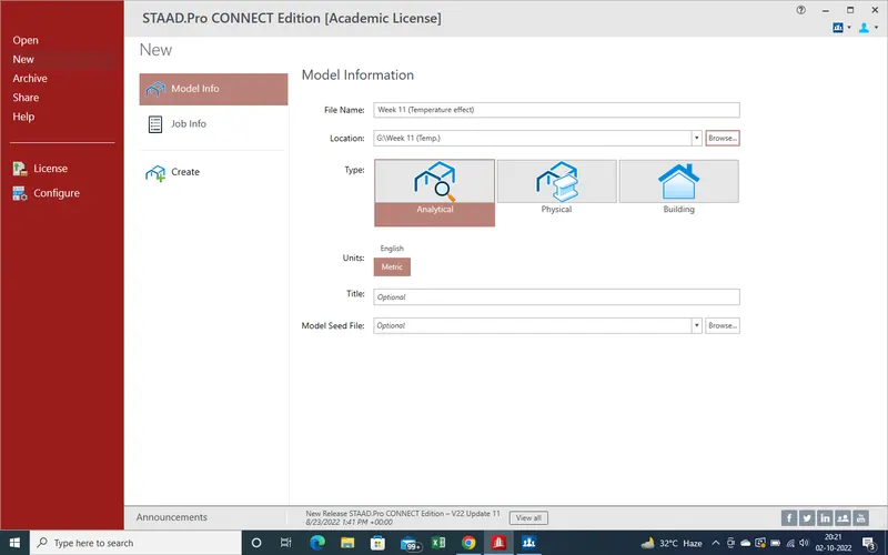
2.Now As we select "Create " an new window open which is main window .
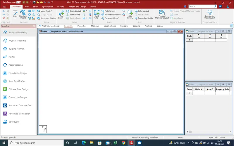
3. Start model with 0,0,0 orign as showing a node will appear on main screen and value showing side bar
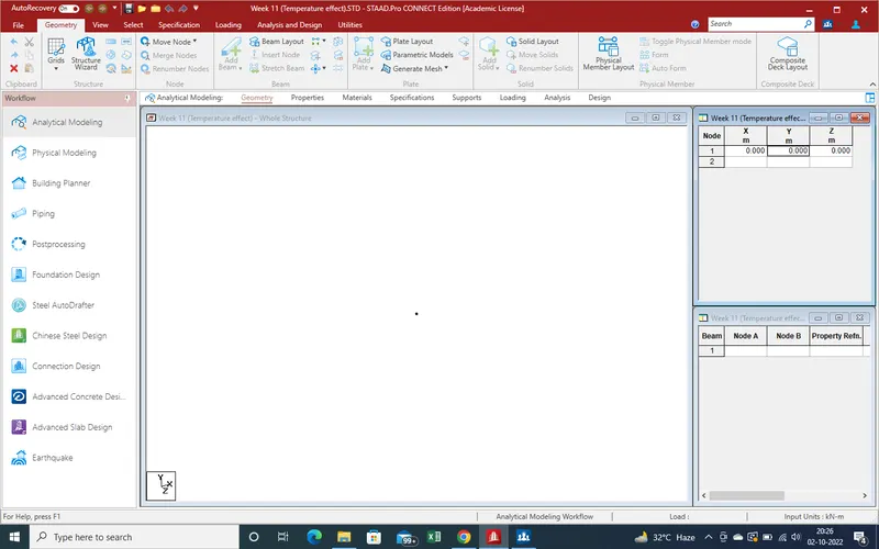
4. As per given Model as pier shaft height is 10 m so provide second point as 10m for y-Direction .
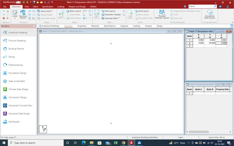
5.With the help of "Add beam " Command create the beam between both nodes as showing .
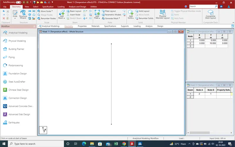
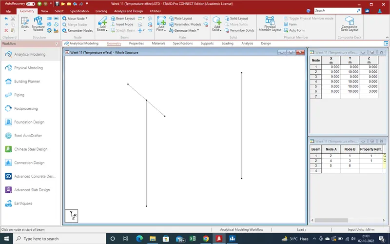
6. As Given data ,Span of Bridge is 9m so need same properties and same data pier at another end ,so with help of translation repeat command create another pier .
Select beam for translation repeat command .
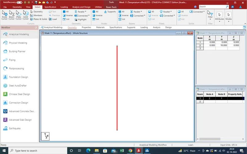
Select the translation repeat commad ,First select the direction as here X-Direction select for next pier as
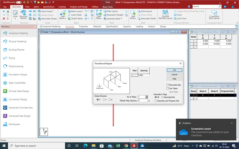
As spacing is 9m between both pier and no of steps are only 1 so place the value as showing .
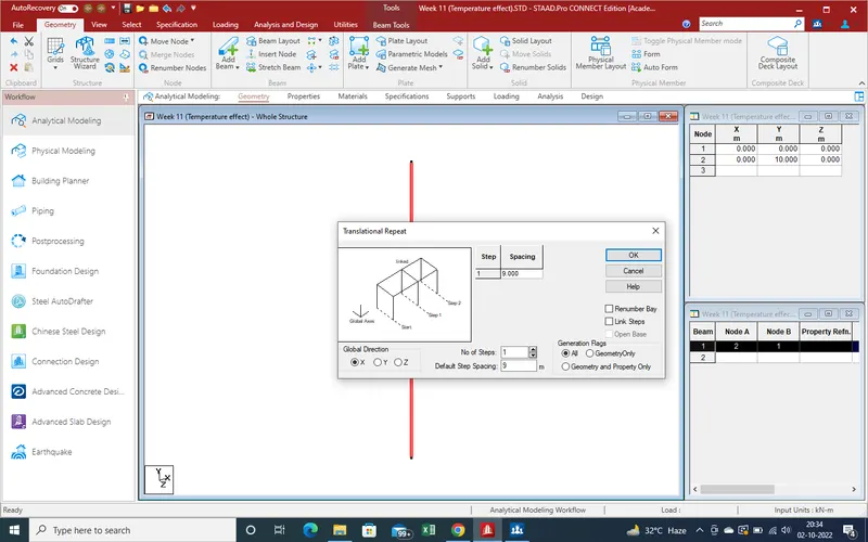
And get the results as showing .
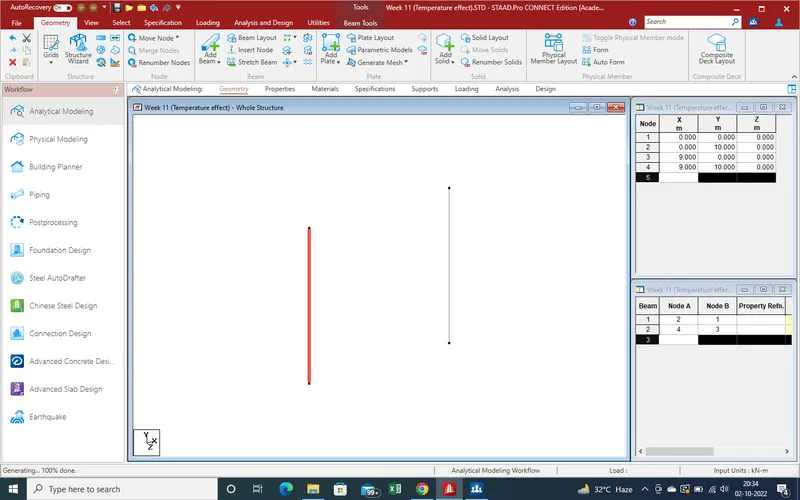
7.Select the properties for pier as given data pier is circular so create the properties as per given data and assign as given steps as .
In specification section Select the "Prismatic Beam " section .
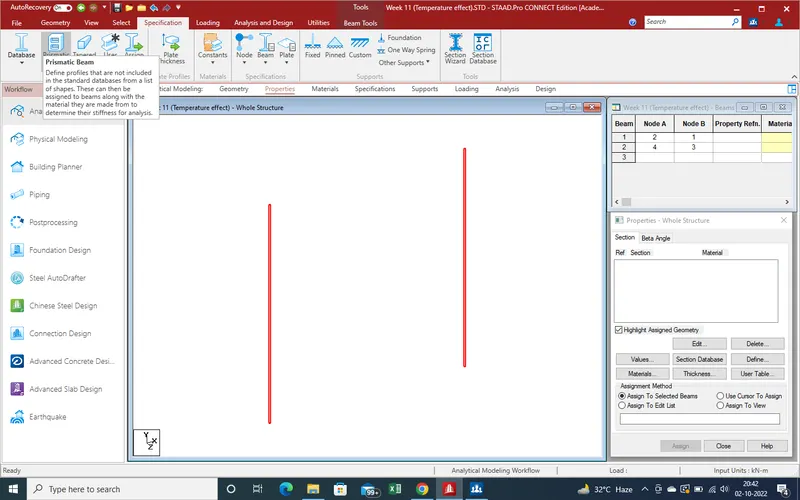
As select the prismatic a new window open as showing ,here need to select the type of shape .
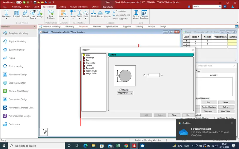
As here given data , Pier has 2.5 m dia circular pier so select the circuler shape and put the value of Dia as 2.5m.
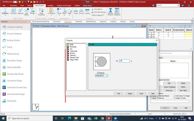
As we click on add ,"at side bar properties " created " for asign .
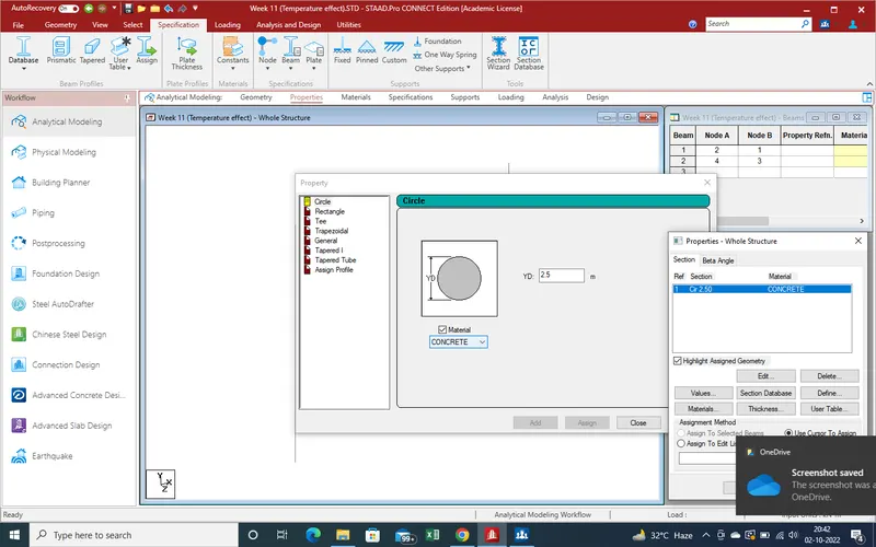
Select the pier on which we need to assign
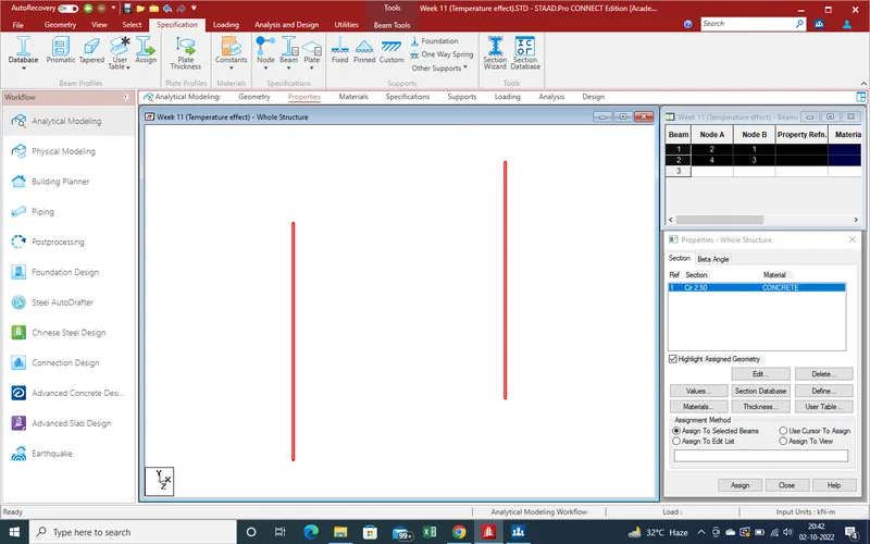
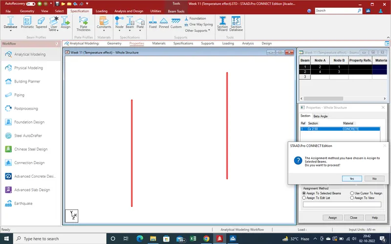
As we select the assign it again confirm that is it ok .
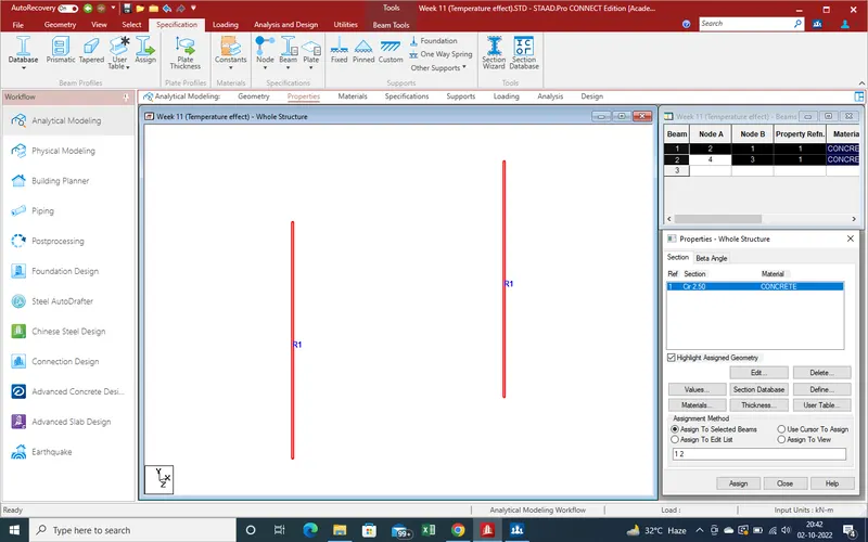
After confirmation properties has assign as showing .
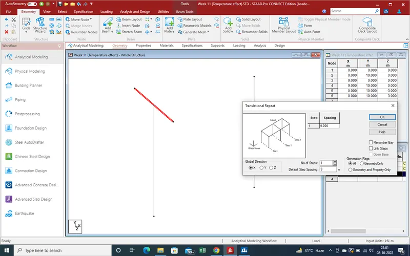
8.Now need create Pier cap as pier cap also an beam so need two node as pier reqired . now create node with help of traslation repeat command and create the beam both pier .
Go to Select section for selection of node cursor .
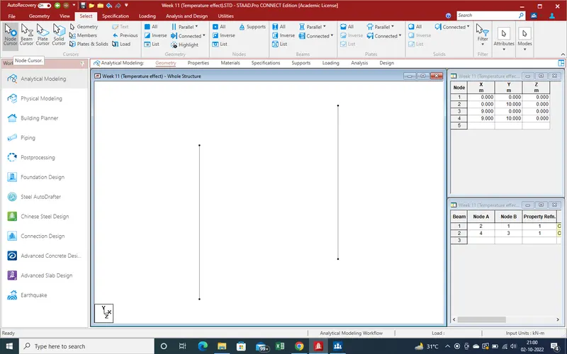
As pier is mid if pier cap and pier cap width is 6m ,so select the z in Negetive direction with 3m distance .
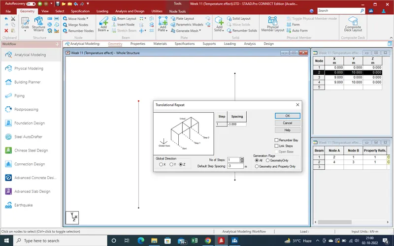
Same as for forward side and create node for beam as pier cap .
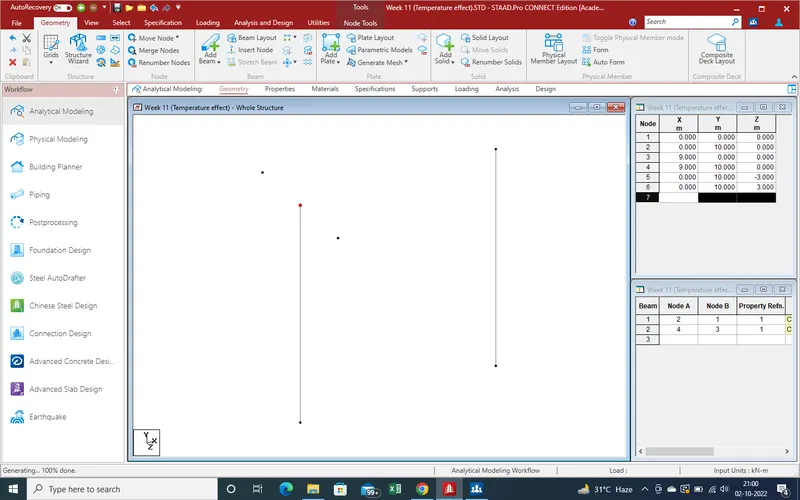
Now Create the Beam With help of "Add Beam " .
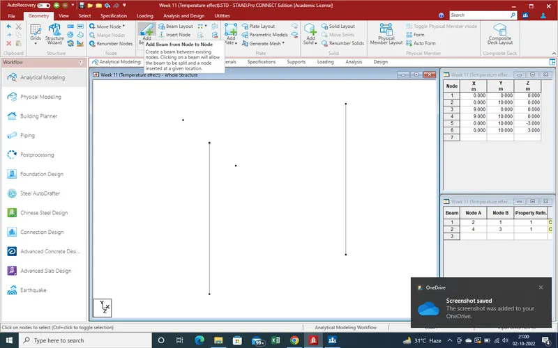
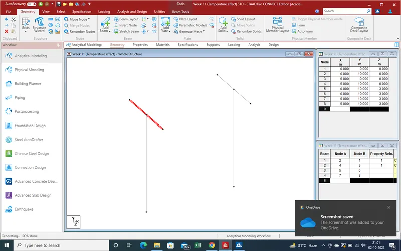
And Get the results as
Now another side with help of translation repeat command create pier cap
And get the results as
Now Apply properties ,
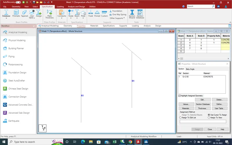
When select the "Prismatic" section click a new window open as showing .Here our cap is rectangle so selelct the rectangle section and put the widthand depth value of cap as showing .
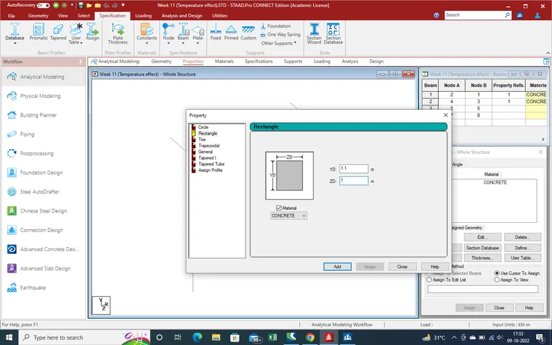
After add the properties , select the cap for apply the properties as showing given pic below .
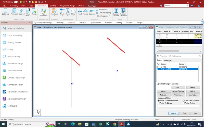
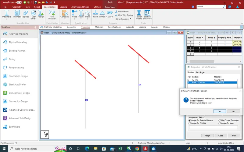
When we assign the properties ,it will confirm again for check that we are right .
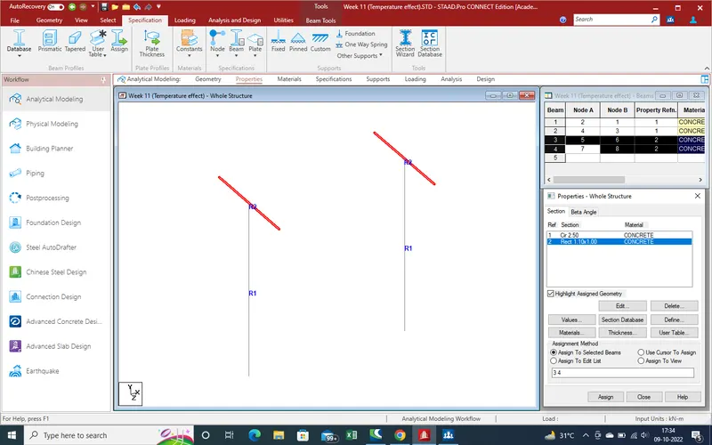
Properties has been applyed to cap .
9.Now need create the node for box girder . As we calculate manual ,from centre outer point shall be 2.1m.
Now we create the node for box girder with the help of translation repeat command and create node .
Select the node for translation repeat command
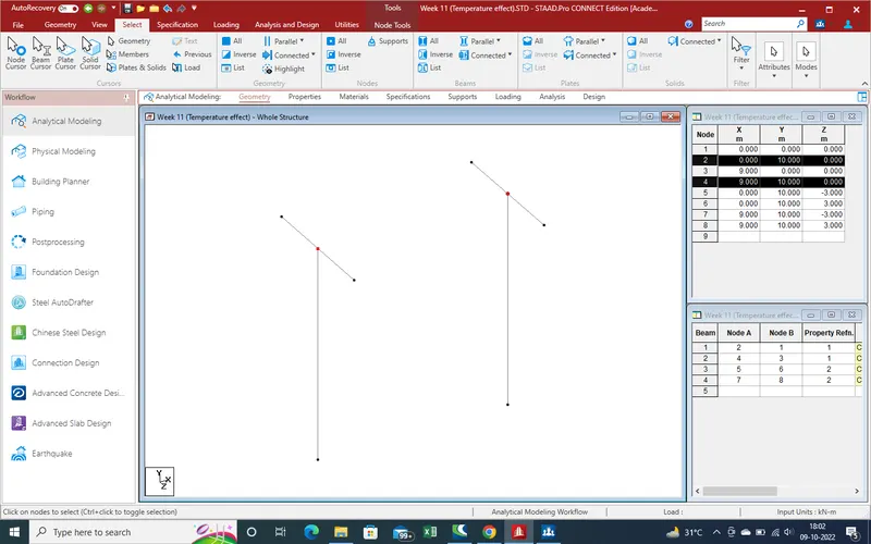
Select the distance as 2.1m and value shall be negetive for backward side in Z-direction .
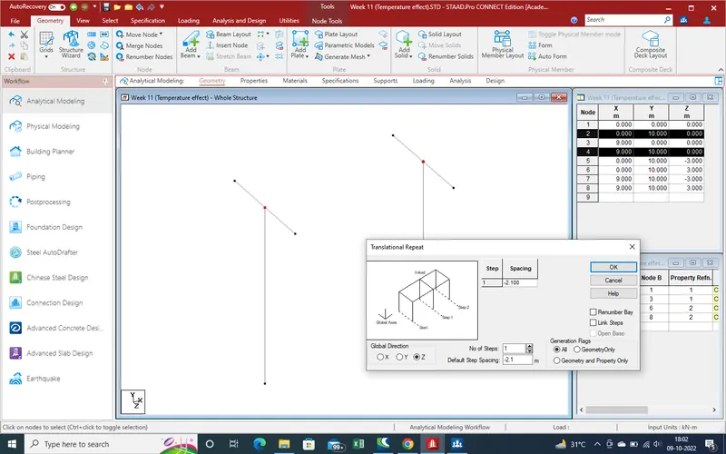
Same for forward direction shall be take positive in Z-direction and apply .
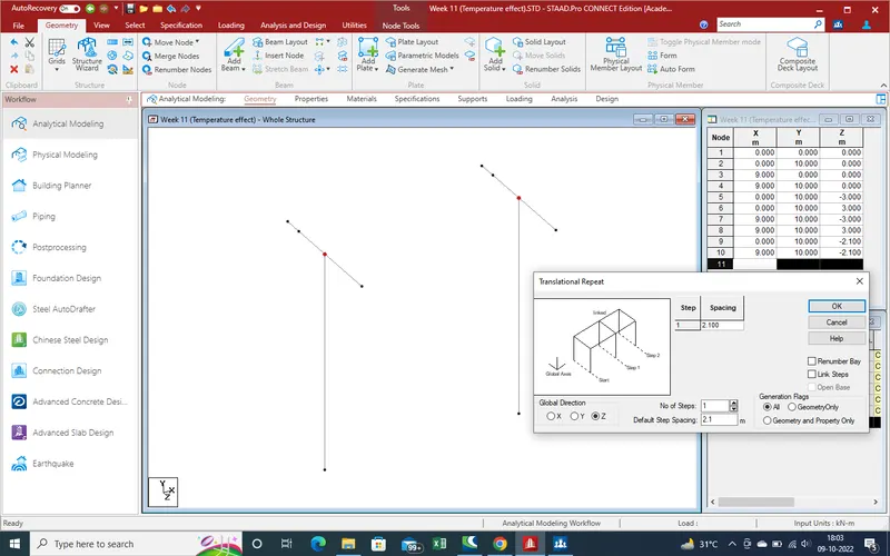
Get the node for create the beam as for box girder .
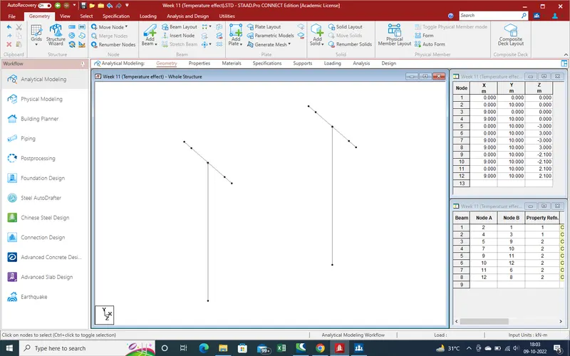
10.Create the beam with the help of "Add Beam "
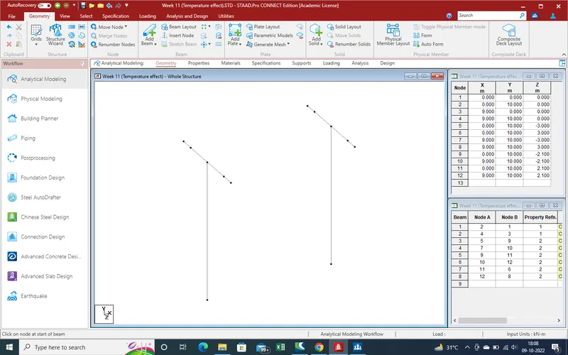
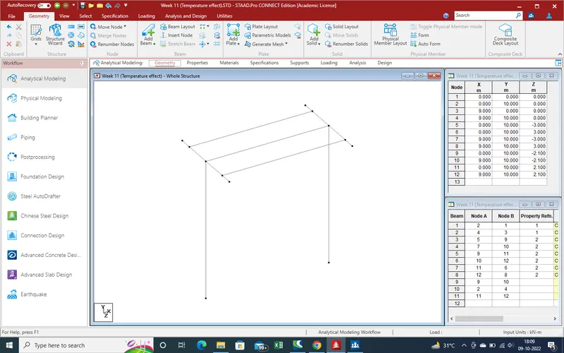
11. As per given data we apply the properties for box girder .
As we select the properties a new window will open and option for select the section of beam .
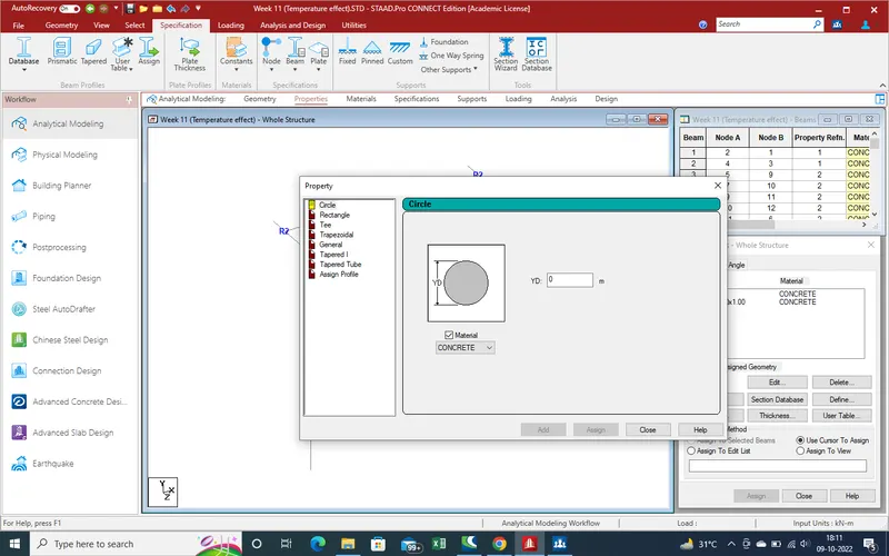
As box girder beam are as tube type of squre shape ,so select the tube section as showing
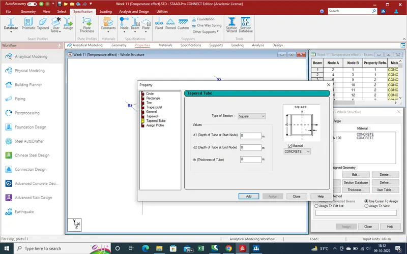
Here we need the put the values for thickness of wall and inner height which are such as 1.5m height and thickness of wall /web are 0.300m
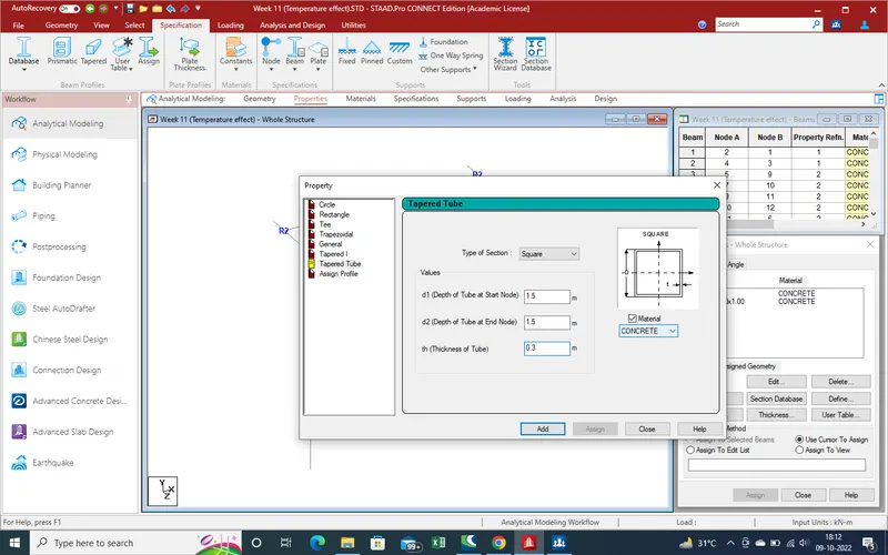
Select the add and close the window and get the properties in side bar . Now select the beam where we need apply as showing .
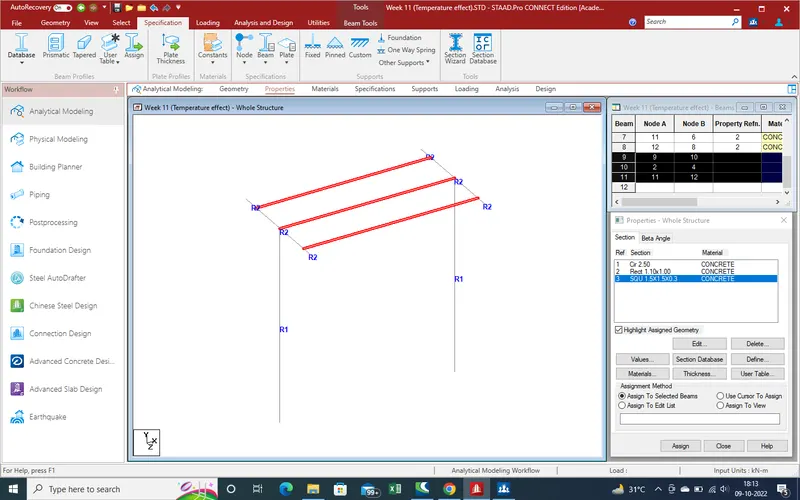
Assign the properties
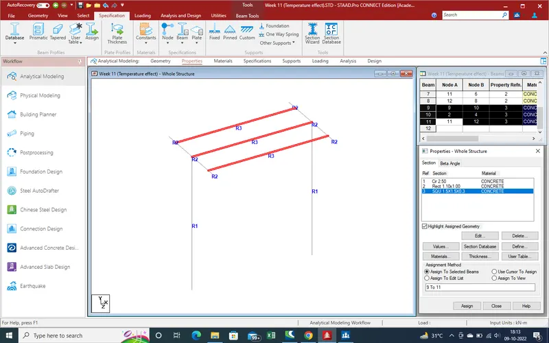
12.Now create the slab and apply the properties .
As per given data our slab width is 7 m and cap width is 6 m so need 0.5 m offset in z-direction both side .
now we create new node for create plate section for slab and follow the given below steps
Select the node for translation repeat command as showing in given pic .
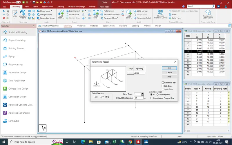
After create node select the 2 outer nodes for translation repeat in X-direction for plate .
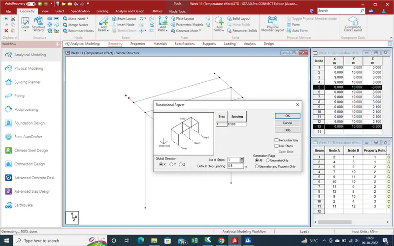
Get the all 4 node for plate section ,now go to "add plate" section .
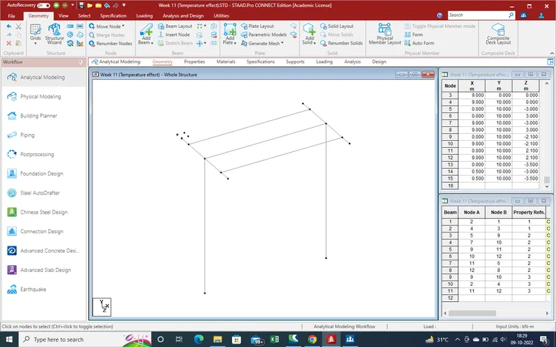
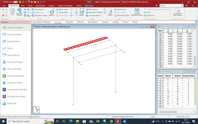
And get the result ,with this plate we use the translation repeat command and create whole slab of bridge as
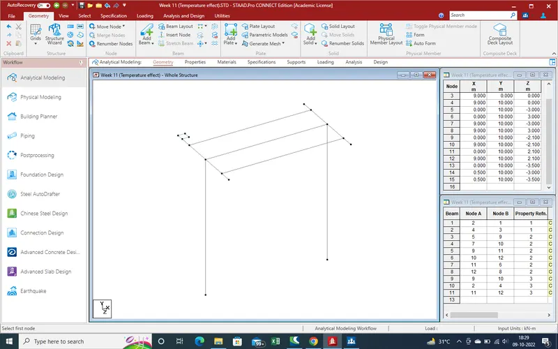
Select the plate for translation repeat command and select the direction as x-direction and no of stepts will 17 due to here span is 9 m and plate width is 0.500m and one plate already created .
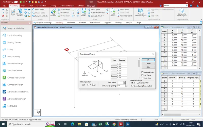
And get the results as showing as ,
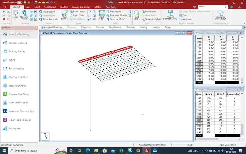
Now again select the longitudanal direction plates for z-direction plates create. As width of slab in Z-direction is 7 m and length of plates is 0.5mm and one lane alteady created so we need 13 steps so put the values as 13 in Z-direction .
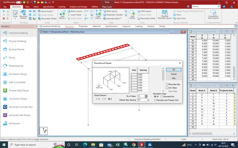
And get the results as showing .
Now we Apply the plates properties and assign as given below steps
Go to properties section and select "Plates thickness". a new window has been open as showing .As per given data slab thickness is 0.550m so put the values of thickness is 0.550m and add
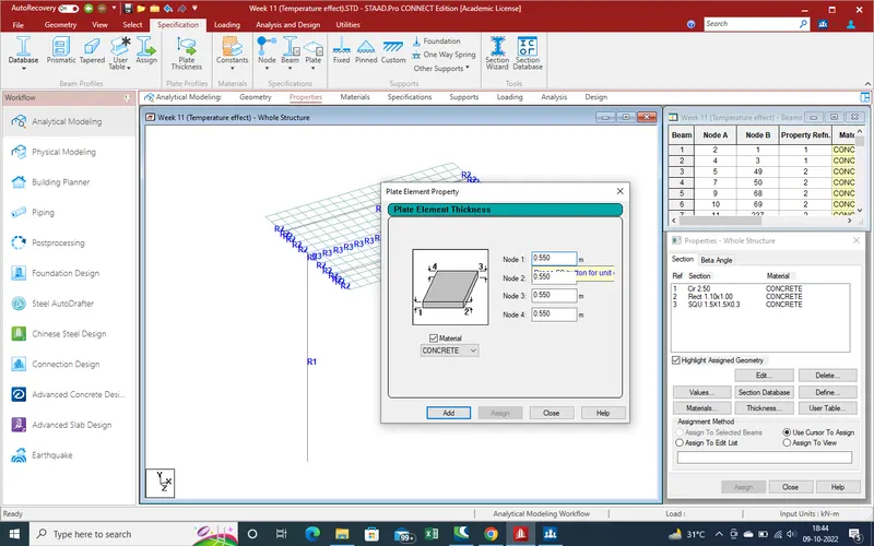
After close the secondary window select the plates where we need to apply the properties as showing in given below pic .
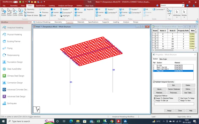
As we assign ,will take confirmation
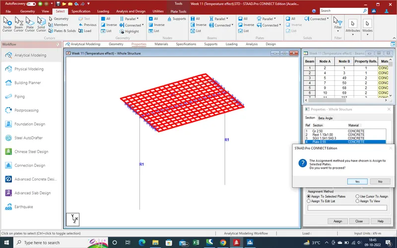
And get the results as showing .
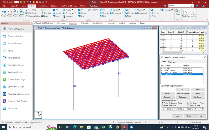
13.Now apply Support reation as fixed support at end of pier location .
As we select the support section a new window has been open as showing .
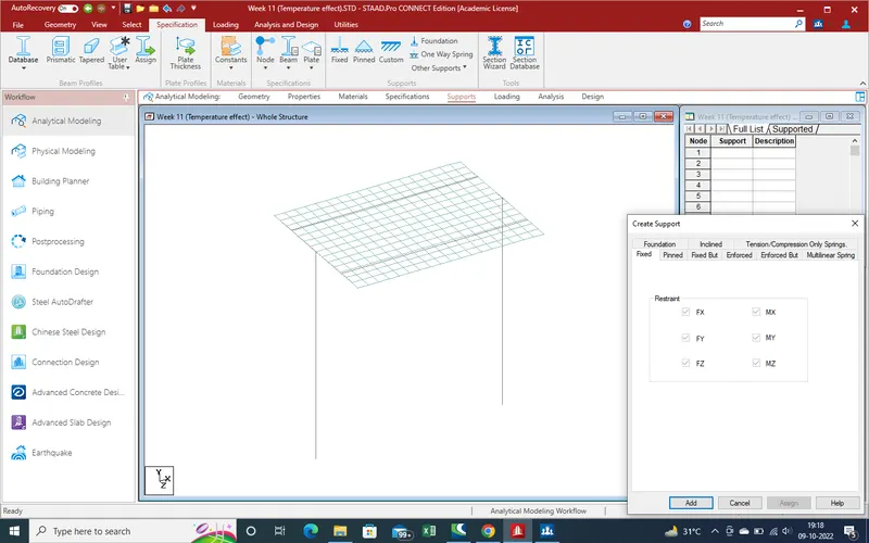
As support are fixed support so select the fixed support and add .
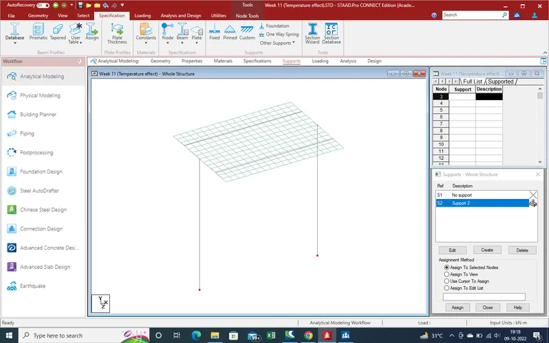
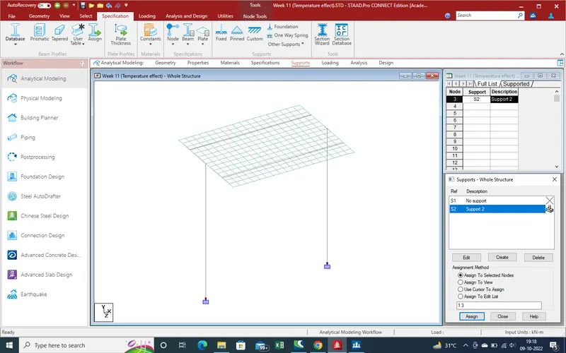
New support property has been created ,now need to select the node where we apply the reaction .
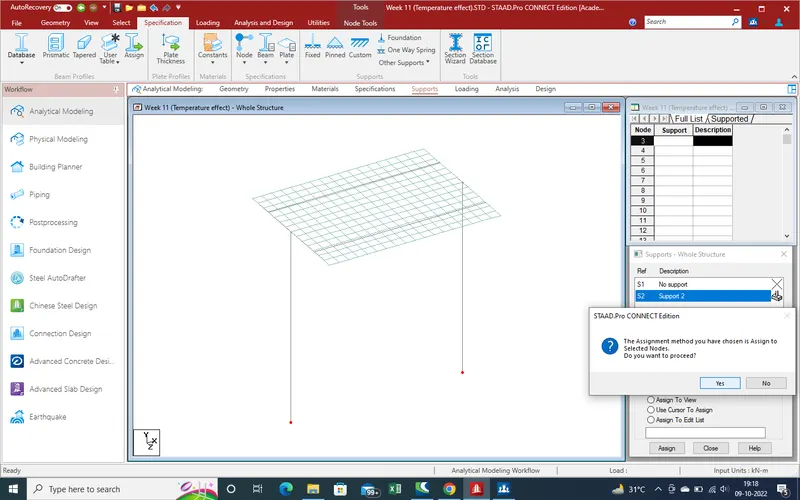
And get the results as showing .
14.Now we apply the loading ,as here loading is "Temprature loading".
For loading apply on bridge we follow given below steps .
Go to loading section ,and select the load case details and add new.
as showing a new window has been open "TEAMPRATURE LOAD "
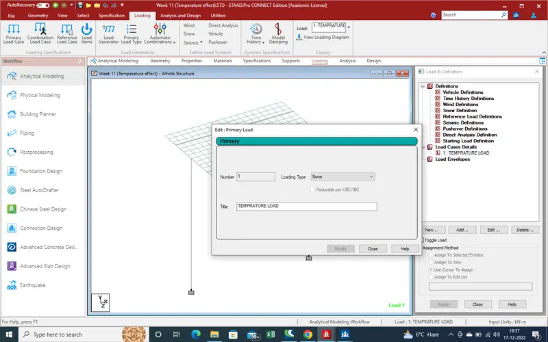
Again select the add a new window has been open such like .Now need to select the temp load . select the temp load .
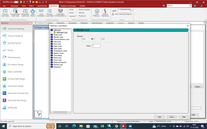
As select the temp load a new window as been open such showing in given below pic. Here we select the Temp , in which we need 3 values as . 1. Temp change which is 35.3 degree which we calculate in starting . Second Temp diff. from top bottom of deck slab which shall be calculate by given Is Code graphical code from +ve temp differance
as
top temp - 48.4
for bottom
(from graph )
=(2.1/17.8)*48.4
=5.71 degree
So , differance of slab
=48.4-5.71
=42.69 degree .
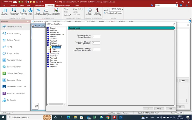
So , put the above calculated for given window and add.
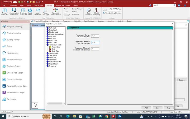
Click on Add and close the window
Now modelling and load application work has been complited . now run the model and get the results as
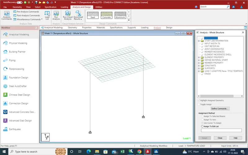
perform the analysis
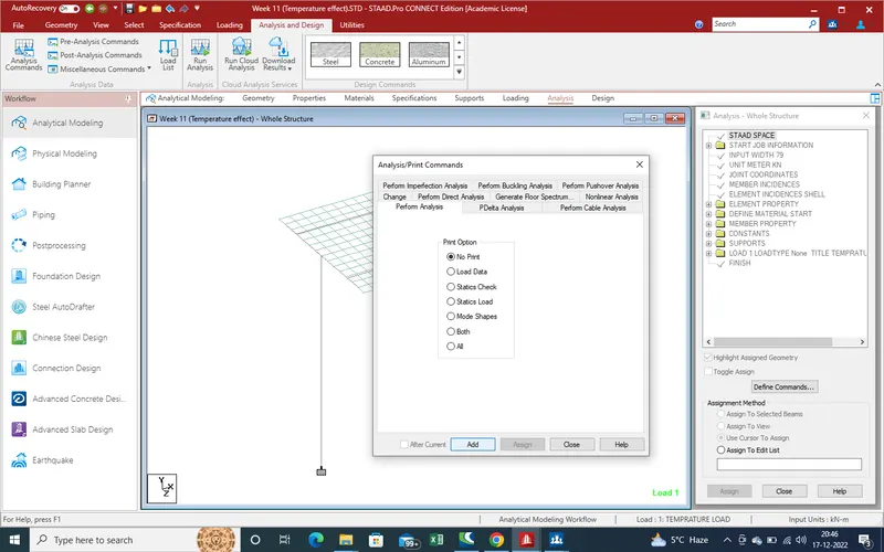
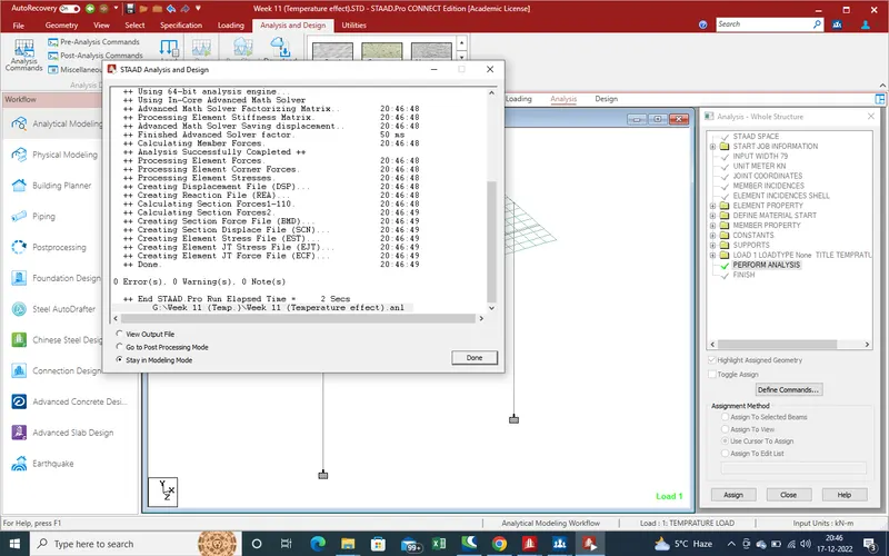
Run the analysis . There is no errow so model is ok . Now we get the results .
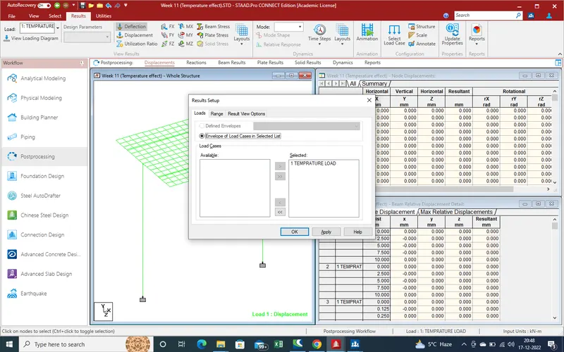
RESULTS:-
We get the results as showing
As here get the displacement due to temp load over the bridge .
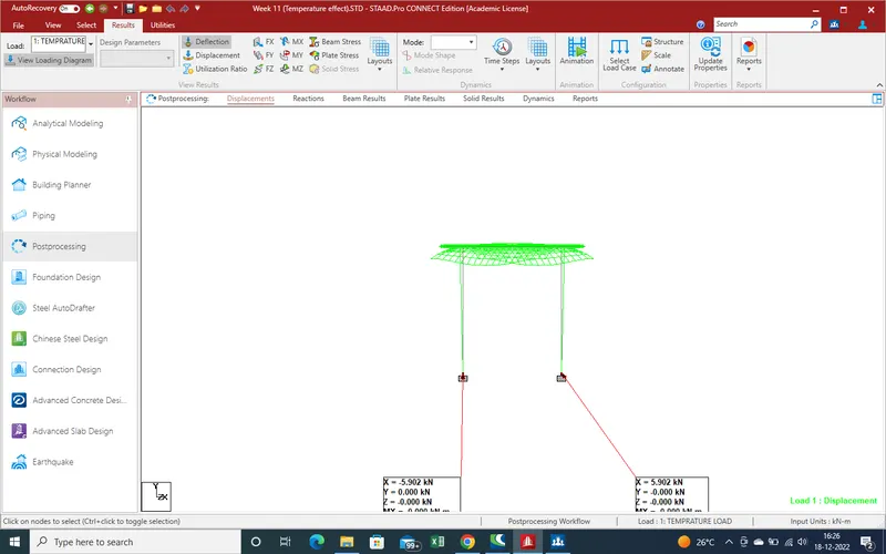
Displacement in x-direction
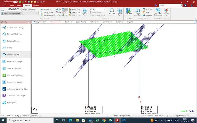
Displacement due to shear in y-direction
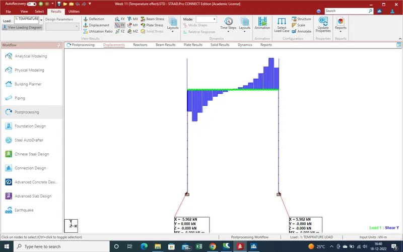
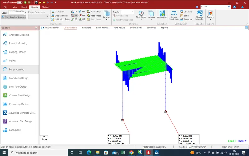
Displacement due to shear force in X-direction .
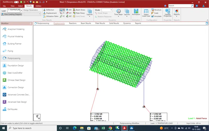
Moment in X-direction
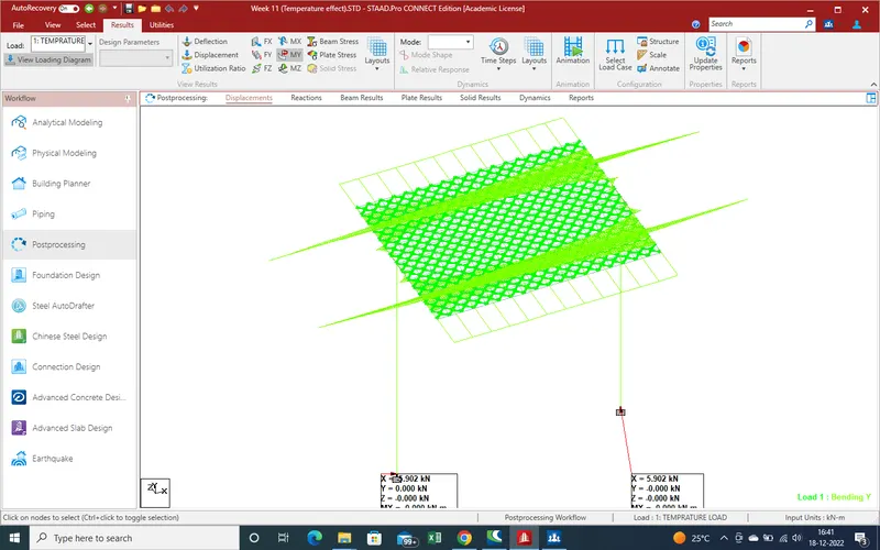
Moment due to temp in Y-direction
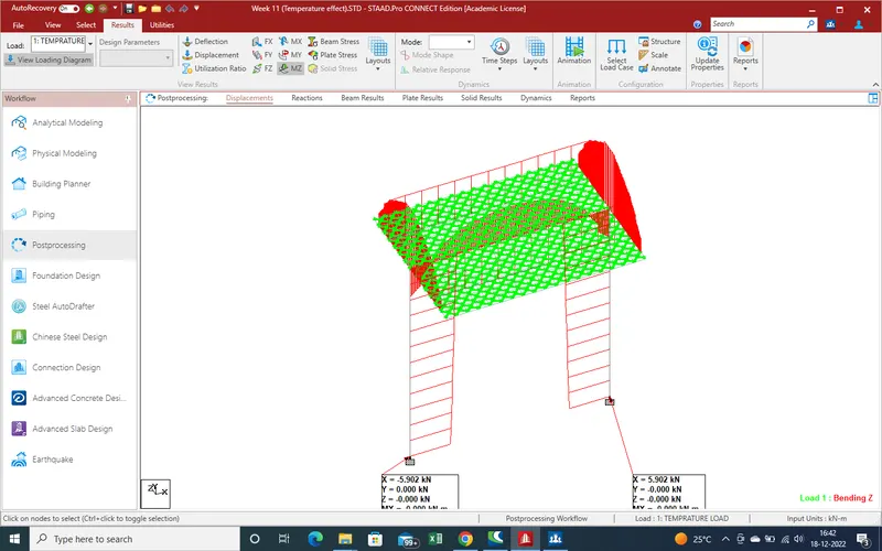
Moment due to temp in Z-direction .
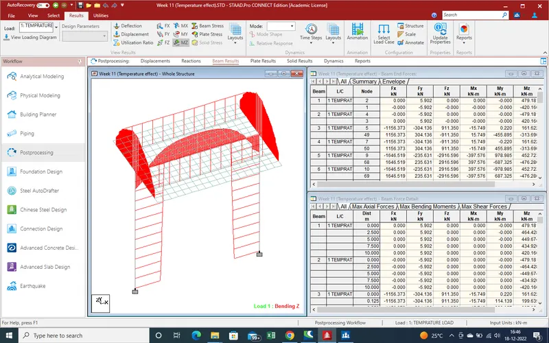
Beam stress

Moment in Z-direction
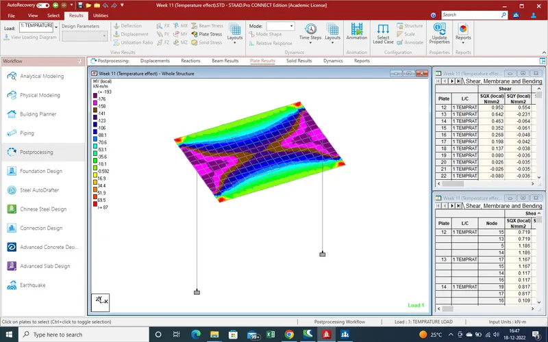
Plates moment due to temprature
Conclusion :-
As above, we get the temp effect with the help stadd pro and get the results.