Week 5 Challenge
1.Aim :-
The main purpose of wind load consider is to find out the effect of Wind on Bridge with the help of IS Code 875-2015. With the help of IS code We can find out the forces resultants apear on bridge due to wind.
2.Introduction :-
In this problem there we find out the effect on bridge due to Wind load, in which wind speed will depend on location as there location is located at Mumbai,with the help of IS code 875-2015 (Part-03) effecting componet find out and get the critical value for save the structure damage due to wind load.
3.Procedure :-
To find out the effect of wind load we need some data like location , type of structure and height of structure like etc . As here some Data are given as
I.Basic wind speed(Mumbai)- 44m/s (As per Is Code)
II.Height of bridge - 10m
III.Span of Bridge -25m
IV.Width of Bridge -10m
V. Size of Pier -1.5*1.5m2
VI.Geometry of Pier - Recangular
VII.Type of Foundation -Open Foundation
VII.
Now we find out the Design Wind Speed with help of IS code and Given Basic Wind Speed .
As Per IS code Design Wind Speed
Vz=Vb*K1*K2*K3*K4
=44*1.07*1.05*1*1.30
=64.264m/s
here ,
K1 -Risk factor.
K2 -Terrain roughness and height factor
K3 -Topography Factor
K4 -Importance Factor
Now from Design Wind Speed we find out wind pressure Pz
As per IS Code ,
Pz=0.6Vz^2
=0.6*64.264^2
=2.478Kn/m2
Here ,
Vz-Design Wind speed
From Wind pressure we can find out the Design wind pressure which can be find out such as
Pd = Kd*Ka*Kc*Pz
=0.9*1.0*1.2*2.478
=2.676 Kn/m2
Note Pd value should not be less than 0.7*Pz
here ,
Kd- Wind directionality factor
Ka-Area averaging factor
Kc-Combination factor
this value shall be use in Staad Pro for wind load effect on bridge.
Now we Draw the model in staad pro and apply the design wind pressure which we find with the help of Is Code 875(part -III)
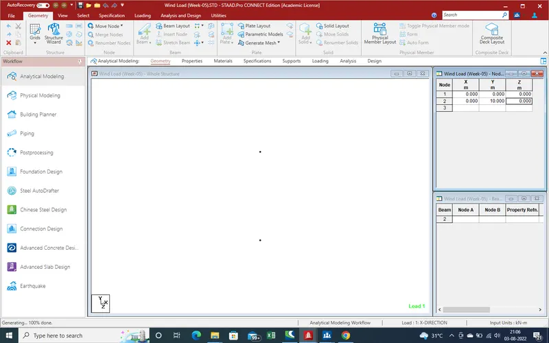
1.Open Staad pro and and Create a folder as wind load as showing in given pic.Create 2 node Y-Direction Spacing 10 as pier shaft height is 10 m .
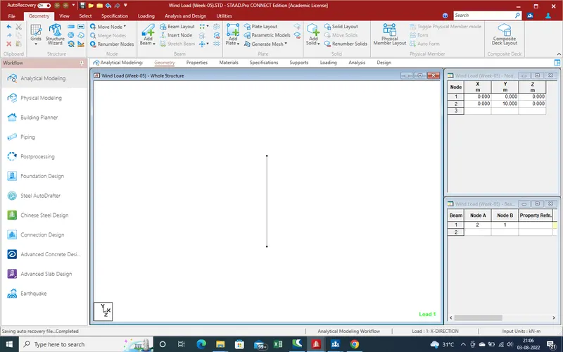
2. Now Create Beam from foundation as showing in given pic.
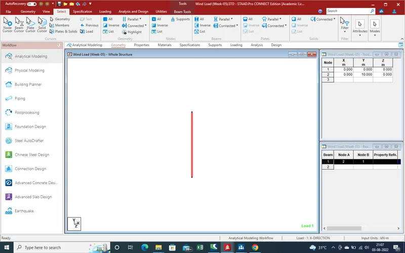
3.Select the Beam for translation Reapt in X-Direction and Z-Direction respectively for pier create
4.As bridge width is 12 m then in Z-Direction and spacing shall be 12 m for create second pier.
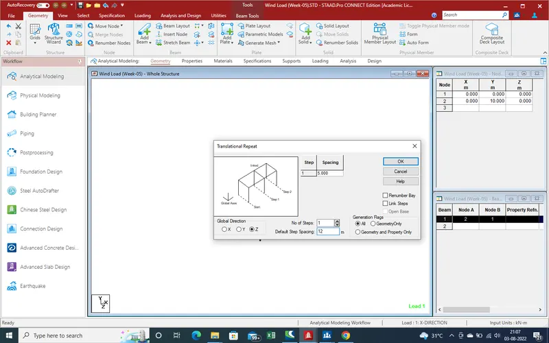
5.As select the values for translation Repeat.
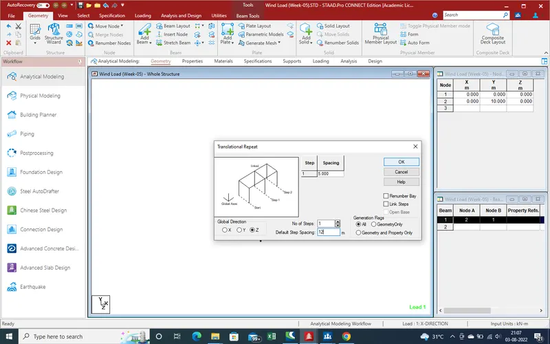
6.We get the result the translation repeat in X-Direction as length of bridge is 25m.
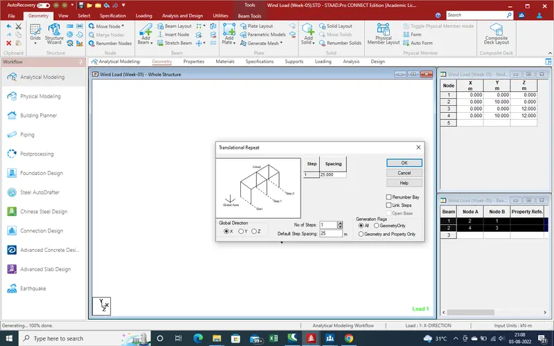
7.Create the Main Girder and Cross girder with help of Add beam command for quick create beam.
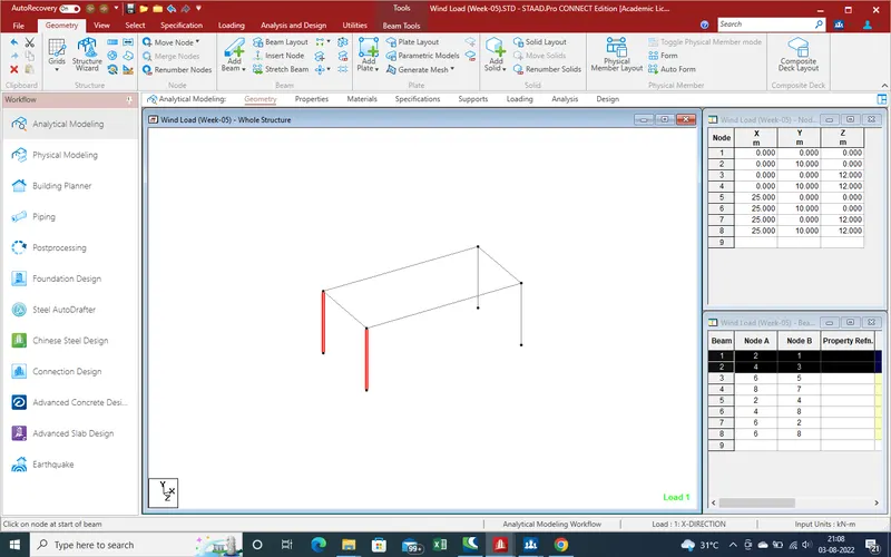
8.We get the results as shown in given pic.
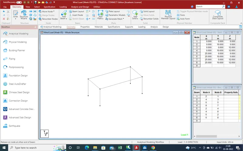
9.Now need the main Girder at 3m spacing so need again translation repeat command as showing in given below pic select the beam which we want to repeat
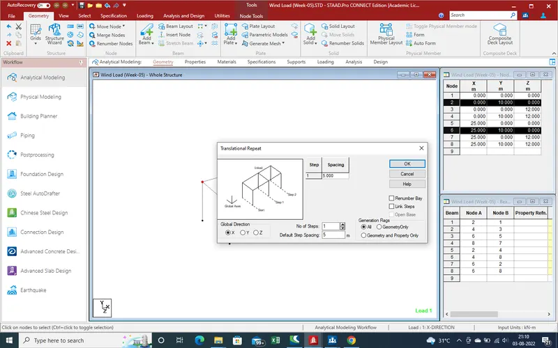
10.And get the result as shown as in Z-direction
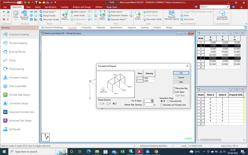
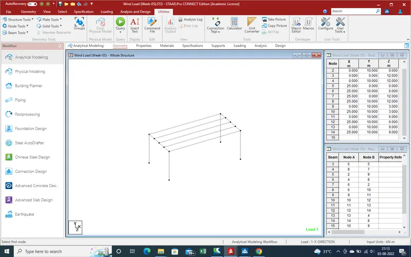
11.And we get the results as shown in below -
12.Now need the create the properties for beam for Pier ,Main girder cross girder and Plates
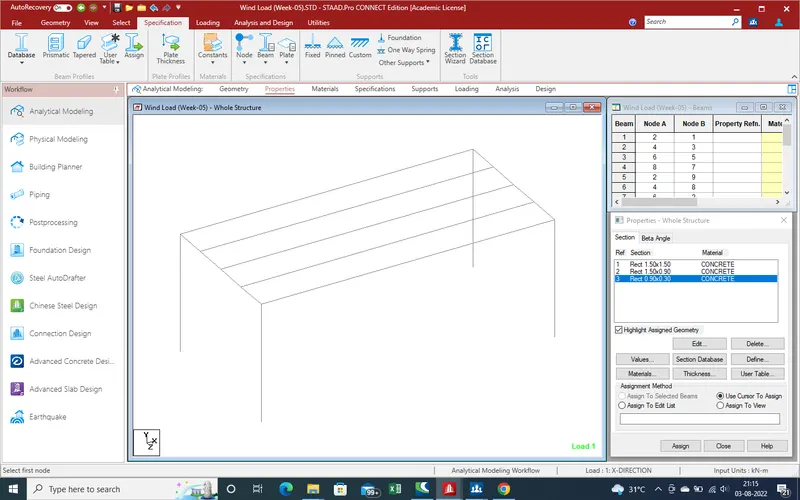
13.Select the main Pier as them size as 1.5*1.5m2 and select the properties for assign as showing in given below pic.
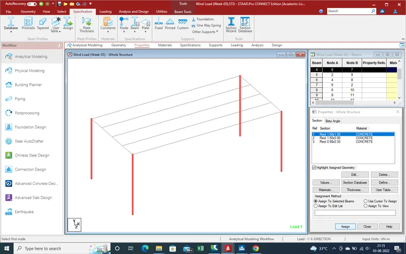
14.Properties has been applied .
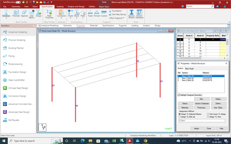
15. Now Select the properties for main girder for apply on main girder as showing in given pic , select the main girder for assign as showing .
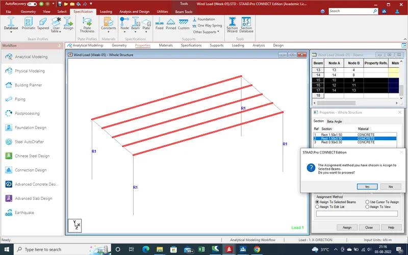
16.Now select the Cross girder for assign for properties as showing in given below pic .
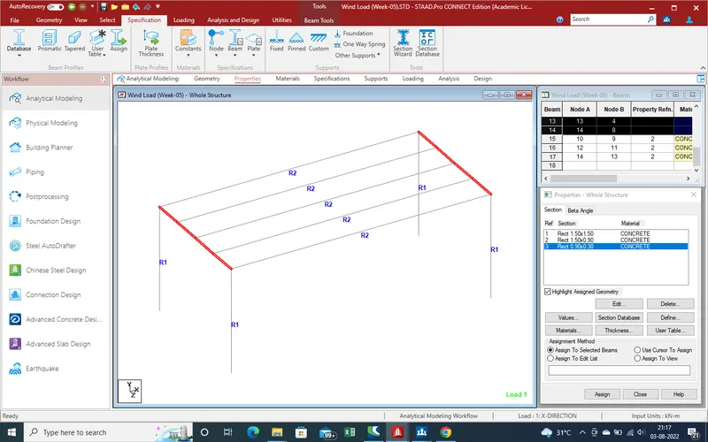
17.We get the results as showing in below pic.
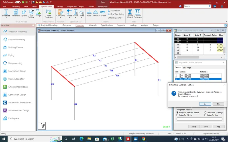
18.
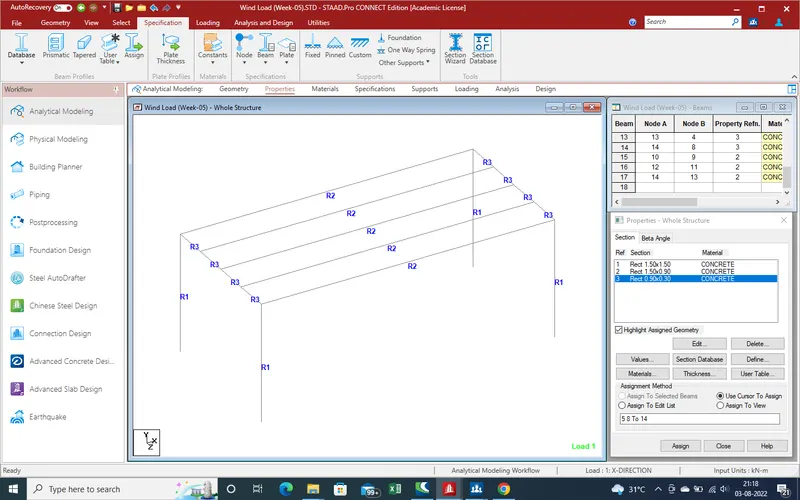
19.Now need the create the slab as small plates section , so need the plate section on the main girer so need the nodes for plate section. so select the node cruser and use of translation repeat command for create the node over the girder as showing in pic.
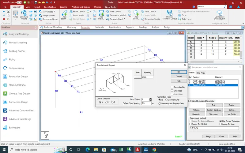
20.We get the node in X-Direction and we now same node in Z-Direction withthe help of node translation repeat command .
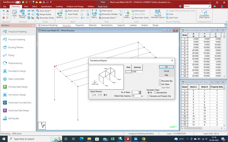
21.Results are as expetion, Now need 0ne more in X-Direction
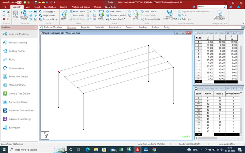
22.Now we have 4 nodes for create the node as shown ingiven below pic .
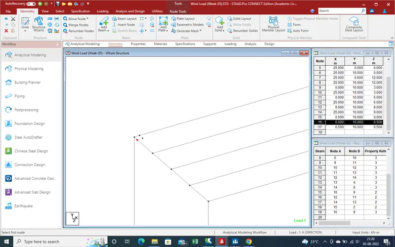
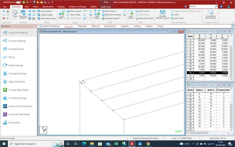
23.Now get the one node ,with the help of translation repeate command we can easly create over whole slab plate node .
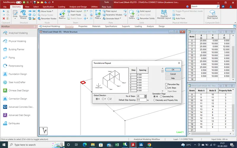
24.Select the plate for translation repeat command as length of bridge in X-Direction is 25 m so there is no of steps of 0.5 m is 49 no .Put the values in step is 49 and spacing is 0.500m
25.Now we get the results as showing in given pic as whole row has been created of plates section.for whole plates create in Z-Direction.
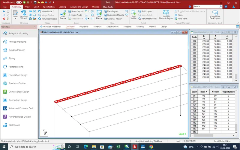
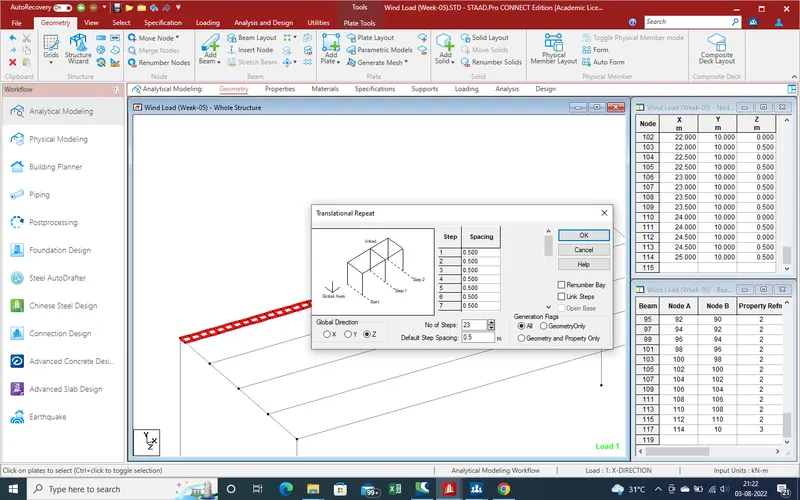
26.Select the Direction as Z-direction and no step as 23 due to bridge width is 12 m and spacing is 0.500m and click on "ok".
27.We get the plates section over the whole slab as showing in given pic. Now we need the apply the properties for applying on the plates.
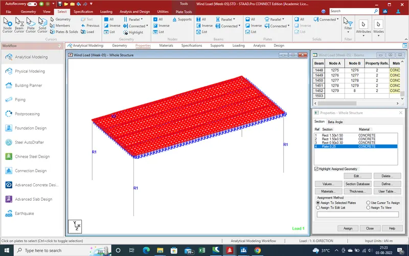
28.Select the Properteis as plates thickness as 0.220m and slect the properties and after that slect the plates over which we want apply properties .
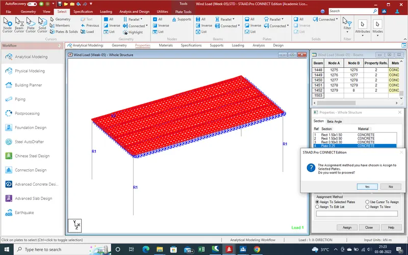
29.Now Apply the support as we assume that pier has fix support reation .
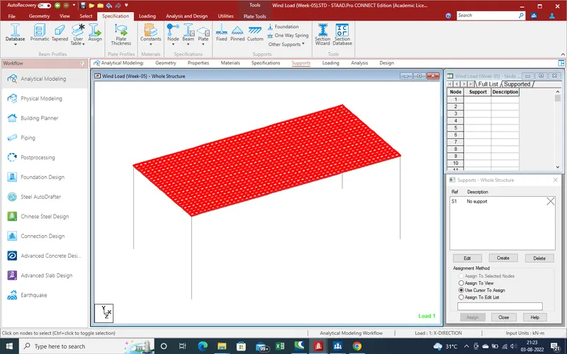
30.Create the fix support as showing in given pic .
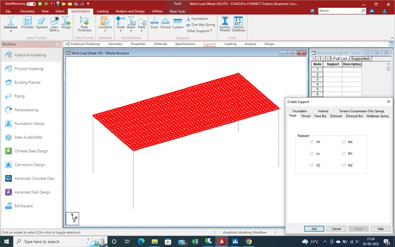
31.Select the node where we need the apply the support reaction.as showing in given pic we select the pier bottom node for support reation
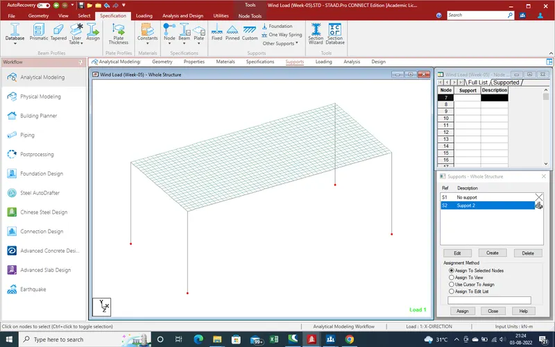
32.
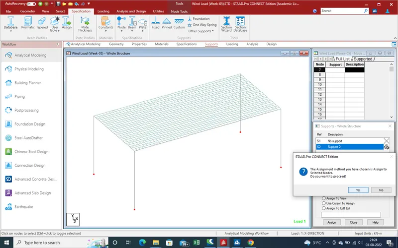
33.We get the results as showing in given below pic .
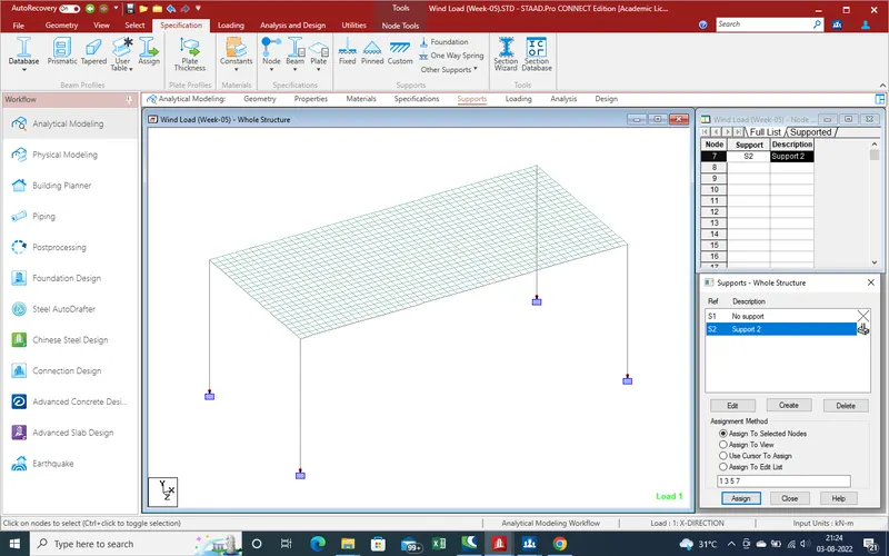
34. Now need required the loading of load as here we apply the wind load on bridge which showing in given pic .
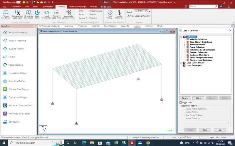
35.Define the wind load defination add the load.As for go to Defination section of loading as showing in given below pic .
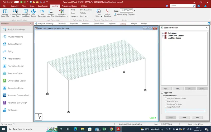
36.Go to Defination Section for define the load which one we considering as here we calculate the wind load.Select the wind Defination and click on "Add" for add wind load condition.
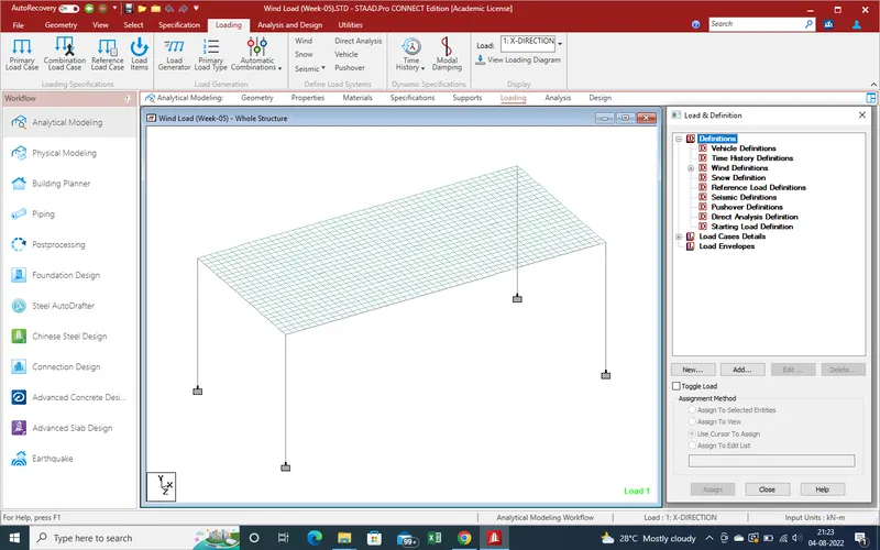
37.Select the wind load and click on "add". After click on add there is an new window has been open which is such as Showing in given below pic.Here we Write the wind load .
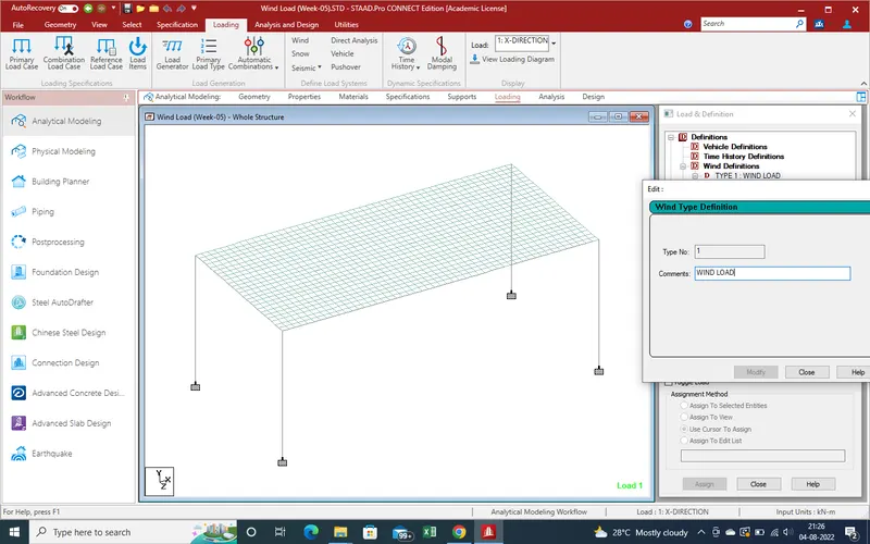
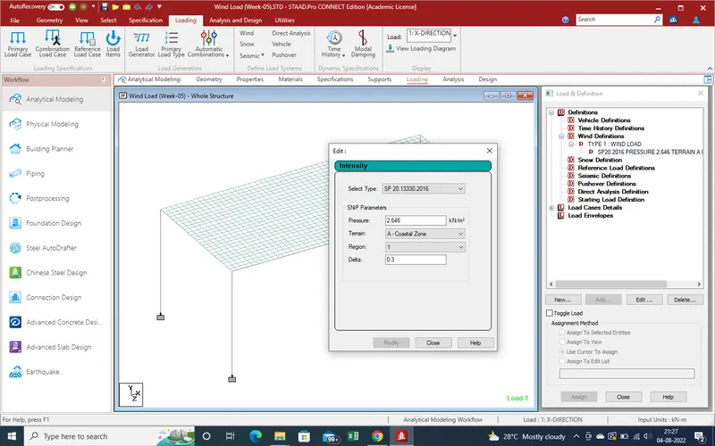
38.Click on "Add" and close the window and we get the new load as showing in defination section of wind load.here Select the type of wind load as we consider SP-20 2016 for Indian code .
39.Now We Select the Design wind Pressure as we define in starting as 2.676Kn/m2
40.Now Need the Select the Terrain from given type ,As Mumbai near the sea so terrain is A-costal Zone .
41.We assume that the region is open area there is no obstraction so select the region is 1.
41.As perviouse section define that the area is open then the angle of delta is less than 0.3
44.Click on Add and Close the window ,The Defination has been Added as wind defination as given below pic.
45.Now Select the Load case as Direction of Load on given section .
46.Click on Add Section and get the new window as showing given below section.
as here we first consider as +X-Direction and Add and Close and get the case type in load cases .Same condiser for -X-Direction and +Z-Direction and -Z-Direction cases .
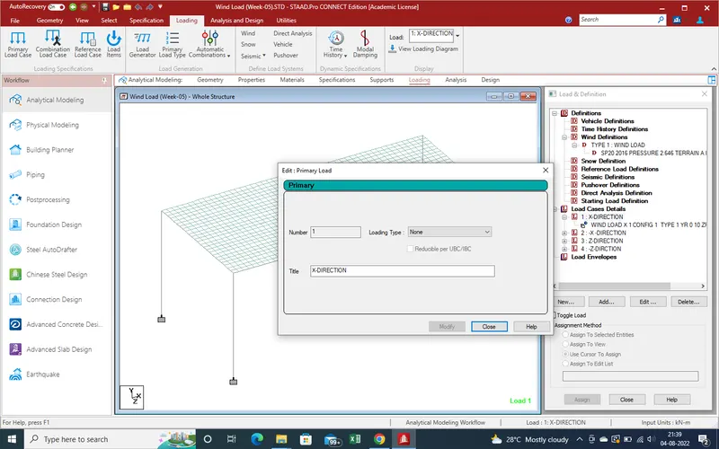
47.We get the all load cases for loading .
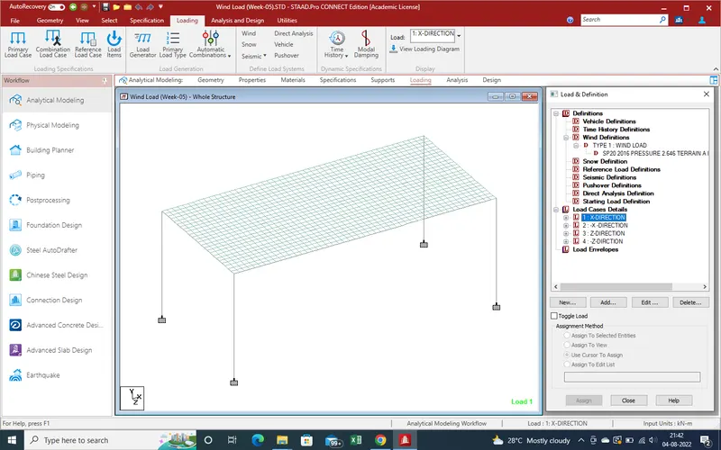
48.Now Select the X-Direction Load case and Click on "Add" for fixing the loading area where the loading will directly effect the bridge . as for +X direction the bridge in Y-Direction and Z-Direction area define require .as here +x-Direction Y-values is 0 to 10 and Z-Direction values are 0 to 12 and there is no need the X-Direction values as starting values are 0 ,0 so put the values as we define and select the direction as X-Direction as given below pic and click on Add and close the window .
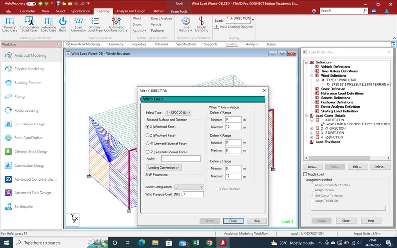
49.And we get the loading area as showing in given pic.
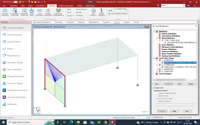
50.Same as for -X-Direction and +Z-Direction and -Z-Direction as given showing given below pic .In (-)Negetive Direction values we need the put the values as -1 for factor as for change the direction of load of wind .
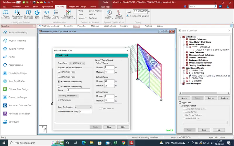
51.For +Z-Direction
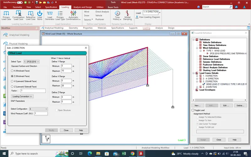
52.-Z-Direction Loading .
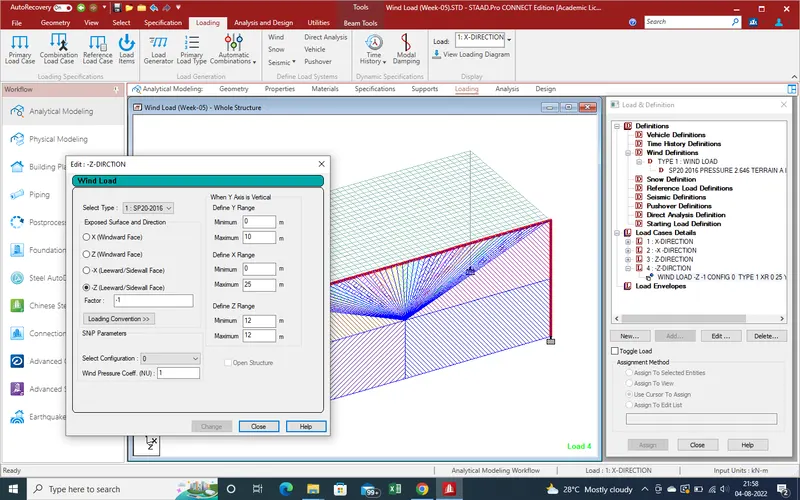
53.Loading
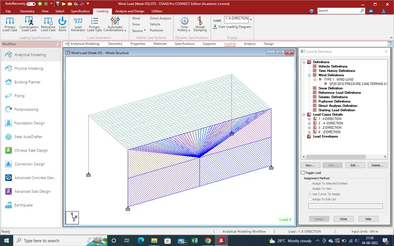
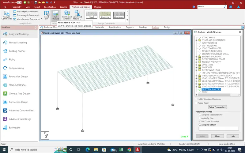
54.Now All Modeling work has been complited. Now need the Run the Analysis model .
Go to Run analysis section select the "Run Analysis" and get the results .
55.Now after run the analysis we get the no error as showing given below pic.
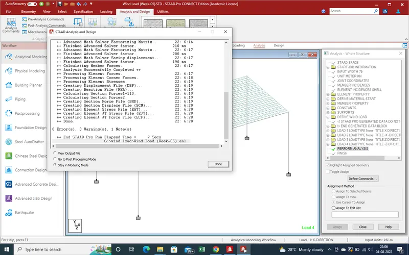
56.Select the all load for result of loading due to wind load .
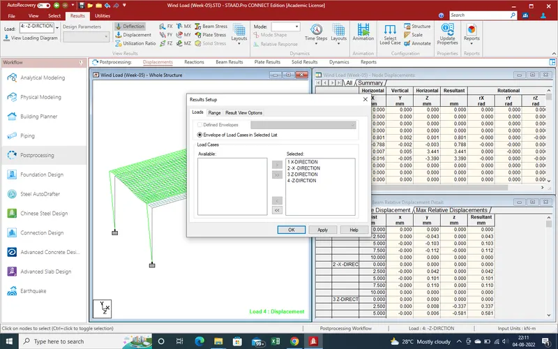
4.Results :-
1.Displacement due to +X-Direction Wind load
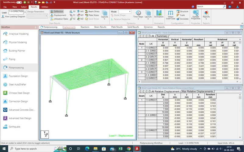
2.Displacement due to -X-Direction wind load
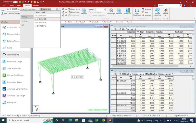
3.Displacement Due to Wind load +Z-Direction
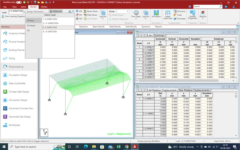
4.Displacement due to wind load -Z-Direction
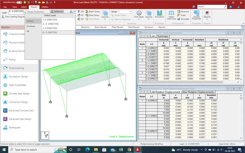
5.Max Node Displacement and Max Beam Displacement due to wind load values .
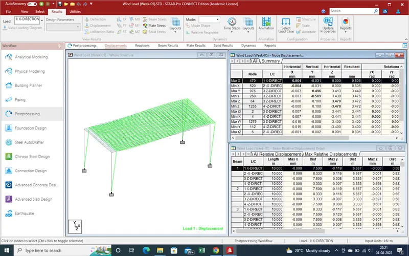
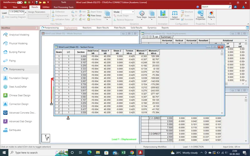
6.Shear Force due to +X-Direction wind load .
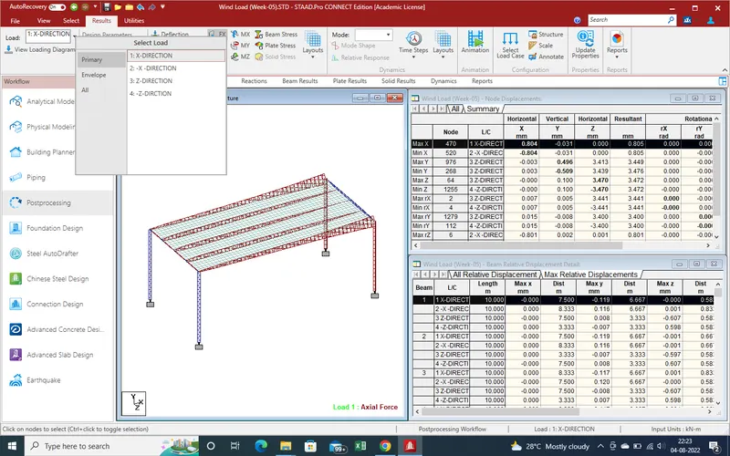
7.Shear force results due to -X-Direction.
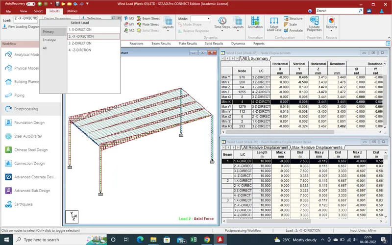
8.Shear force results due to +Z-Direction
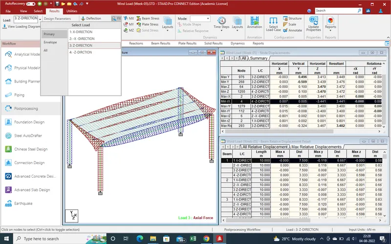
9.Shear Force results due to -Z-Direction.
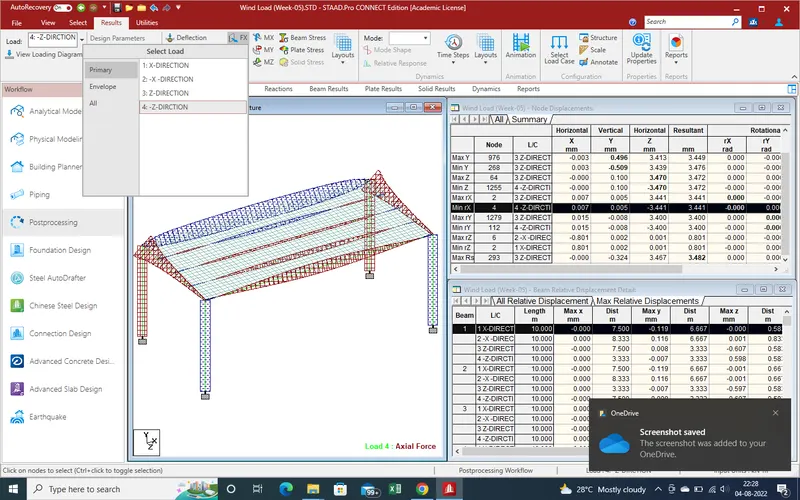
10.Shear forces results due to Y-Direction due to +X-Direction wind load
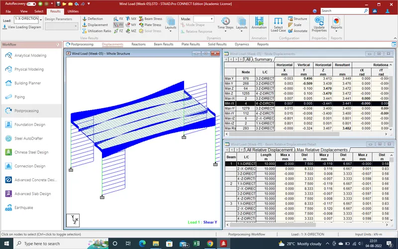
11.Shear forces results due to Y-Direction due to -X-Direction wind load.
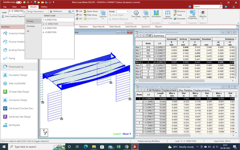
12.Shear forces results due to Y-Direction due to +Z-Direction wind load.
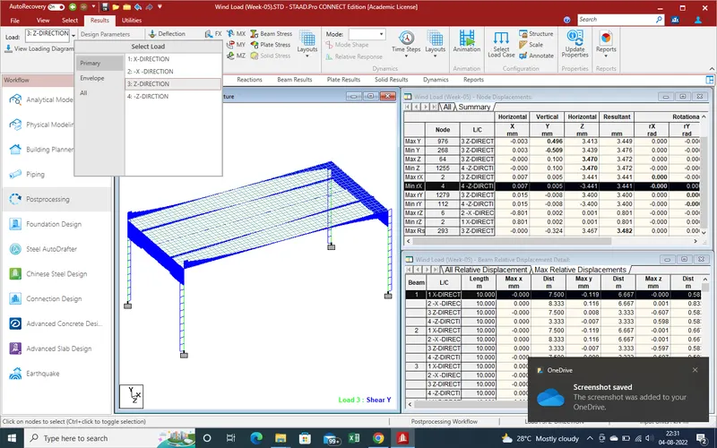
13.Shear forces results due to Y-Direction due to -Z-Direction wind load .
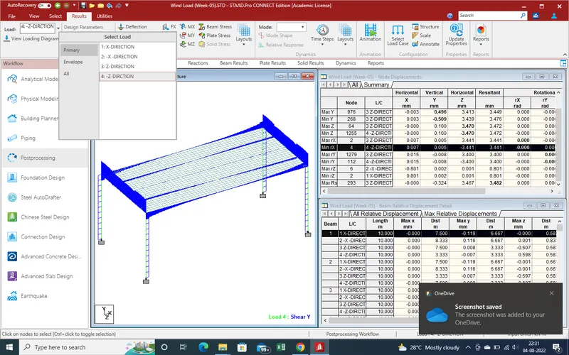
14.Shear forces results due to Z-Direction due to +X-Direction wind load.
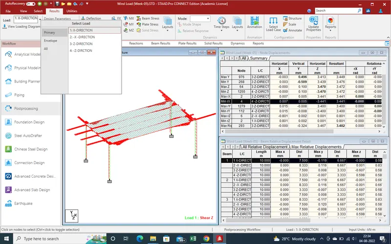
15.Shear forces results due to Z-Direction due to -X-Direction wind load.
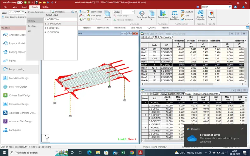
16.Shear forces results due to Z-Direction due to +Z-Direction wind load.
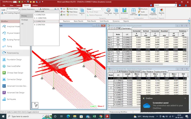
17.Shear forces results due to Z-Direction due to -Z-Direction wind load.
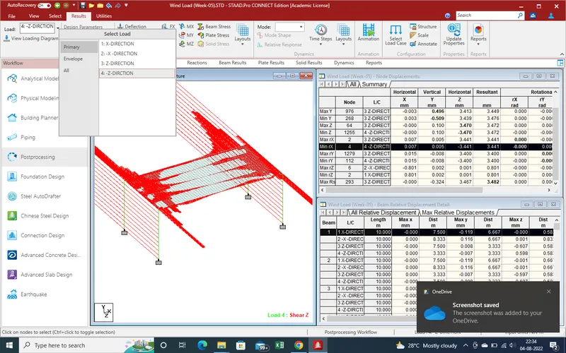
18.Torsion force about X-axis for +X-Direction.
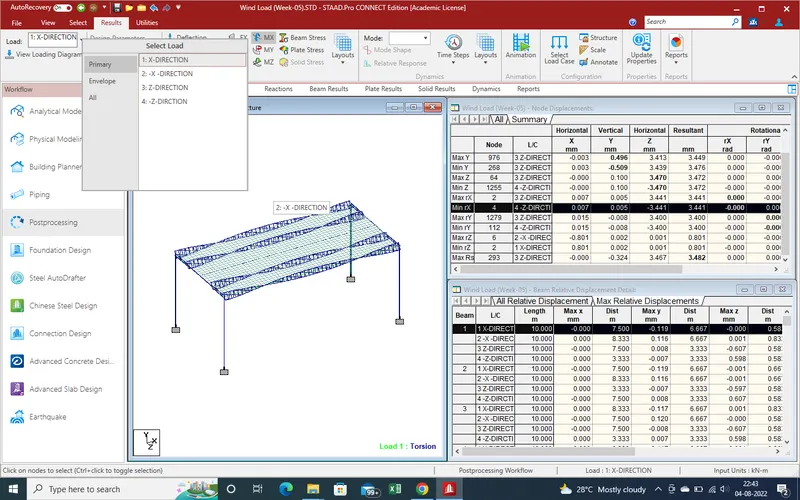
19.Torsion force about X-axis for -X-Direction.
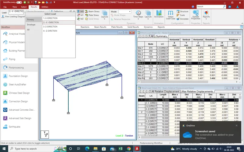
20.Torsion force about X-axis for +Z-Direction.
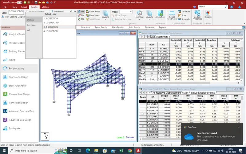
21.Torsion force about X-axis for -Z-Direction.
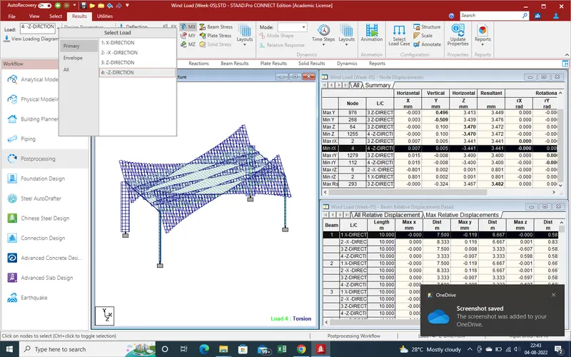
22.Bending Moment about Y-axis for wind load +X-direction.
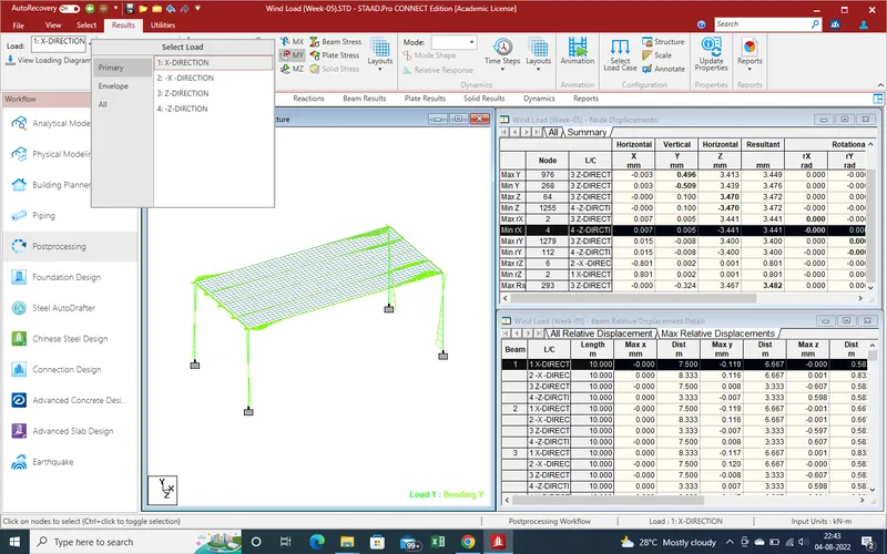
23.Bending Moment about Y-axis for wind load-X-Direction.
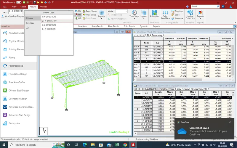
24.Bending Moment about Y-axis for wind load+Z-Direction.
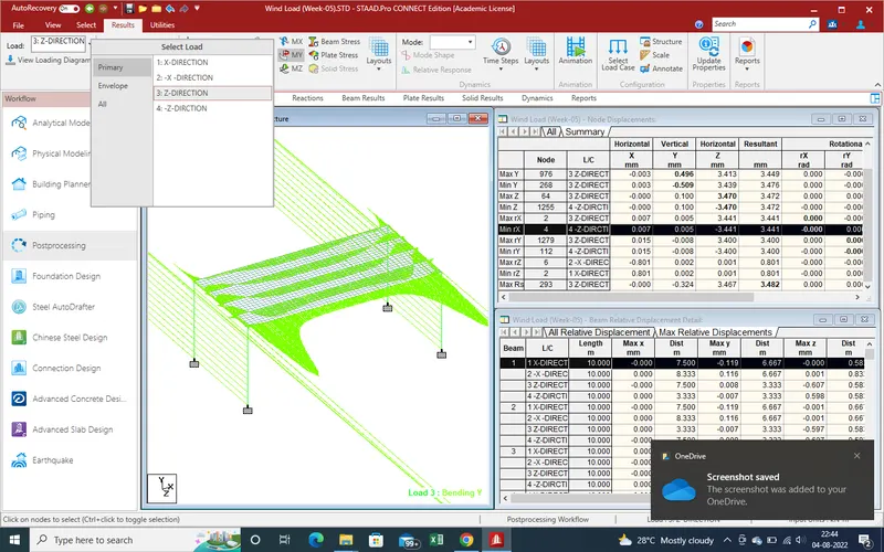
25.Bending Moment about Y-axis for wind load-Z-Direction.
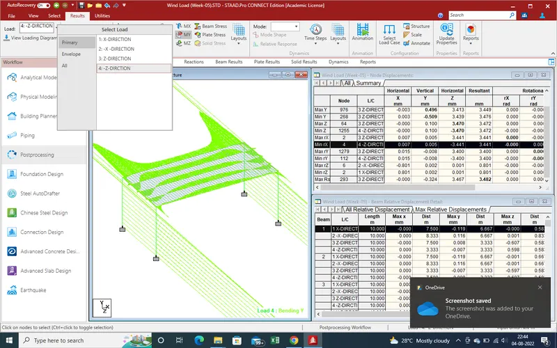
26.Bending Moment about Z-axis for wind load +X-direction.
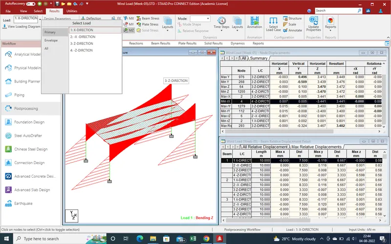
27.Bending Moment about Z-axis for wind load-X-Direction.
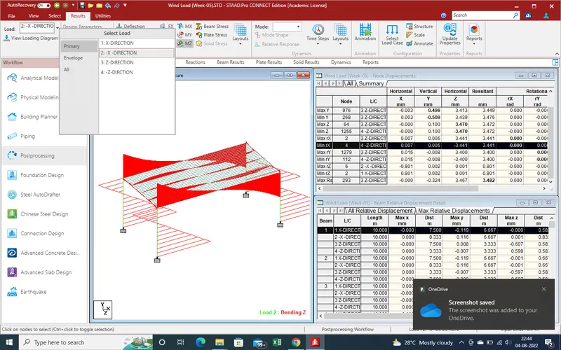
28.Bending Moment about Z-axis for wind load+Z-Direction.
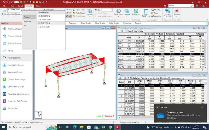
29.Bending Moment about Z-axis for wind load-Z-Direction.
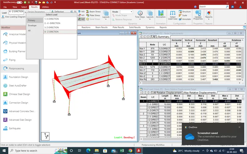
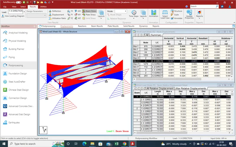
30.Beam Stress due to +X-Direction wind load.
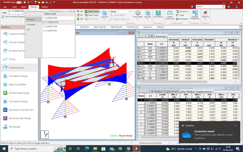
31.Beam Stress due to -X-Direction wind load.
32.Beam Stress due to +Z-Direction wind load.
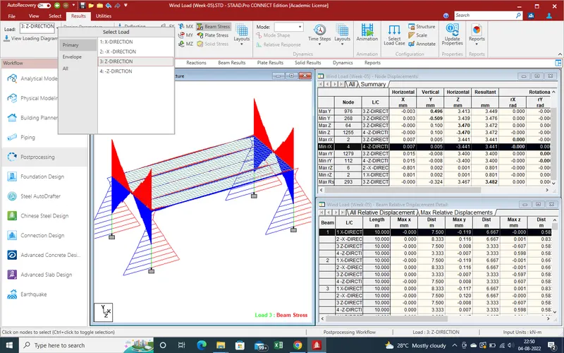
34.Beam Stress due to -Z-Direction wind load.
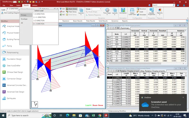
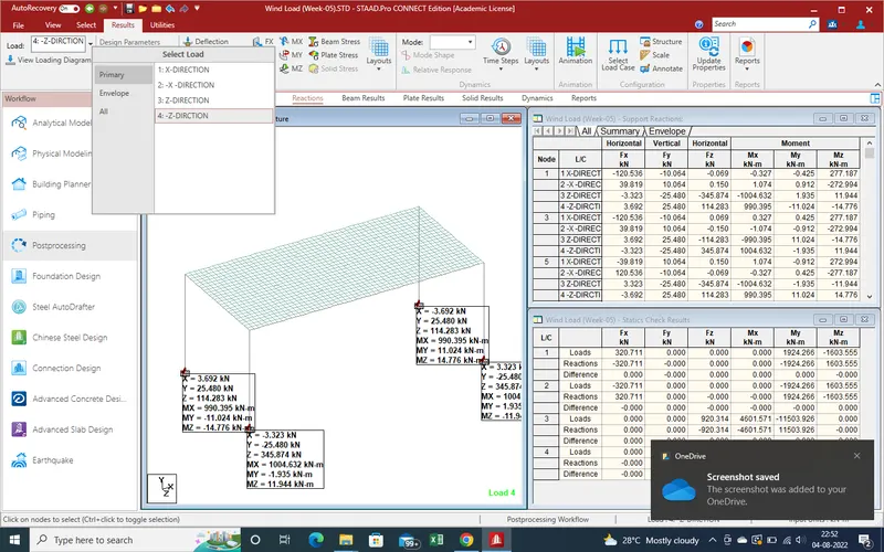
35.Reaction Due to +X-Direction wind load.
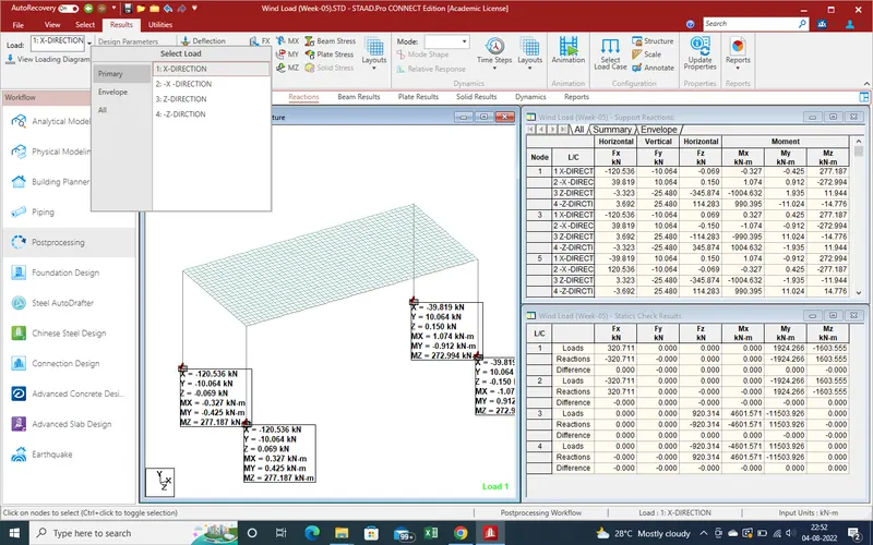
36.Reaction Due to +X-Direction wind load.
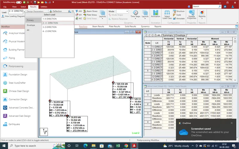
37.Reaction Due to +X-Direction wind load.
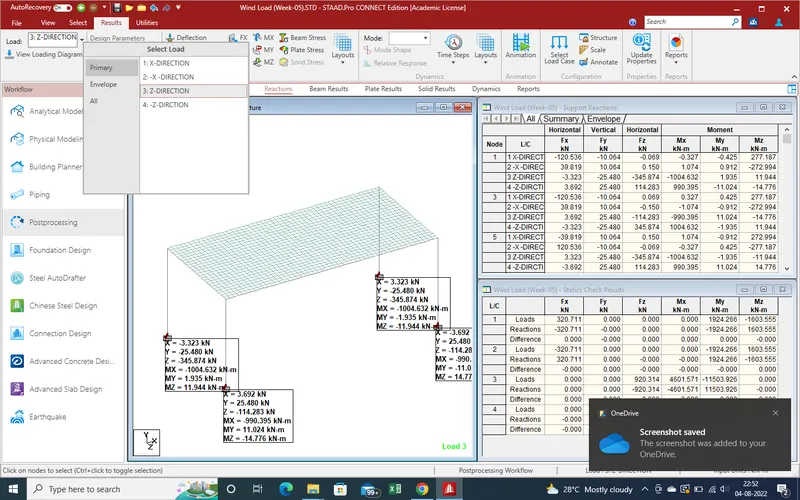
38.Reaction Due to +X-Direction wind load.
39.Shear foeces values
Conslution :-
Now we get the all results from wind load .
here report and Model has been attached .
Thanks with best regards