Week 4 Challenge
Aim and Introduction :-
Earth pressure is an Import Part of loading which,will effect major effect.Earth pressure is the horizontal thrust exerted by the retained earth on a vertical structural element like wall, pier ,Abutment etc.
There is three type of Earth Pressure
A.Earth Pressure at Rest
B.Active Earth Pressure
C.Passive Earth Pressure
Here we Find out the Earth Pressure on Abutment Wall by using the Given Data.
Procedure :-
From Given Data we need to Find Out the Earth Pressure on Abutment wall by using Given Data with the help of Staad Pro.
Here Given Data are such as,
A.Length -05m
B.Backfill soil heigth -07m
C.Ground level from Raft top -03m
D.Thickness of Raft -01m
E.Raft width(Earth face side) -3m (Assumed)
F.Raft width(No Earth face side) -02m (Assumed)
G.Abutment Wall thickness -1m (Assumed)
Now from Given Data we find out the effect of Active Earth Pressure on Abutment with the help of Staad Pro.
Step
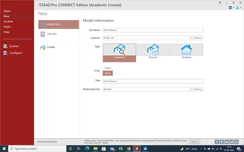
1.First of All need open new file,where will provide the name with appropriate location as here file name "Earth Pressure" location as showing in Pic and unit "Metric" and Click on "Create".
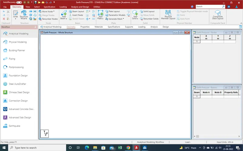
2.Now need Plot the Raft with help of Plate.For Draw the Plate start from node.we start from 0,0,0 as zero or start point.
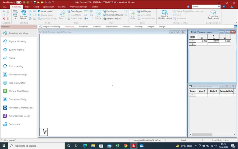
3.After put the value as 0,0,0 and get the node at main screen as showing in pic.
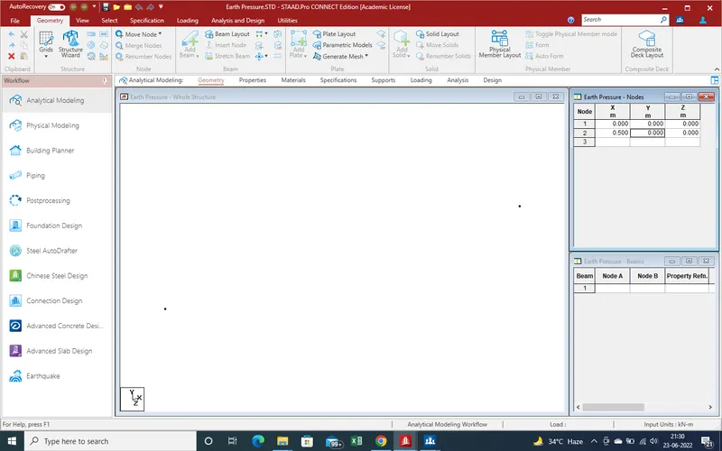
4.As We Assume the plate size of 0.5X0.5m2, so need second node need at 0.5 in x-direction and z-Direction for Draw the Plate.
5.Now need Node in Z-direction ,so we put the node value as 0,0,0.5 and we get the result as showing in given Pic.
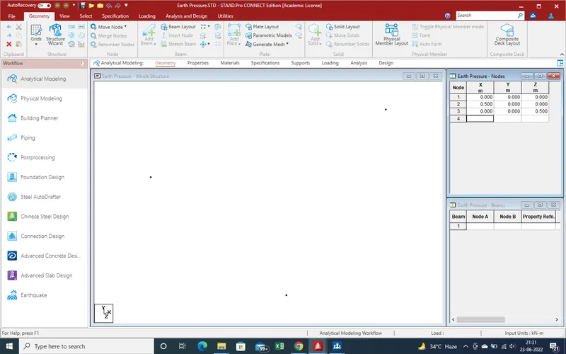
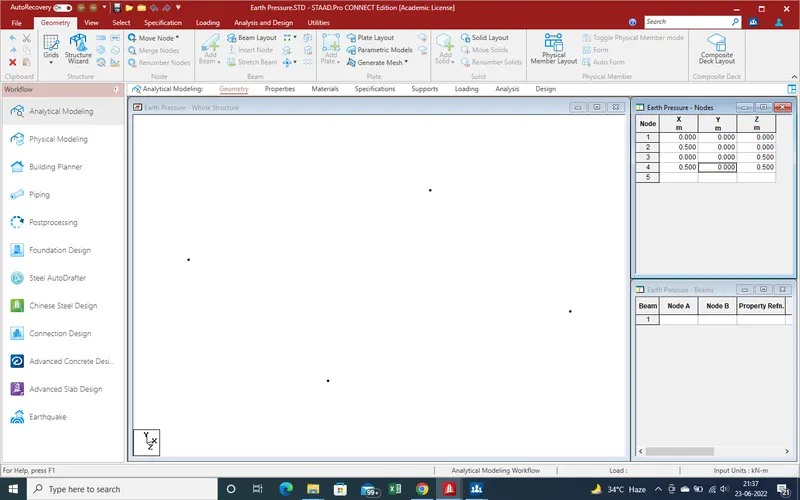
6.Now Last node Required in 0.5,0,0.5 Direction for sequre plate as showing in given Pic and get the required all node for a plate.
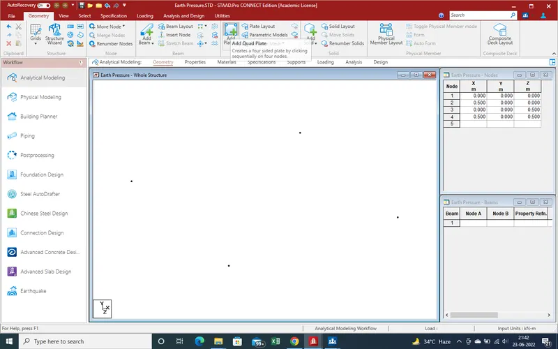
7.Now, Draw the Plate with the help of "Add Plate "Command
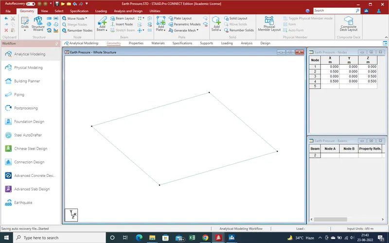
8.And We get the Plate of Size 0.5X0.5M2 Size Plate as shown in given below pic .
9.Now Define the Properties of Plate So when Copy Paste the plate in Different Direction then again need Not to Apply After that .
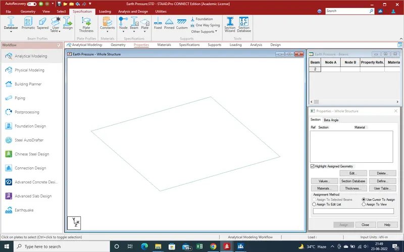
10.Now Go to "Properties" Section and Select the Plate thickness as shown in given Pic
11.As we Select the "Plate thickness " A new window has been Arrived on main Screen as shown given below pic
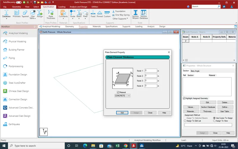
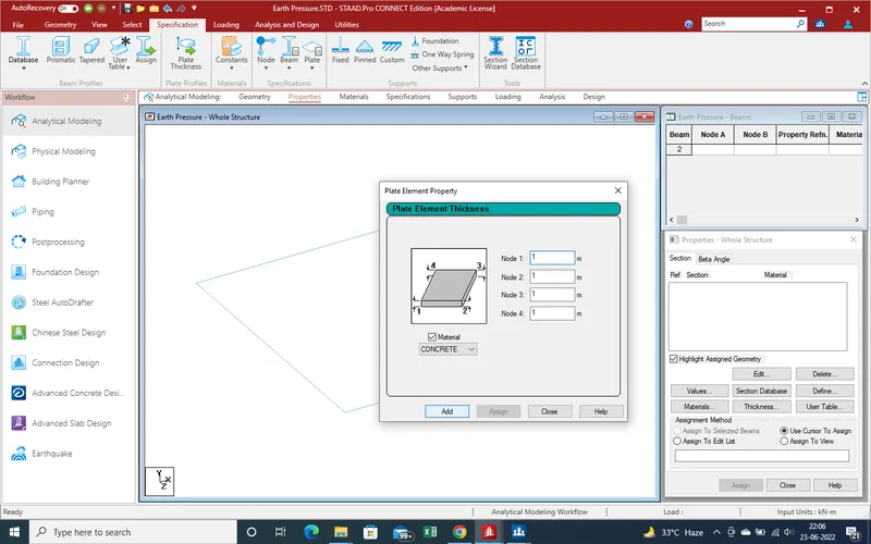
12.Put the value of Plate thickness as raft assume as 1m depth then put the value of Plate are 1m .
after that select the material as here concrete so we select the "concrte " and Click on Addd
13.As we Click on Add Button properties has been added to Side Bar As showing in given below pic
and close the main window task bar .
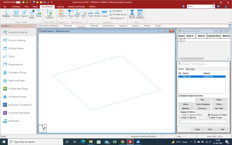
14.Now Select the Plate on which we want apply the property which one we define.For apply the Property on plate, Need the follow given below process
15 .Go to "select" Section and select the Plate Crusor for selection of Plate .
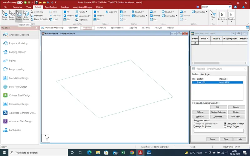
16.Select the Plate on which we want apply the Properties
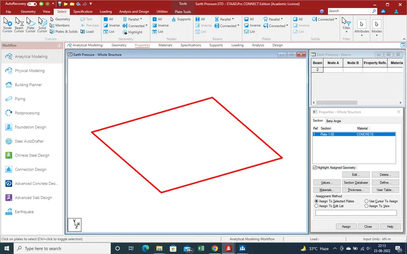
17.As select the Plate the outer line colour has been changed its mean plate has been selected.And With this process , in Properties section "Assign to Selected Plates" has been highlighted as showing in above pic.
18.Assing the property as click on "assign " ,here a new window again arrived for confirmation that is it correct
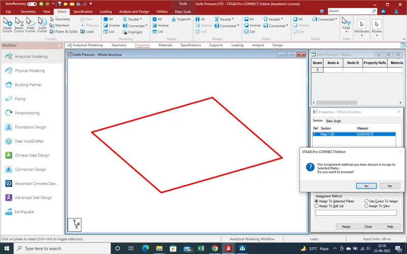
19.Now need the Requirment of Plot the Plate in whole Bottom Area as , We Assume that in X-direction Raft is 6 m and 5 m length is 5 m as given in Data.
20.The use of Translation Repeat command draw the Plate in X-direction as shown in Given Pic
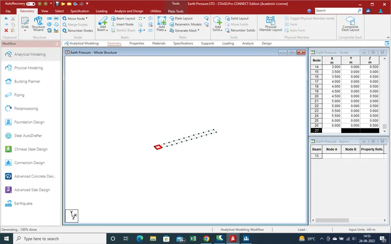
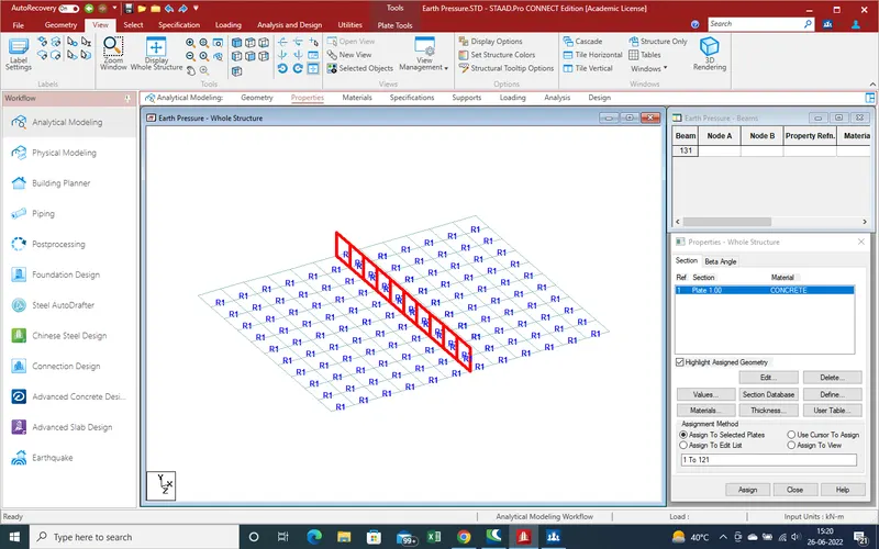
21.Now the Plot in Z-Direction use of Translation Reapt Command and get the result as shown in given pic
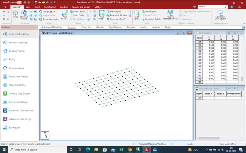
22.Now draw the Abutment wall as plate section of 0.500m *0.500m so we can get the better result in small plates
23.For vertival plate Draw , need 2 nodes in Y-direction ,again use the node translation repeat as showing in given ,
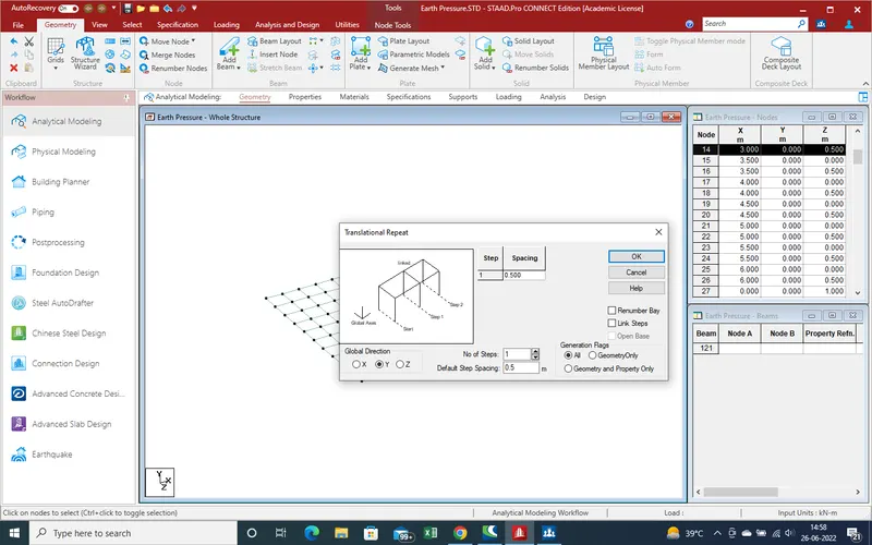
24.After draw the node we can see another section as showing ig given below pic,
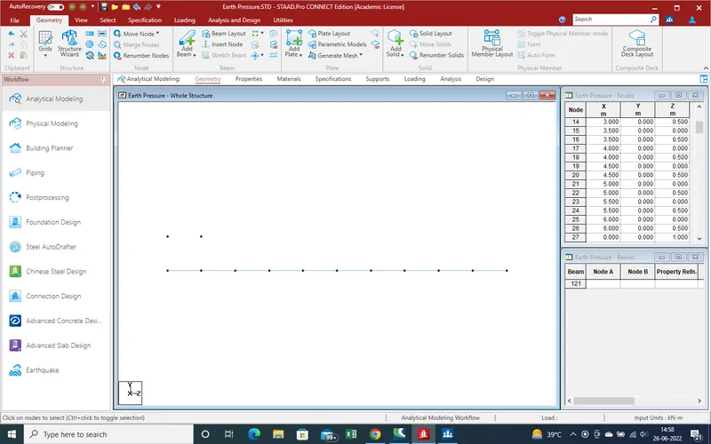
25.Again Draw the Plate with the help of Plate Command as shown in given command
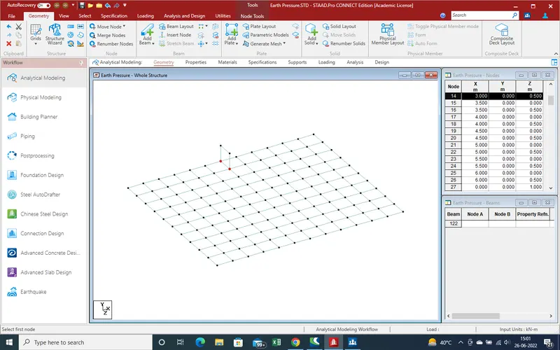
26.Now a plate has been Created , we can draw remaining plate fast with use of translation command
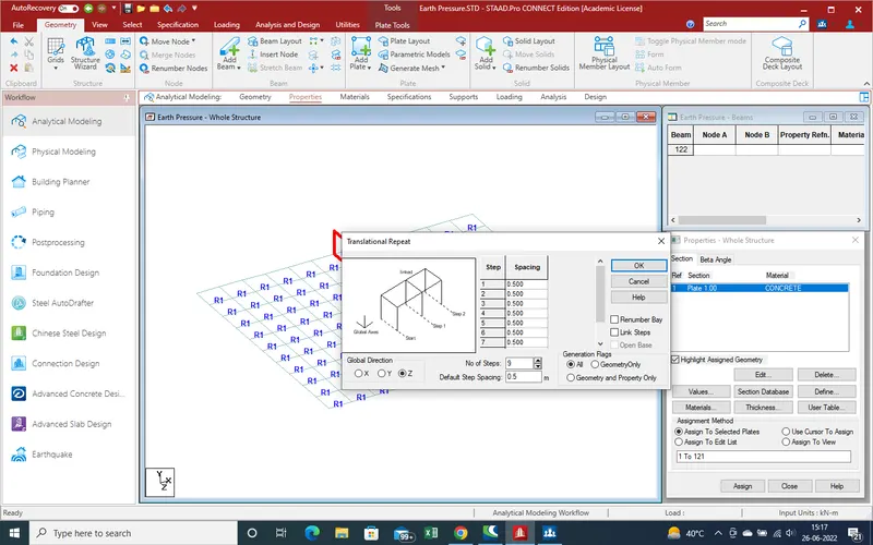
27.After traslation repeat command in Z-direction we get the result as
28.Same as use in y-direction ,here heigth is 10 m.
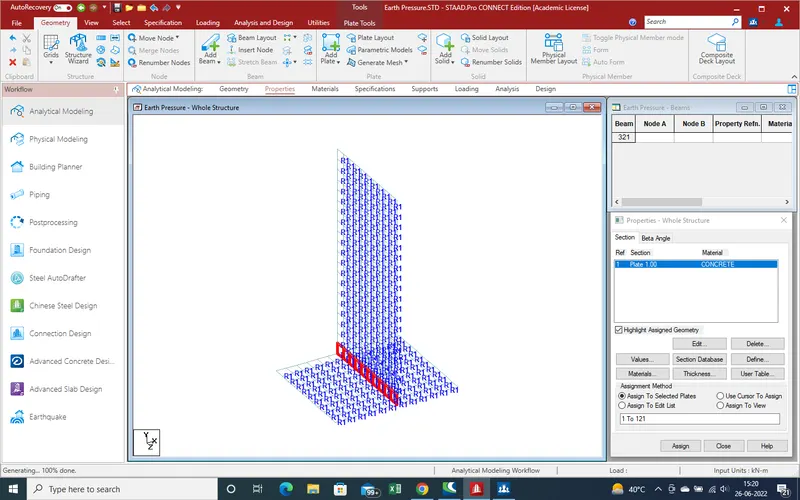
29.After compltion of modeling we get the results as given .
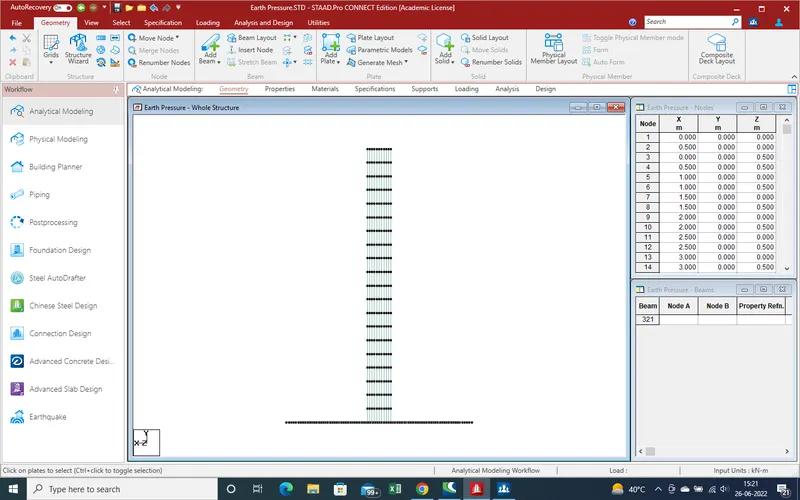
30.Now required the support reation. Here we use plate as foundation so we use plate mate reation .
as given below pic we use the plate mate reaction.
31.For support reation ,Select the plates on which we want the apply reation ,as showing in given pic select the plates for apply reation
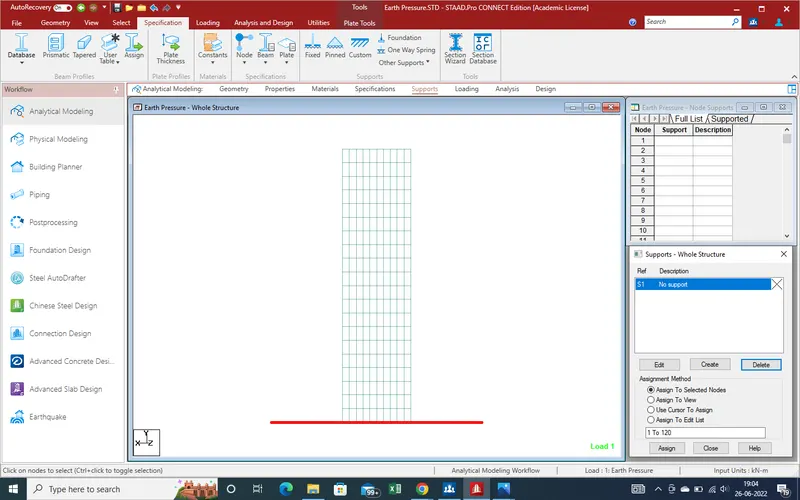
32.Select the Foundation,a new window has been open in main task as showing in given below pic.
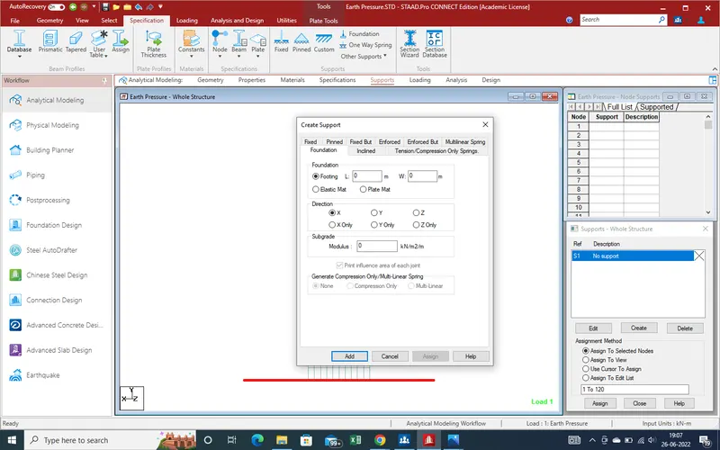
33.Select the foundation as "Plate Mat" and direction of loading are in Y-direction ,after subgrade moduls will be assume that 13000 kn/m2/m, due to soil moduls range is 12000 to 18000
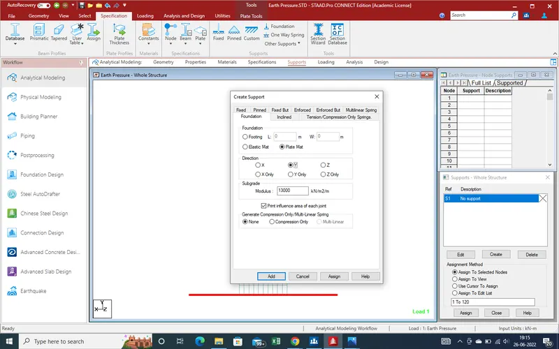
34.Now select the "Add" for add the support reaction, With Defined Data properties has been created ,now we just the need the select the plate for assign the support rection as given below pic.
35. as bottom plates select and after that we select the support reaction which one we define as s2 select and after thar click on "assign " .
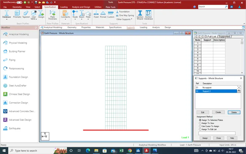
36.As we click in assign we get the note for confirmation that select we select can be procced , click on "yes" and we get the reaction on raft bottom as showing in given below pic.
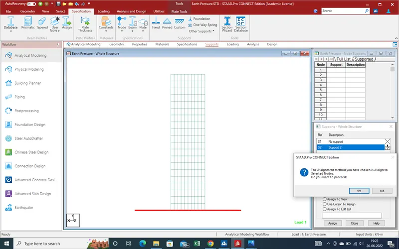
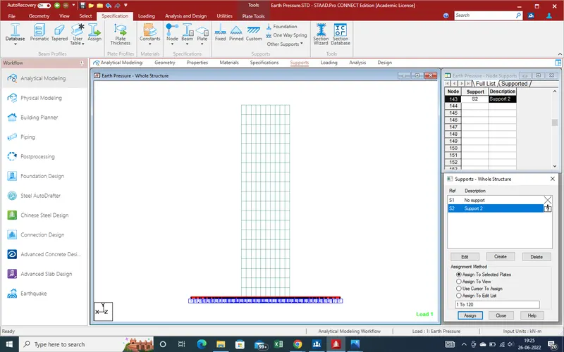
37. Now rather than loading all task has been complited, Now we check error in model like multi structure ,duplicate node , duplicate plate etc.
38.Go to "Utility", Check "Structure Tool " select "multiple Structure "
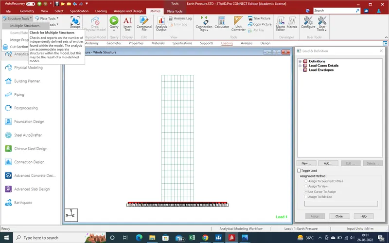
39.As we select "multiple structure "we get "structure 1" means whole model is one structure which is well connected
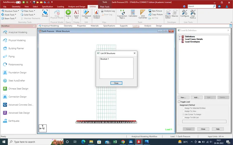
40.Now check the Duplicate node with 0.001 m tolerance and we get results as given below pic.
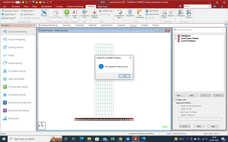
41.Same thing has been shown for Duplicate plate as shown pic.
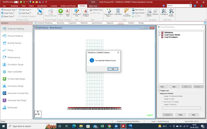
42.Now all task has been complited, now we can apply the earth pressure on abutment.
go to loading section "Select the "load Case Details" and Click on "Add" for Add load case as here earth pressure is our load type .
43. As we select the Add a new window has been open on main task window ,as showing in given below pic
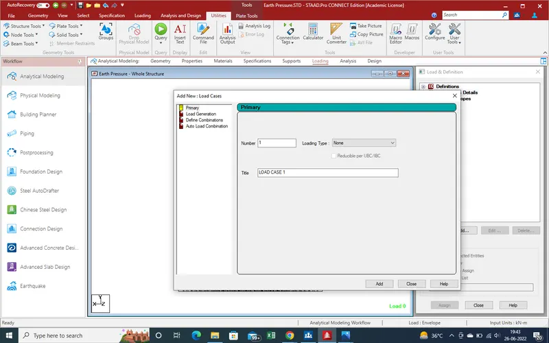
44.Take the name of Load case as "Earth Pressure " and Click on Add for Add load case as showing in given below pic
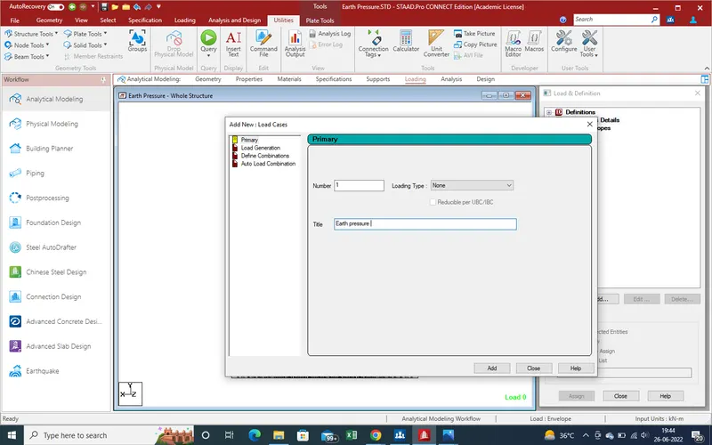
45.Now We Select the Earth Pressure in "load cases" and click on "Add" for Load which one act as Earth pressure
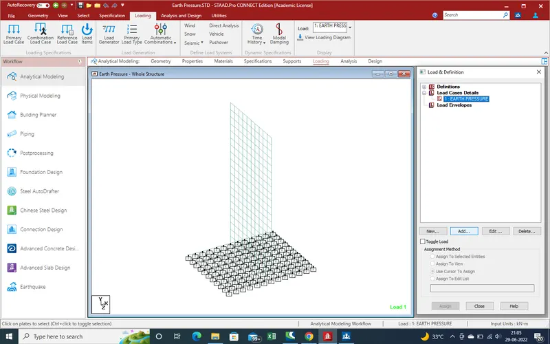
46.As we click on Add A new window of loading has been apear at Main Window as showing in Pic.
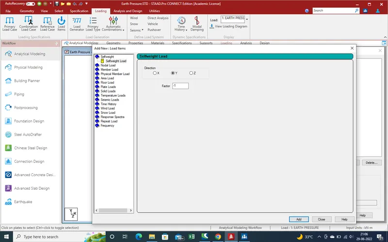
47.Here as we Model made in Plate section, then select the "Plate Load".But when select the Plate Load, here 6 types load acting option appear as showing in given below pic
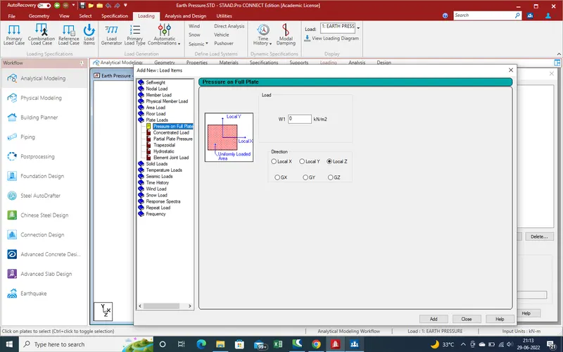
48.As Backfill Soil is acting as Hyrostatic load,which act incrimental load as per depth increase.
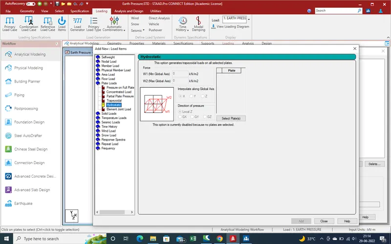
49.For Hyrostatic load we need the plates on which we want apply the soil pressure,but we know that as per given data depth of loading is 7 m from raft top, then select plates upto 7 m heigth.
50.As select the plates section existing window disapear and a new window open and plates selecting icon apear with a window as showing in given below pic.
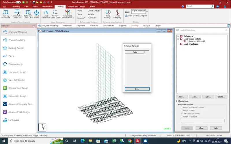
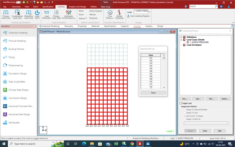
51.For Select upto 7m heigth plate change the direction of model as showing pic and select the plates upto 7 as showing
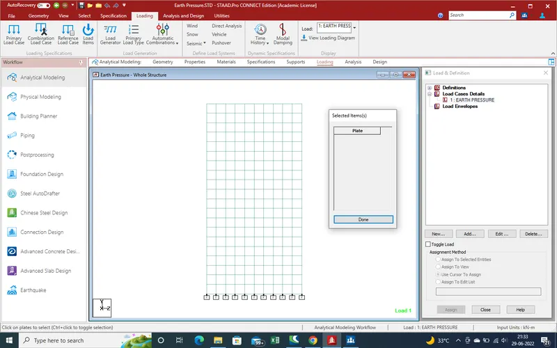
52.As we select plate,these plates added to side bar now click on done.
53.As we know that earth pressure=Earth pressure co efficient*Unit weight of soil * Height of Soil Filling.
but here we assume that Earth pressure Co efficient is 0.36 and Unit weight of soil is 18 Kn/m3 and H1=7m and H2 is zero.
So Active Earth Pressure at Raft top
=0.36*18*7
=45.36Kn/m3
and at top
=0.36*18*0
=0
so put the values w1 is max value is -45.36kn/m3.Put the value as negetive due to direction.
and w2 is 0.
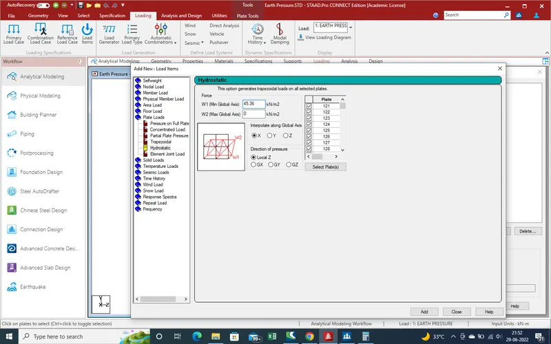
54.Now need the select the Direction of interpolation, which is y-Direction of Global and after that Direction of Pressure which is x-direction.
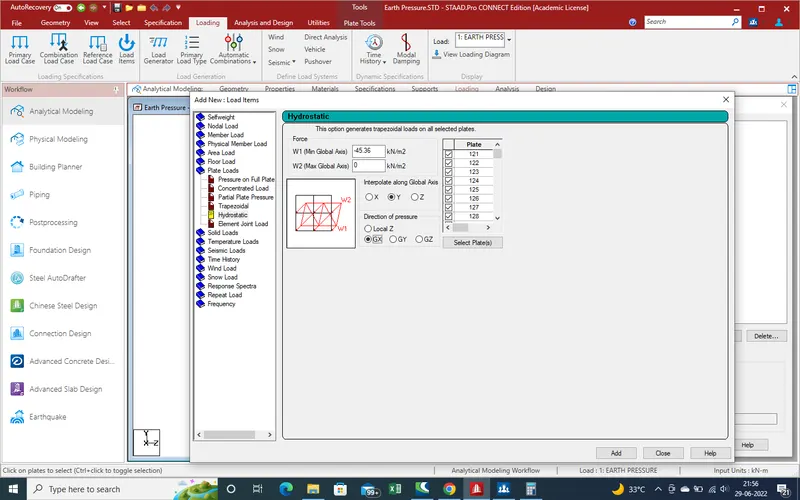
55.Click on "Add" for add the load case.As we click in side bar load cases created autometically.
56.In Down Stream heigth of Filling is 3m from raft height and second area is water logging area so
Active Earth pressure
at 3m height = 0.36(18-10)*3
=8.64kn/m3
here soil density is 18kn/m3 and water density is 10kn/m3 ,so soil dry density is (18-10) =8kn/m3.Select the plates where we want apply the load , anfter that
put the values in another Direction of applyed load.
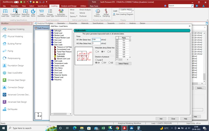
57.Click on Add for Add load case and close the window.
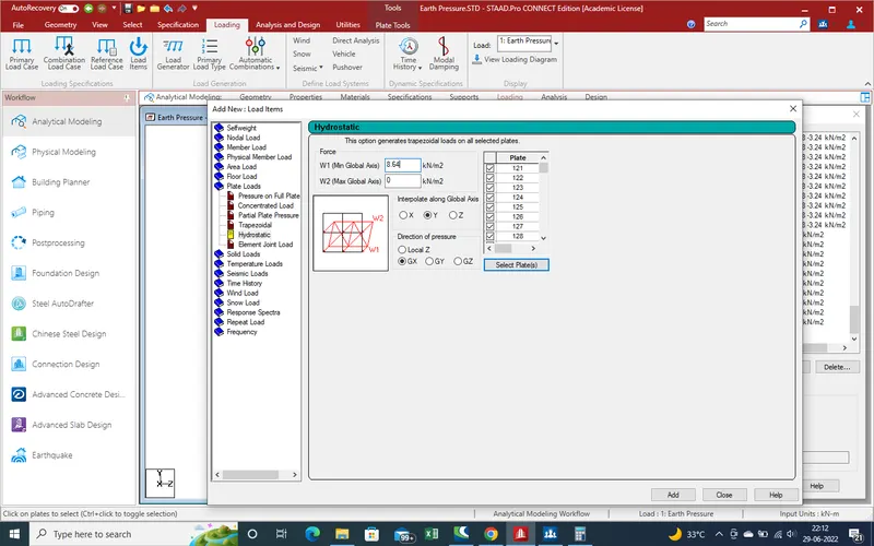
58.After add load cases ,close the window all load cases has been added in loading details .
59.As side view we can see the load which impact in abutment wall.
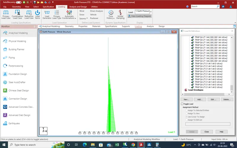
60.After Perform analysis ,Click on Run Analysis for find out the result
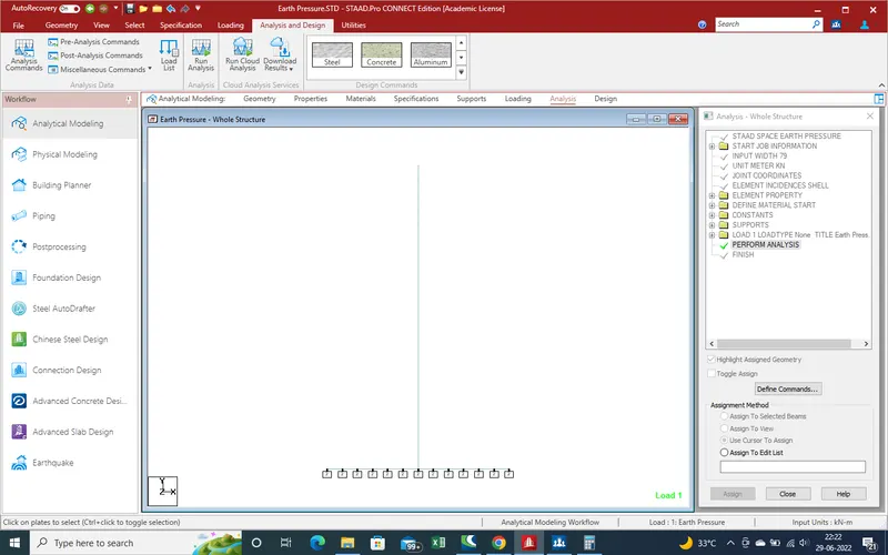
and we Get the results are such as
RESULTS :-
1.As we click on Run Analysis, Staad Pro run the file for analysis as showing pic.
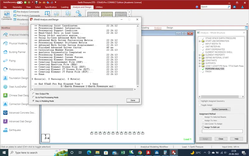
2.Here there is no error so we go for next step as "post processing mode" for analysis results
3.as select on "post processing mode a new window has been opened for select the load case, as here only Earth pressure so select the "earth pressure " and click on apply and then after on "ok".
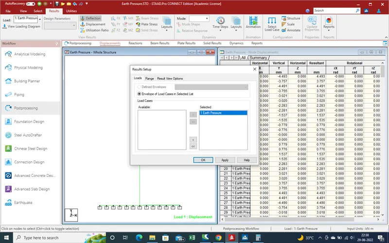
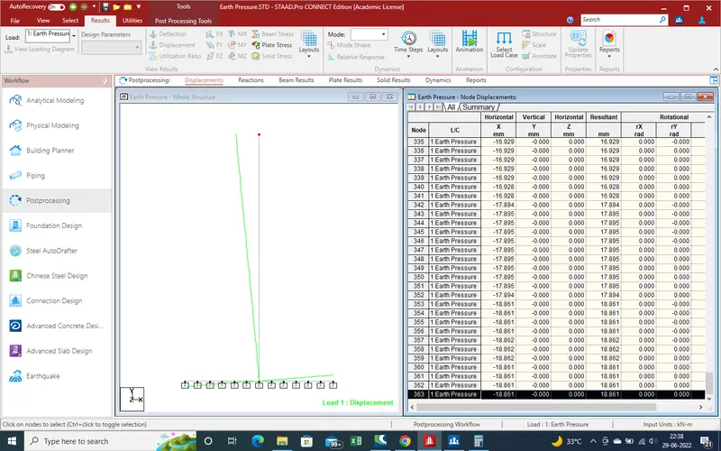
4.As given below pic we can see the node displacement results in high to low displacement of node.
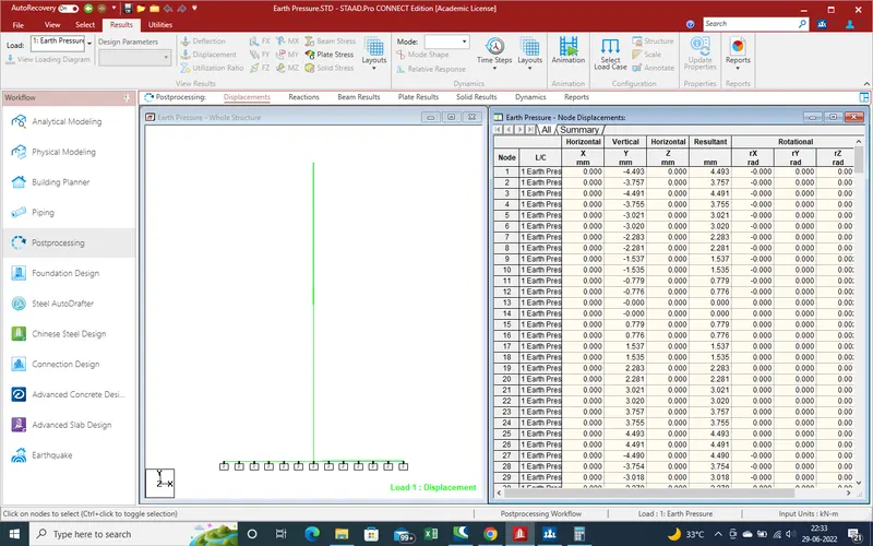
5.Displacement by earth pressure in x-Direction and negetive sign show the direction.
6.Now we find out the plates results like ,Principal major stress.
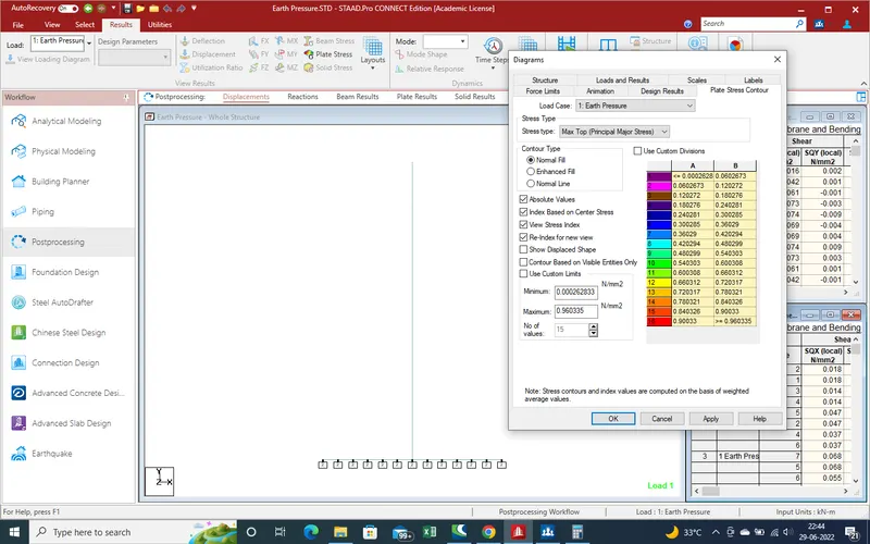
7.Click on Apply and get the results as .Here Different colour indicate the stress intensity
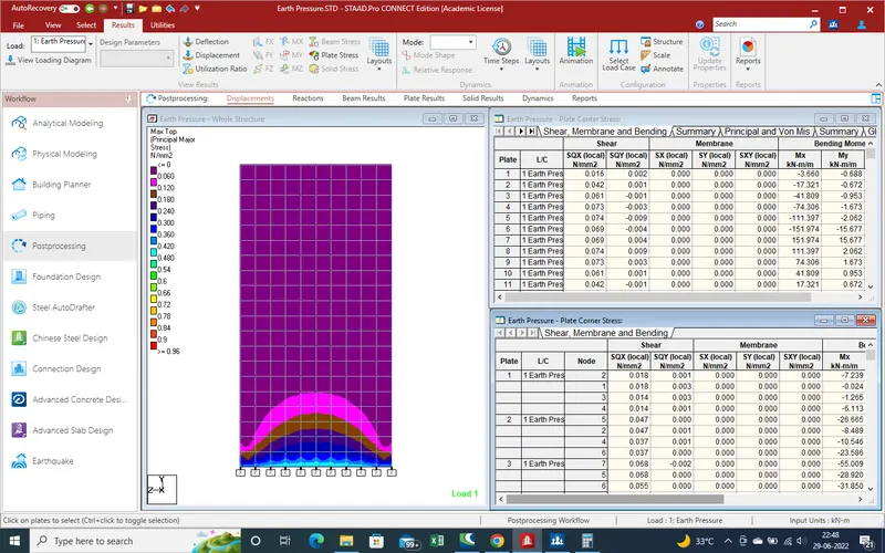
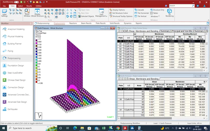
8.Globel moment
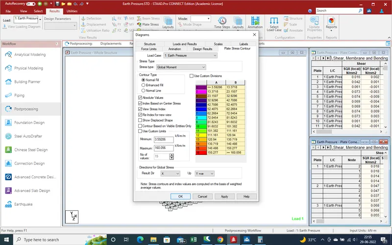
9.After apply the Globel moment we get the results with colour grapth so we can easly identify the min and max moment area with apropriate location .
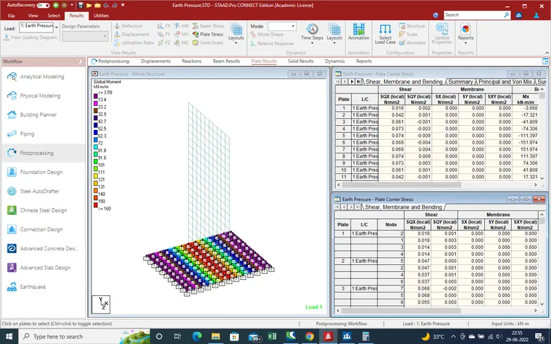
10.now with reports we genrate reports of model and find out all the nodes , plates ,loading and all results.
NOTE- now we here attached the file of model with results reports .