Week 2 Challenge
1.AIM AND INTRODUCTION :-
From week -02 We have to find out the Live load effects on Given Bridge Slab , like Stress, strain, Deflection,Moments Etc. by using Staad pro.
2.PROCEDURE:-
For find out the Live load effects on bridge, we need some data which are given such as
I girder type bridge
- Width of bridge - 7m
- Span of bridge - 24m
- Width of Main girder - 500mm
- Length of Main girder - 24m
- Height of Main girder - 1700mm
- Cross girder A.Width - 300 mm
B.Height - 1500 mm
- No if Cross Girder - 04
- Spacing of Main Girder - 1.900m
- Cantilever part - 1.000m
Now we use Staad Pro For Calculate the Desire Data From Given Data
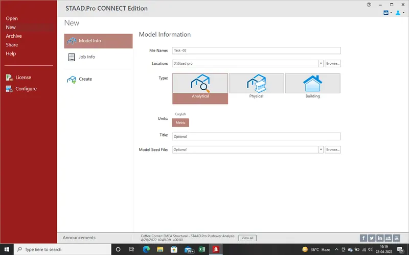
1.From Staad Pro, open new file as given pic we take the name of file "Task -02" and select the File loaction.After that Select the unit as "matric" and Click on "new "
2. Select the "new" then new window will get the Screeen as show in given pic.
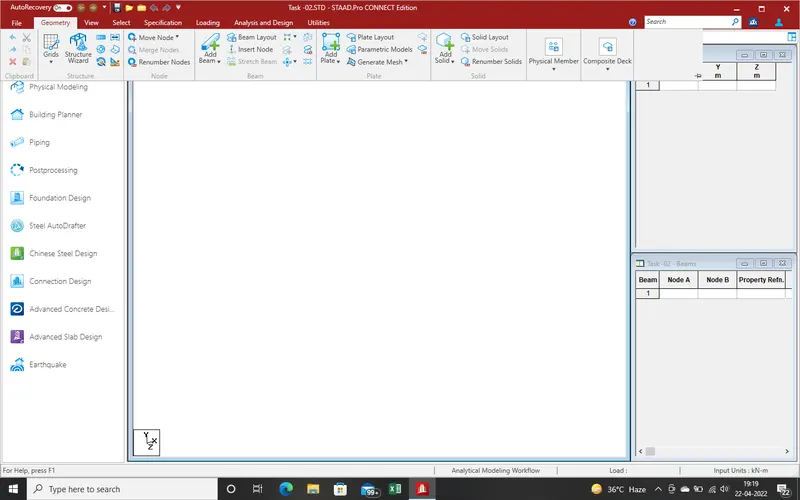
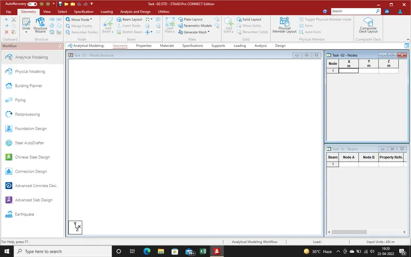
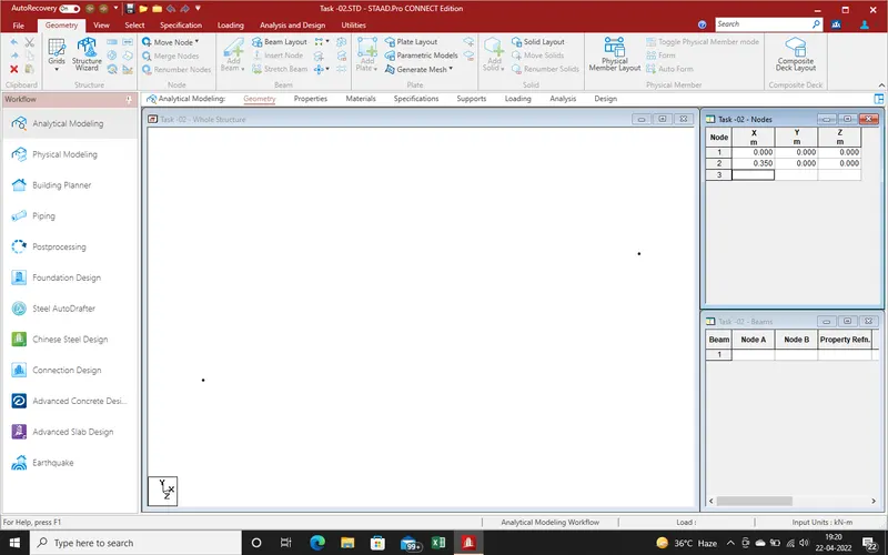
3.For draw the model put the values 0,0,0 for 1st node which is in "Geometry" Section due to Plates and Beam Shall be Connect with the help of nodes.
4.As we read the drawing carefully we found that span to span distance is 24m and distace from bearing centre to slab outer edge is 250 mm. so we need draw the bearing centre for cross girder and apply the support. we take 0,0,0 is slab outer edge and 0.250,0,0 is bearing location.now we get the shown pic result
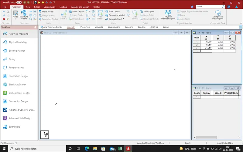
5.For next step we draw the next node at bearing loation at "D" in X-direction which is 24.250m from 0,0,0 we get the result As shown in given pic.
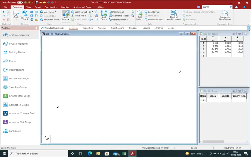
6.Now take the next step as outer edge of slab from bearing centre is same as "A" and distace from origin is 24.500m. Put the values of node and get the results as shown in given pic.
7. Need to connect the drawn node by use of beam. Select the "Add Beam" Command for draw the beam, which is showing in pic of staad pro in "geometry " section of Beam.
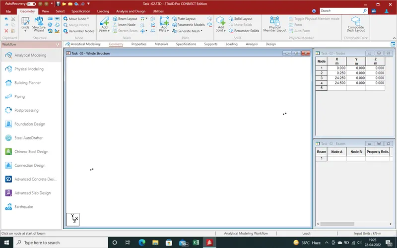
8.Click on "Add Beam" and connect the nodes as shown in Given beam and we get the result as shown in pic and we get the beam no as side task bar for prticular between nodes as beam 1 is in between from 1 to 2 and same as for remaining nodes and Beam.
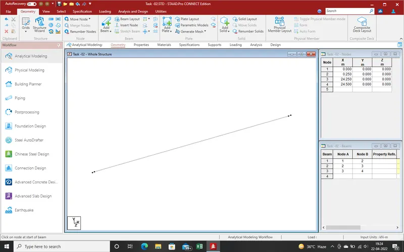
9.Now need the assign the properties of selected beam.for properties of Beam Click on "Properties". now in top bar we see that in Specification bar in 2nd no is "prismatic" for different shape beam for properties define.Need to seclect as pic in which Arrow is put.
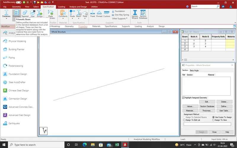
10.After selection of "prismatic" a new window will open such As shown in fig.Select the size for drawn beam as this is main girder which is as per given Data width is 0.500m and depth is 1.700m from slab bottom. then we put the values for rectangular section.After that need select the material as per drawing girder will cast by concrete,then select the material is "Concrete".
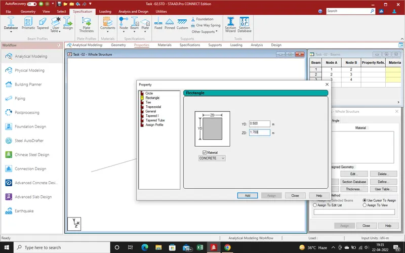
11.Click on "Add" and after that "Close". After the Close Widow the new tab Will apear at side bar with the new properties for Assign by different Different ways.
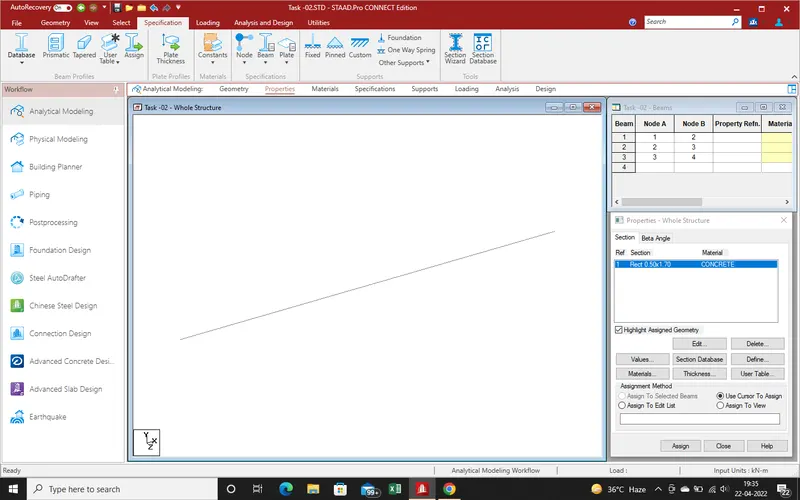
12.Select the properties which want to use and after that select the beam where want to apply and after that use the "Assign to selected Beam" command and click on Assign as show in given screenshot .
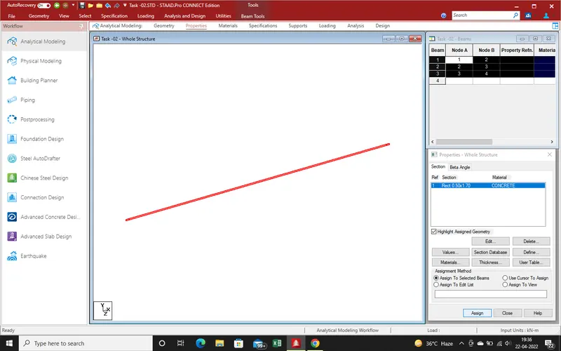
13.Need same Beam At prticular specified distance with same properties as per Given drawing.Use the Translation repeat Command.
13(A)There are 4 main girder span bridge then use same properties at prticular spacing .So use the translation repeat command for draw the beam with properties in minimum time .Select the Geometry no 3rd is use as "translation repeat " Click on it.
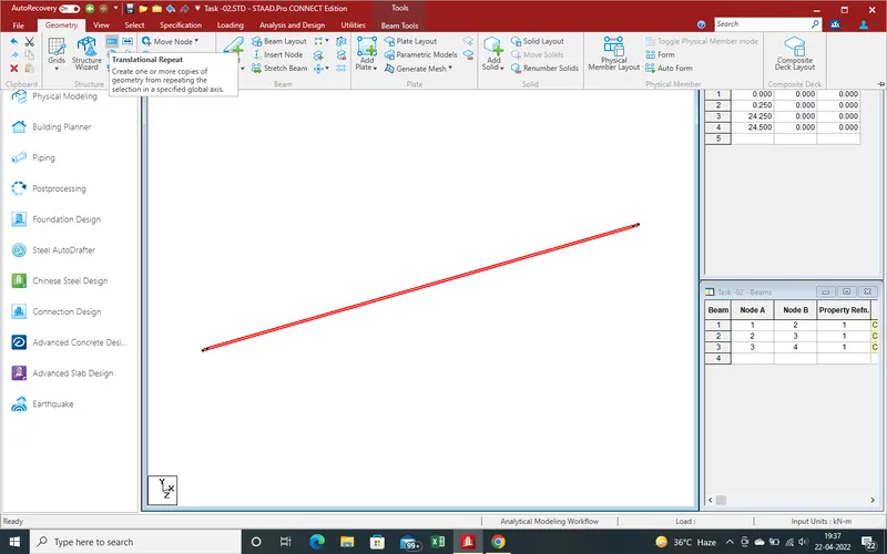
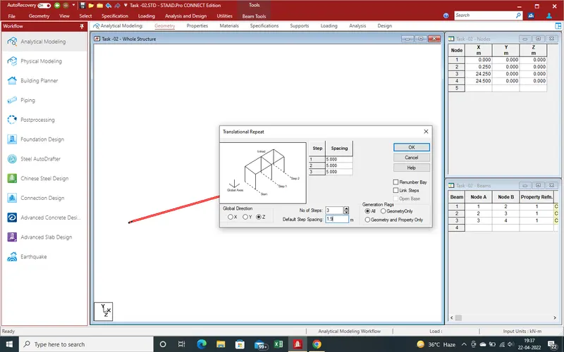
14.Get the new window at main window as showing below given pic.First of all need the direction of repeat command in Z-drection , then Select the Z-direction. Now nos of steps which are 3 beacuse of that total of girder are 4 and one of them already drawn, then remain 3 shall be done by using the putting the value 3.After that required centre to centre distance of main girder which is 1.9m and click on "ok" and get the result on next window.
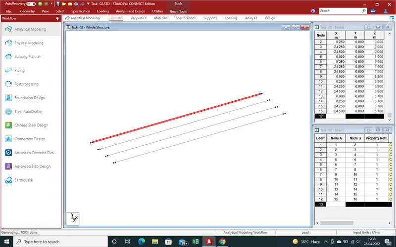
15.After click on "ok" window has been disapear and get the 4 main girder as shown on main window and inside bar get the nodes nos and second window for beam no with properties references.
16. Draw the End Intermediate diaphragm same as Main Girder by use the Beam Command and draw diaphragm at bearing support loaction as shown in pic as per given Data
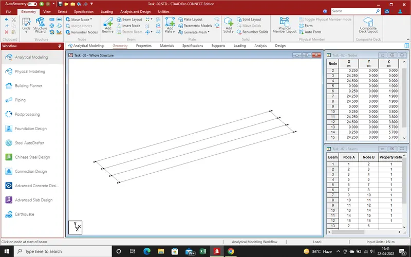
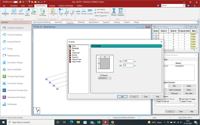
17.Now Apply Properties of end Diagraph,again go for Specification in Prismatic command after that shape as Recatangular section as open in new tab as pervious ,now put the width and depth values.After Click on "ok" and then "Close"
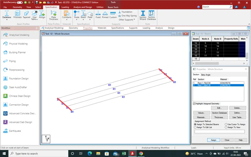
18.Now We Assign Properties of End Diagraph,Select the properties Which one recent we define for Diagraph and Select end diagraph and Assign
19.For Entermediat Cross Diagraph we Get that Properties are same as end diagraph at specified distance so we again we can use "translation repeat " command for draw with properties.
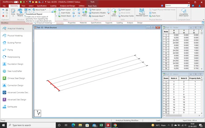
20. After Selection of Translation Repeat Command We get the new window on main task bar.first of all need the direction of reapt command,after that no of step as here 2 entermediate diagraph so we put the set 02 and spacing in drawing is 08m put the values and Click on "ok"
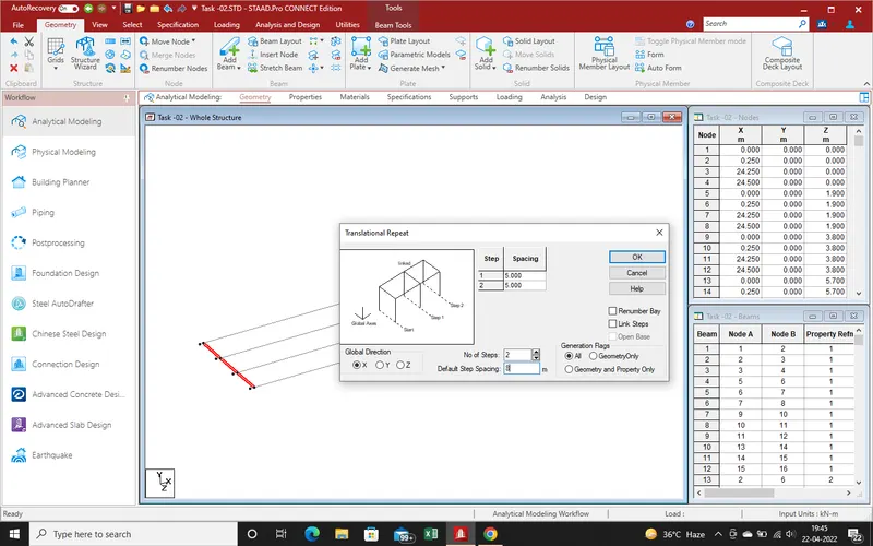
21.Now we get the diagraph with Properties same as pervious Diagraph.
22.Now we need draw the plates on Girder as slab in small parts.
23.For Draw the Beam we Need 4nodes for Square Plate.We use the Translation Command For Draw the node.For select the node Go For "Select" Sectionand Senect the node Cruser and select the node for copy node for draw the plate.
24.Now Select the Translation Command And Select the z-direction for node as 0.475 m from select node as shown in pic
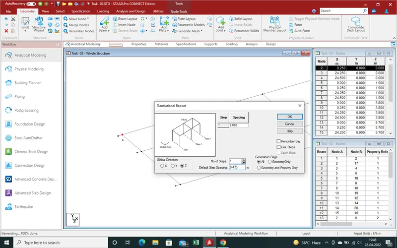
25. same process apply for next node at support end
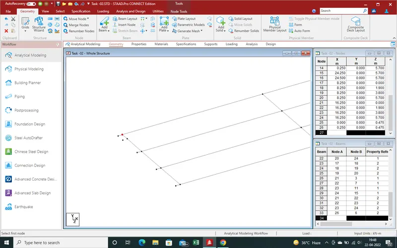
26.Now we have 4 node for Draw the Plate.in Geometry Section we select the Command of plates and connect all 4 node and get the Plate as per Given Pic
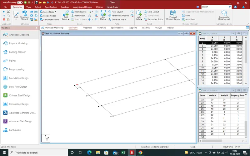
27.Now need to define the properties of plate.Go for "Specifiation" section and Click on Plate thickness. again an new window has been open.as per Given the Data slab is uniform of 0.200m thickness then put the values the 0.200 and click on "ok" and Close
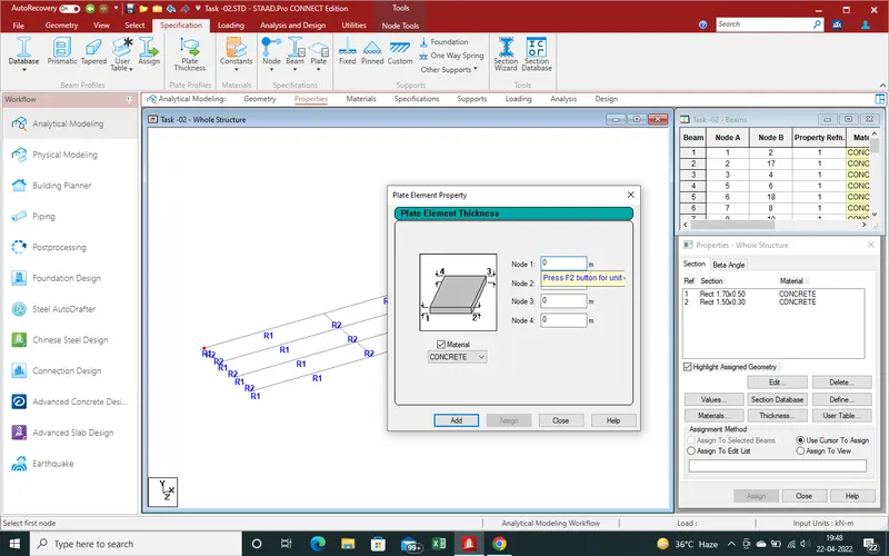
28.In Side window specfied properties shown.select the plate properties and select the plate where we want apply Properties and assign as below given pic
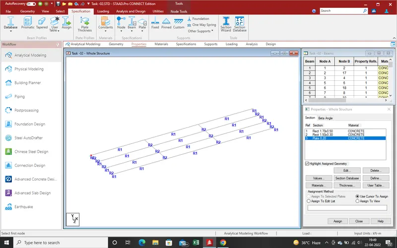
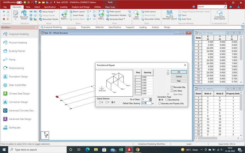
29.this plate can be same for longitudinal in z-direction so again use the translation repeat command.for select the plate first need select section and select curser for plates. select the plate,and go geometry section and select the translation repeat command.direction is z-direction,no of step is 11 and spacing is 0.475 and click on ok as given pic
30.Results are such as
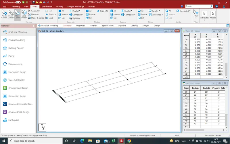
31.Same plate shall be plotes use of Translation repeat command on other end as shown pic
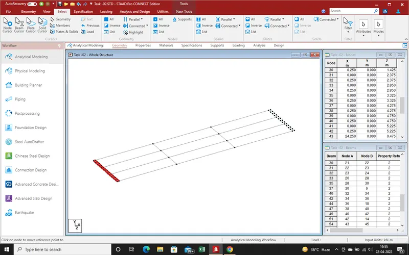
32.Now need for Slab in cantilever section plates,use node plot as per pervious command but there is difference that it will in reverse direction so use the negetive sign(-).
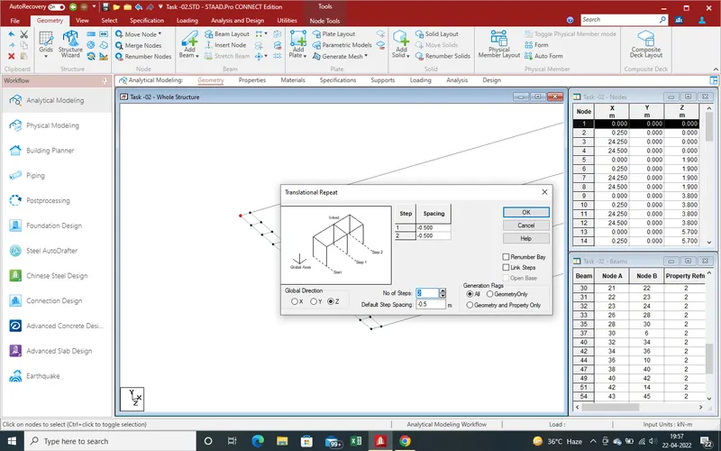
33.we get the follow result as below pic
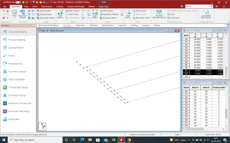
34.For Plate Draw need atleast 4 node point so in X-direction again need draw node.again use the translation repeat command as pervious use. and spacing in X-direction is 0.250m as shown in below fig
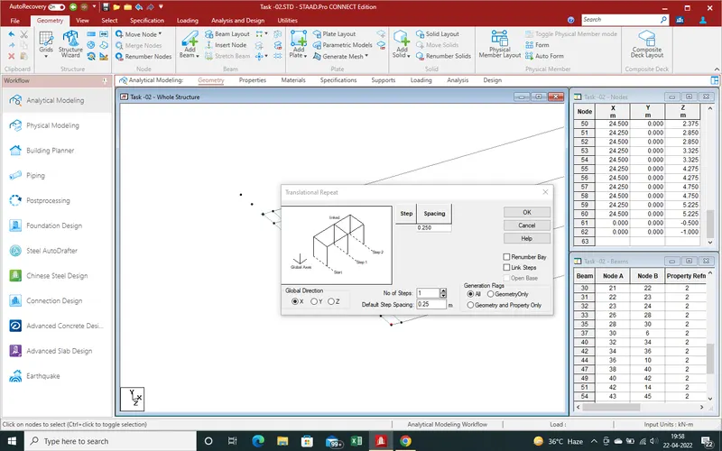
35.As use of traslation repeat command we get the below fig for draw the plate.
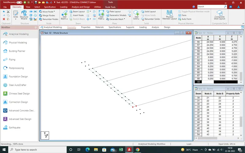
36. In geometry command go in "add plate" command and Draw the plate for the cantilever section as showing in fig in both side.
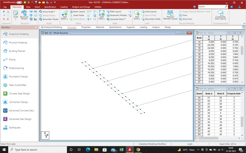
37.Now select the plates which one recently drawn, for copy paste in A2 Side by use of traslation repat command as showing in below fig.
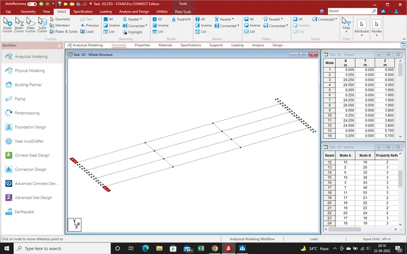
38.For Create the plate in X-direction with different spacing,need the copy paste the pervious node.go in select section and select the node after that select together all nodes which are require for plate node as showing in below fig.
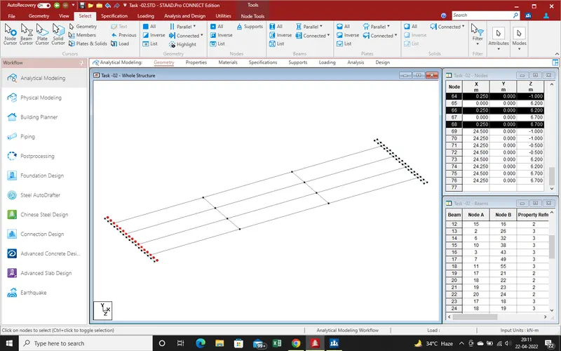
39.By use the translation repeat command and get the below fig results.
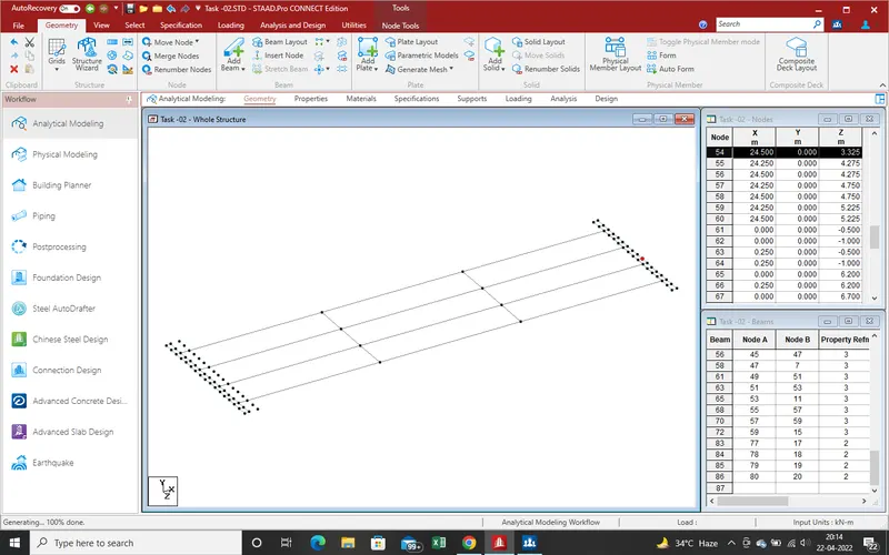
40.In Between the girder Area spacing and size of plate are same so there is no need draw sperate plate,use of traslation repeat command as in Direction is Z-direction,no of step are 11,and spacing use as 0.475m.
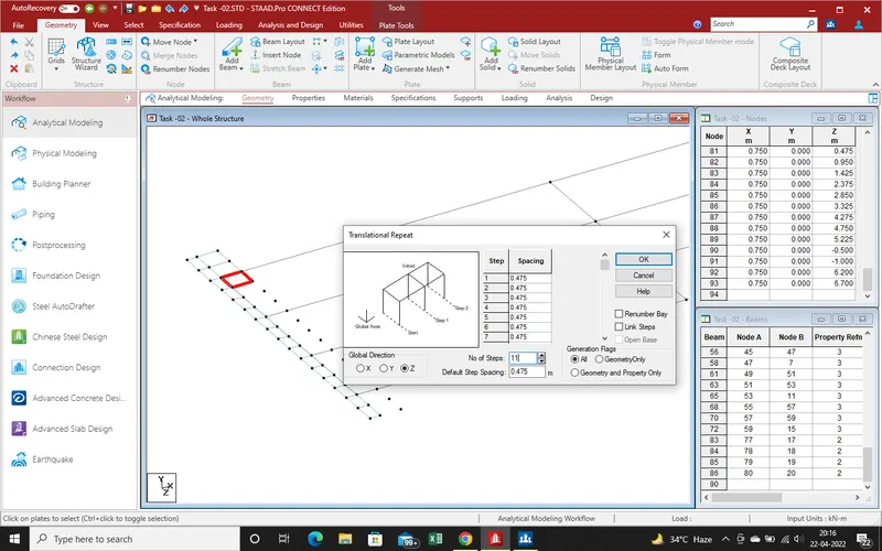
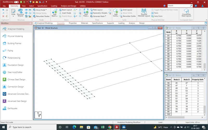
41.and cantilever section we draw 3 plate manually draw as showing in fig.Get the plate all row in Z-dirction.
42.Again go to "select" section for selection of "plate " for select of plate for traslation repeat command, after view section for top view for select all plate in Z-direction easly and select all plate for traslation in X-direction.Open traslation repeat command after that Direction is X-direction,no of step calculate by length devide by spacing, Get the 47 step and spacing is 0.5m. Put the value as showing in Fig. And Click on "ok".
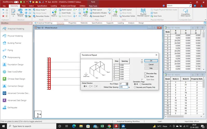
43.We get the plates in Whole Area as showing in Fig.
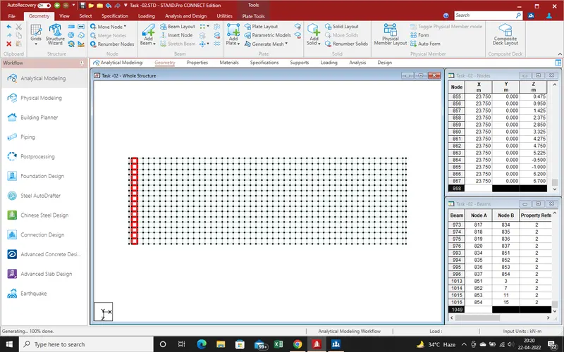
44.Now Next Step is Provide the Support to Structure which we Draw. Select the Node Command And Select the position of Support as per Given Drawing and Data.As bridge are pinned Suppored Structure. Select the pinned Support as Shown in fig.which one will add in side window.
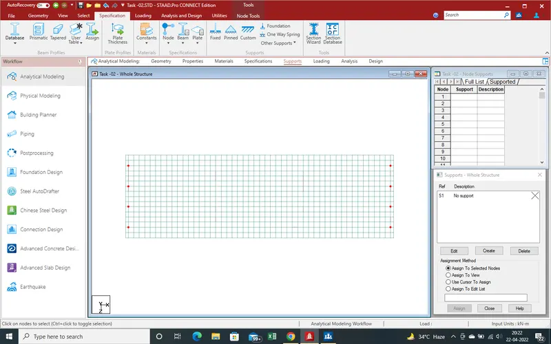
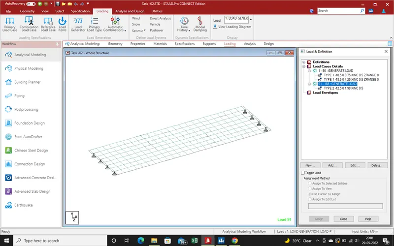
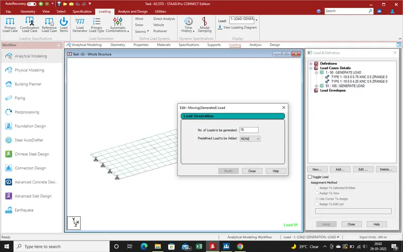
45.Use As "Assign to selected Nodes" and assign as showing in Fig.
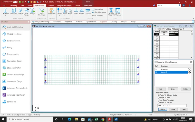
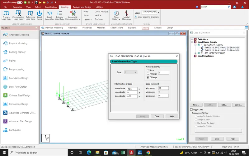
46.Now we get the whole Structure as showing in Fig as below.Now we check the error as duplicate node,beam and many other error which make the wrong results.
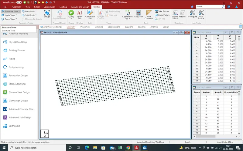
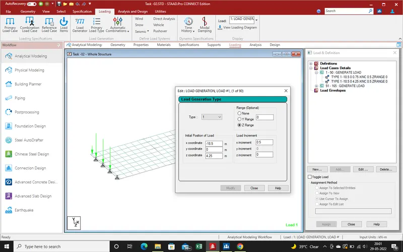
47.Go in "Utilites" section and after that "Structure Tool" first of All Check the "multiple Structure"for analysis can be accommodate spetate structure.
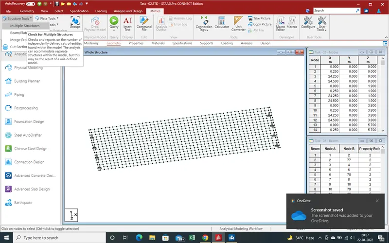
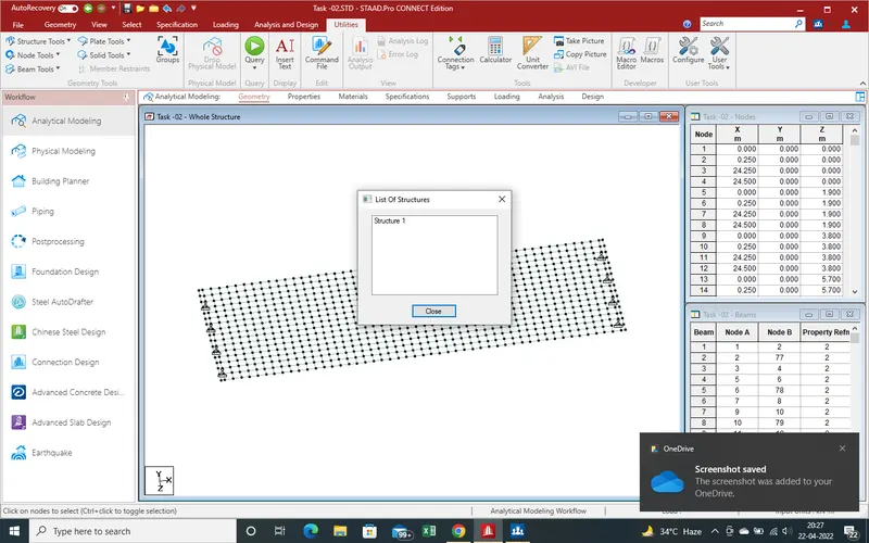
48.We get the Single Structure which means we Create Single Structure for analysis.
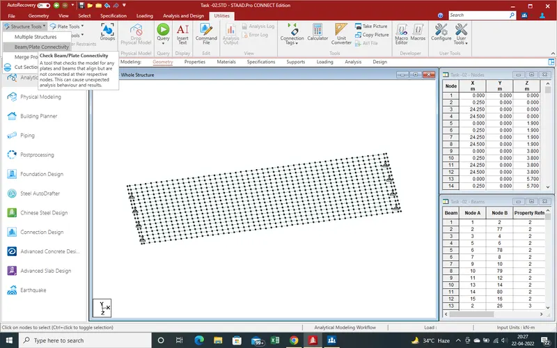
49.Now check the plates and beam connectivity by using the "Beam/Plate Connectivity " Command in Structure tool.
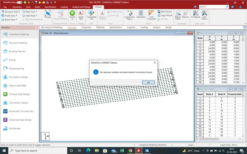
50.Again we Get that there is no improper member and plate element connection in this Structure.
51.Now Node tool command will check for node related error in structure just like duplicate node,overlap node types error.
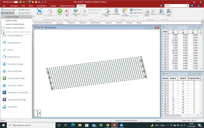
52.For Remove Duplicate Node We use spacing between two node for tolerance is 0.001m and select the "ok".
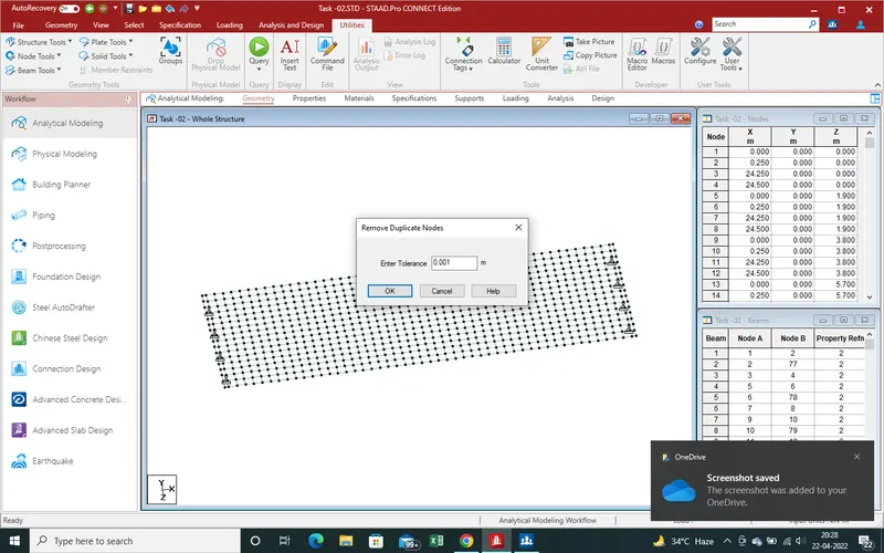
53.Now we find the Duplicate Beam for remove the error.just like overlap beam ,duplicate beam,zero length beam.
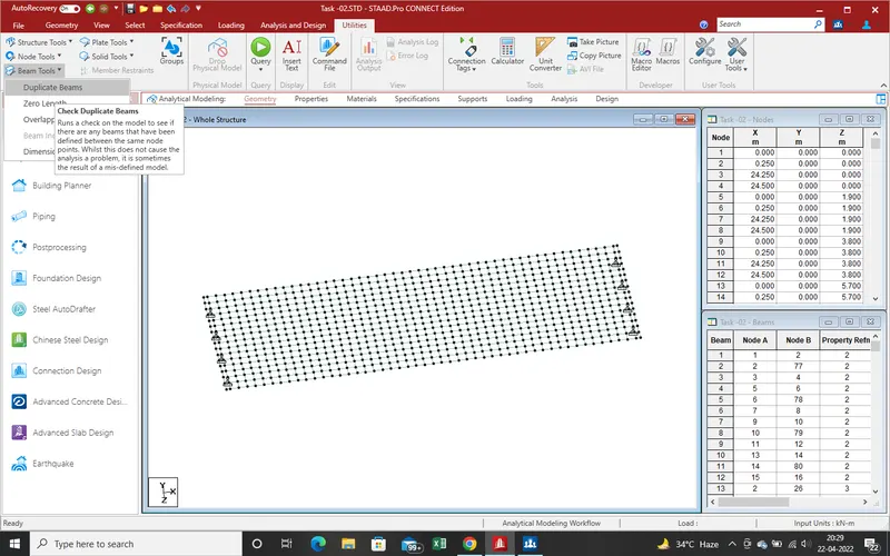
54.In Beam Tool ,first find the Duplicate beam and click on "Duplicate beam".
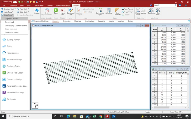
55.there is no duplicate beam.then its ok.
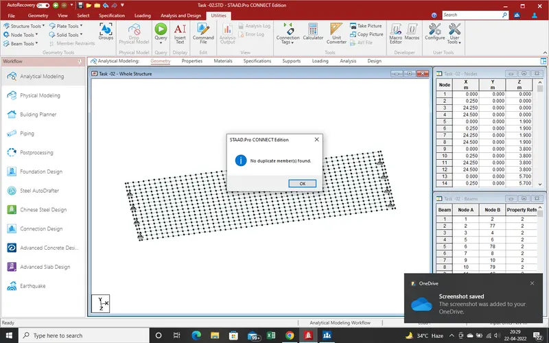
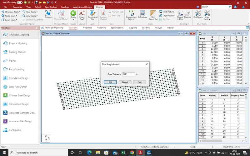
56.Now Find out zero length Beam and put the tolerance value as 1mm and click on ok.
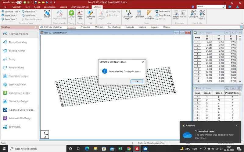
57.Again there is no beam if zero length beam in this structure.
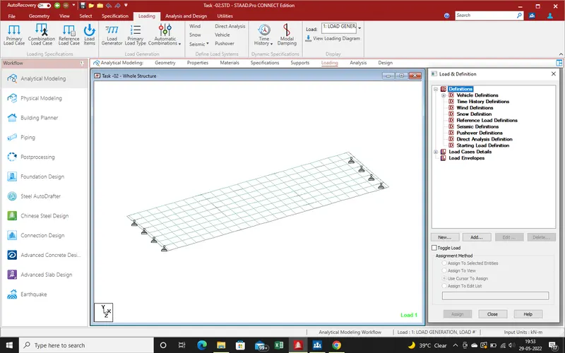
58.As all terms and condition has been pass by structre no we apply the loading as per IRC -06 2017 .For loading go to "Defination Section "and Select the no1."Vechile Defination" as showing in below given fig.
59.Now In next step go to "vechile Defination " and Click on "New" a new Window has been open at Main window
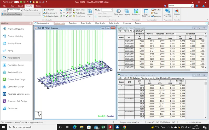
Select the type Vechile as there "1" as consider for A class loading.As per IRC-06 Fig-2 (Clause 204.1).Width as per IRC is 1.8 then put the value 1.8m.After that put the load in Kn term and Distance in M,as IRC
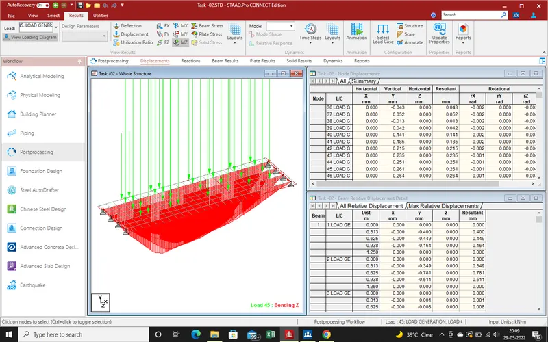
1.27Kn -
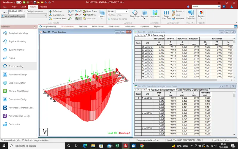
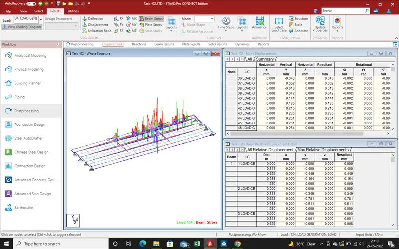
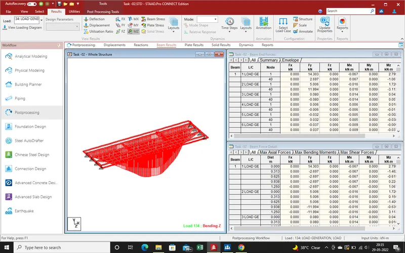
2.27Kn 1.1M
3.114Kn 3.2M
4.114Kn 1.2M
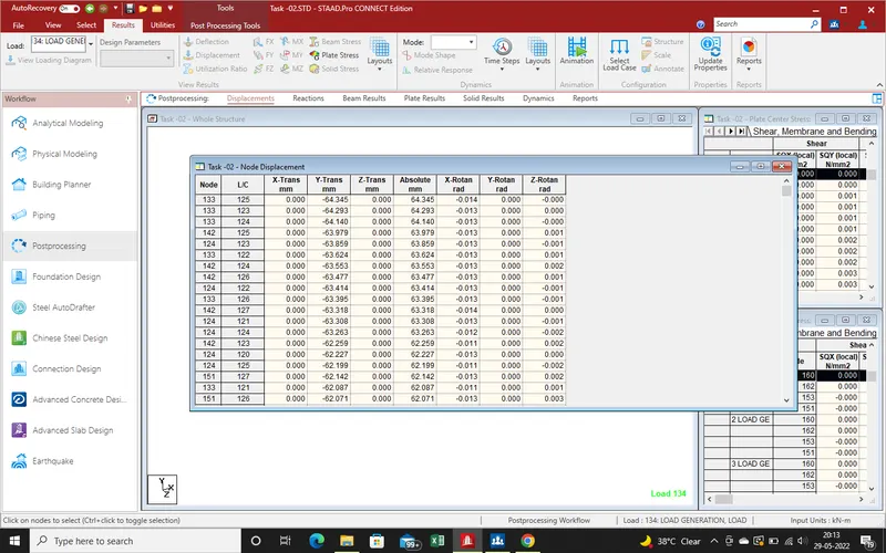
5.68Kn 1.2M
6.68Kn 4.3M
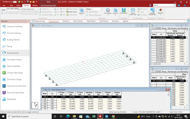
7.68Kn 3M
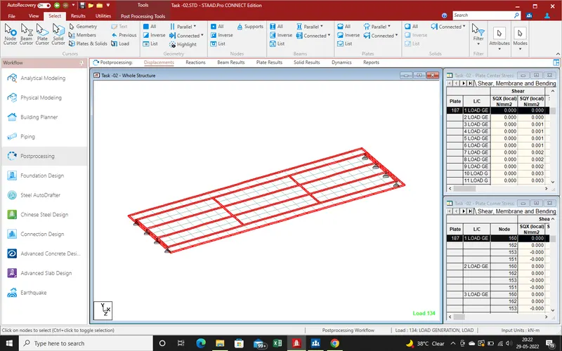
8.68Kn 3M
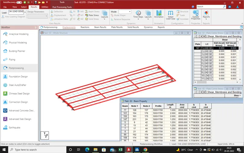
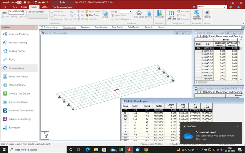
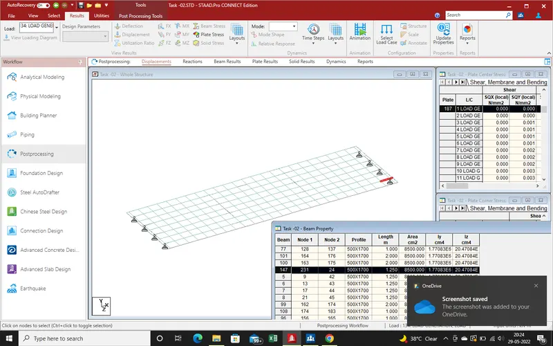
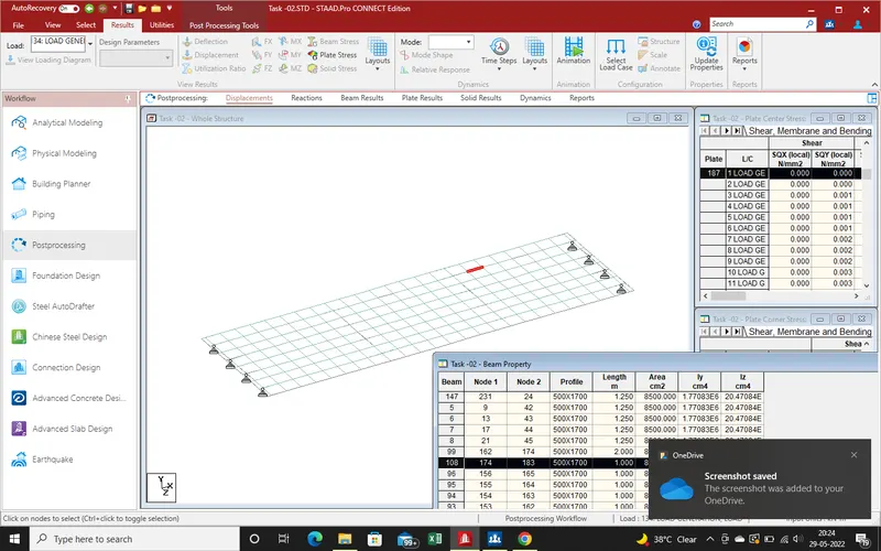
Click "ok"
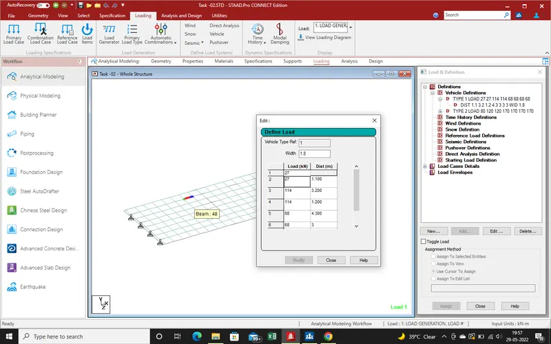
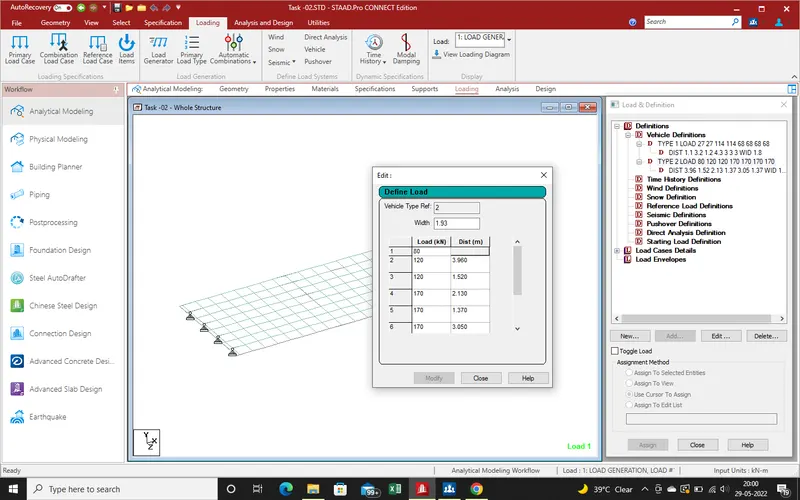
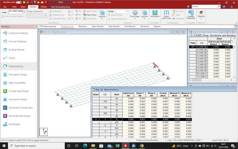
60.Now Again For 70R (Wheeled Loading) loading same use the IRC-06 Fig-01 (Clause 204.1), First of All select the "Vechile Type" as "2" and Width consider as 1.93m due to we consider L-Type Tyre Loading.Now put the loading with specified Distance as per IRC Which Are such
1.80KN -
2.120KN 3.960M
3.120KN 1.520M
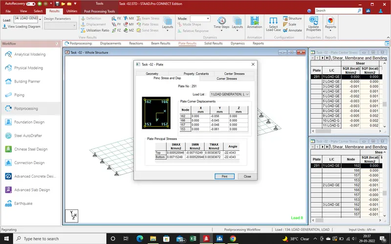
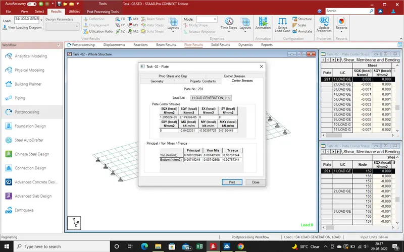
4.170KN 2.130M
5.170KN 1.370M
6.170KN 3.050M
7.170KN 1.370M
and Click "ok"
61.Now Load Cases Details
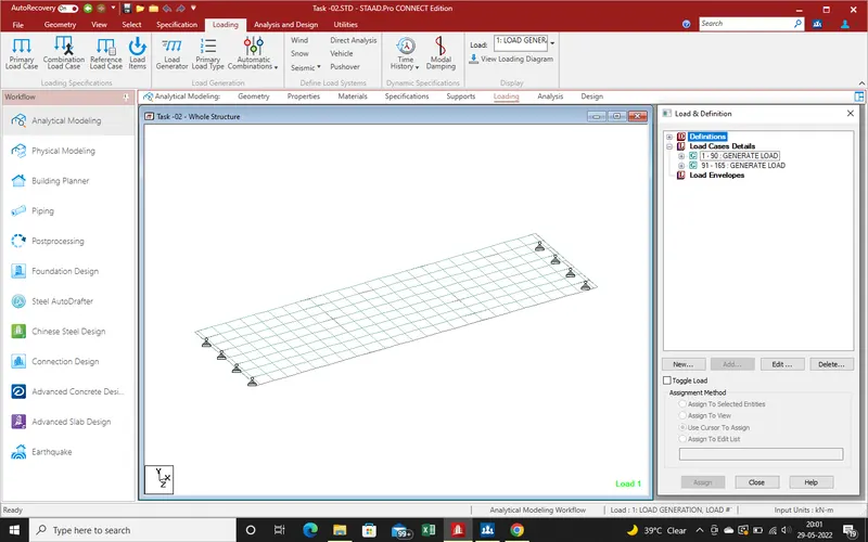
Select "New" A new Window will open in main Window,there is need no. of Load to be generated,As there is span is 24 meter and length of A class loading 18.800 m, and loading intervel let be 0.5 so approximatly 87 nos so use as 90 nos of Case as shown on Fig.
62.For 70R (wheeled load) slab is also 24 m and length of vechile is 15.530 and interval of loading is 0.5 then total no of load is 80 so we there is use only 75 nos and click on "ok" as showing in Fig.
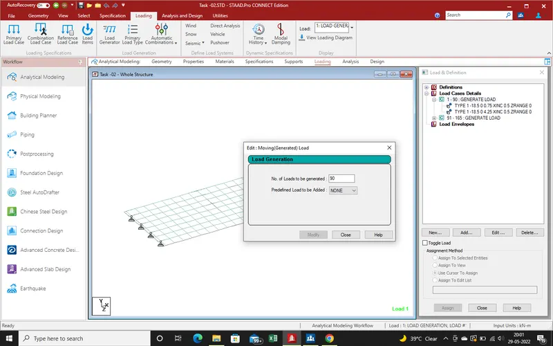
63.Now Select 1-90 Load and click on "New " a new window will open in main window Again Slect the "Load Generation Type" there need Type select which load will use as we Select first A-Class loading which is "1" then select "1". after that Initial Position of load shall be providing by coordinate values.In X-direction put the first value is "-18.5" due to length of vechile is 18.800m,Y-directiion value is 0 and Z-Direction value is 0.75.After that select the range as here select Z-Range.Load applied interval select as 0.5m in X-direction and Click on "ok"
64.As here Bridge Carriage way width is 7M,So as per IRC-06 Code Bridge is 2 lane Bridge and For A-class loading in 2 lane Bridge Need 2 A-class loading.As per IRC code same Process At Specified distance Shall be follow as showing in below Pic.
65.For 2 lane Bridge 2 type loading shall be Applied as per IRC-06 2017, Only one lane of 70R loading allowed.As per Loading 2 type loading is 70R loading then Select 91-165 GENERATE LOAD Select and After that Select "New" New window again Open Same Processed As Pervious A-class Loading as per IRC Loading.
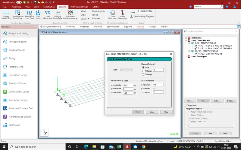
66.Now final Step remain.Go to "Analysis" Select Analysis Commands and select "Perform analysis" and "add" and close the window.
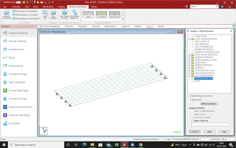
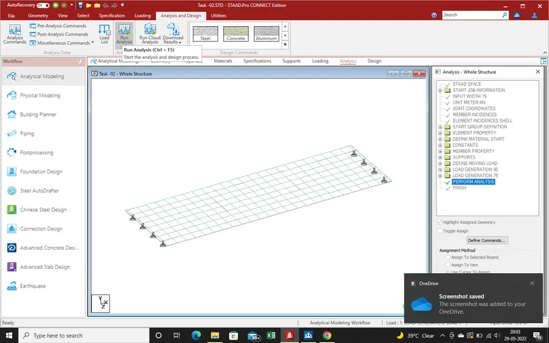
67.After that Click on "Run Analysis" and Showing in Below fig.
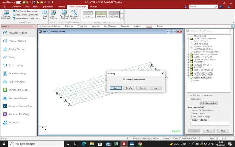
68.After Select the Run Analysis A new Window Has been open in And Select "Save" .
69.As we Select "Save" Analysis Has been Started As Given below Pic.there is "no error" means project has been successfuly Done.For Get the Results Need "Go to Postprossessing Mode".
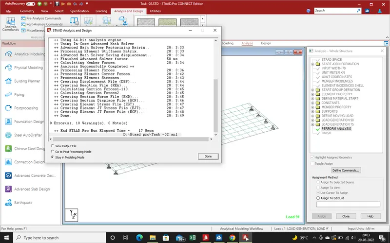
70.Now In Result Section We can See Applyied Loading Diagram and Load.As per Load Here we can Get Deflection, Displacement,Shear Force in X,Y And Z Direction same As Moment in X,Y and Z -Direction which Some Sample can be See here below Pic.
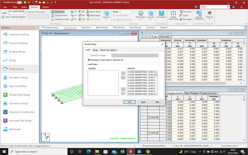
71.For Deflection, load-01 results
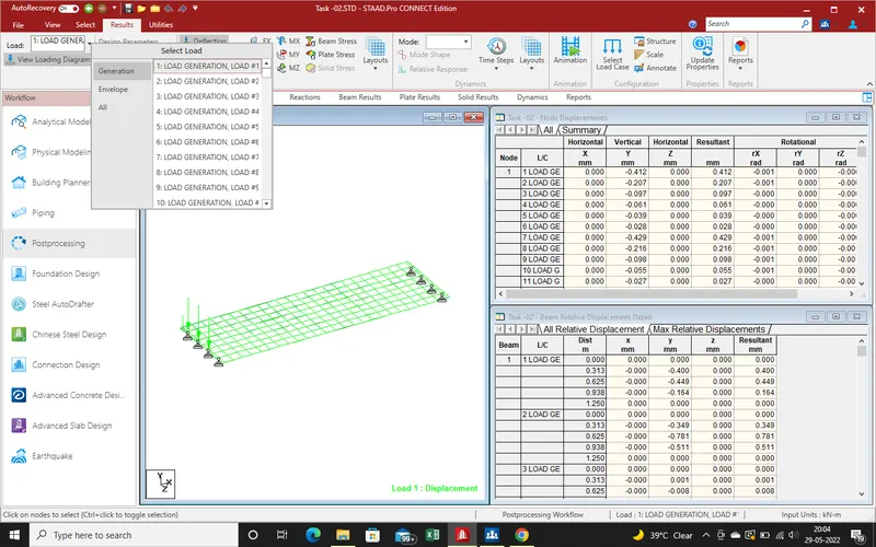
72.Displacement at Load -01
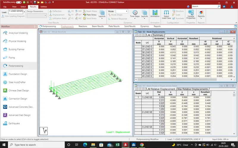
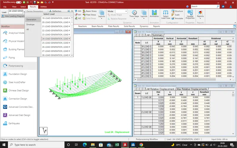
73.Load-24,Displacement
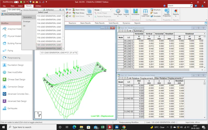
74.Load -121,Displacement Result
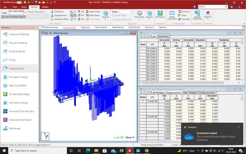
75.Shear Force at Load-20.
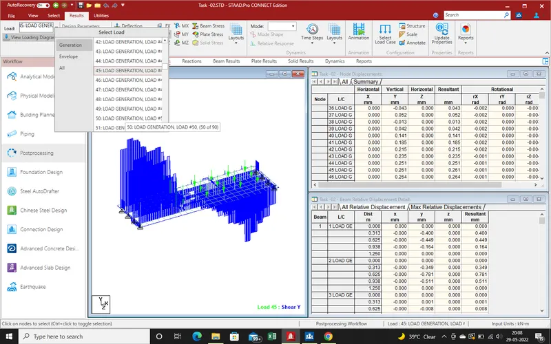
76.Shear Force in Y-Direction at Load-45
77.Moment about x-direction at load-45
78.Bending Moment about z-direction at Load 45
79.Beam Stress at Load-34.
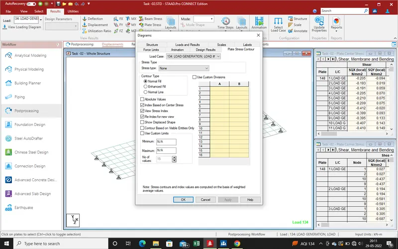
80.For Get The Report of Beam Stress and Moment,Select Beam after that Select Report Section.
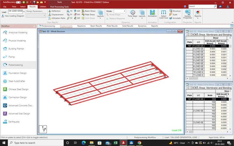
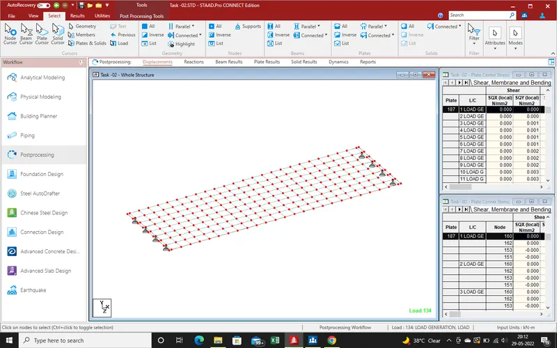
81.For Node Stress and Displacement Select Node And Report Section as Showing in below Pic.
82.Node Displacement Select "Absolute Dispacement " and After that Select List From High to Low and Click on "ok"
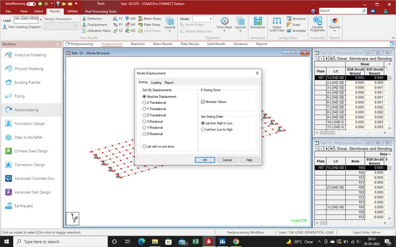
83.Get the Results as Node133 Has Max dispalcement as 64.345mm,same as below fig showing in high to low displacement.
84.Same As we can also see the selecting after Node the select the node line. as show in given below Fig.
85.Again Select Beam Curser and Select all Beam for find out the Displacement in Beam.
86.here node details(Beam Properties Section) like Dimension,Area, Moment of Inertia etc as show in Given Pic.
87.Beam End Force
88.Section Displacement
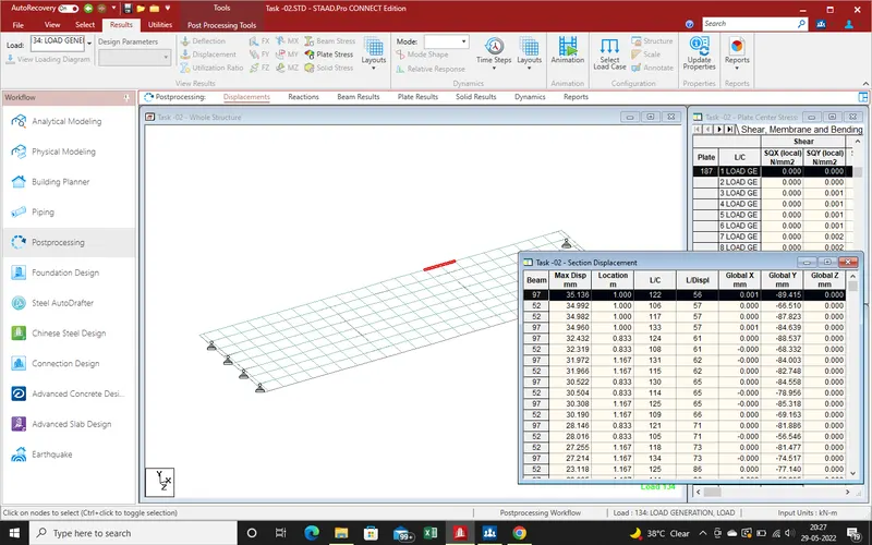
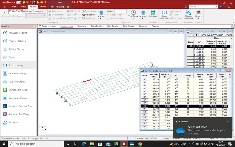
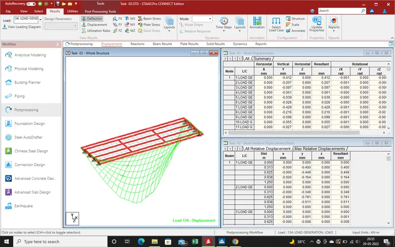
89.Whole Structure,reaction
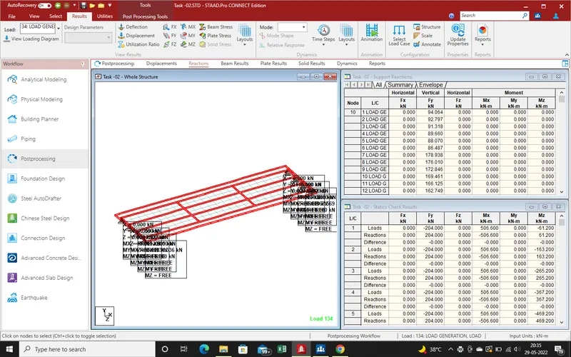
90.Whole Structure -Beam Results
91.Plates Results
92.Plate Stress