Week 3 Challenge
Aim & Introduction :-
To find out the Displacement ,Shear Force ,Bending Moment and Etc With the help of Staad Pro Due to Live Load According to IRS Railway Loads on Given Bridge Data.
Procedure :-
For Find out the Displacement,Shear Force,Bending Moment,torque and etc Due to IRS Live load need data which are given such as
Given Data :-
1.Total Width of Slab-27.575m
2.Span of Bridge -25m
3.Girder -I Girder (Dimension not Given)
4.Slab thickness -Not given
5.No of Girder -08
6.Spacing - Assumed
7.End Diaphragm - Assumed
From Given Data we Find Out the results of Displacement,Shear Force and Bending Moments etc. Now open the Staad Pro and follow the procedure as given steps
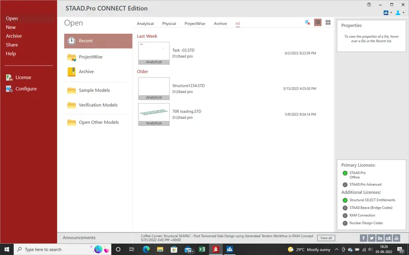
1.Open the Staad pro and Click on "new" and Show in given below Pic.
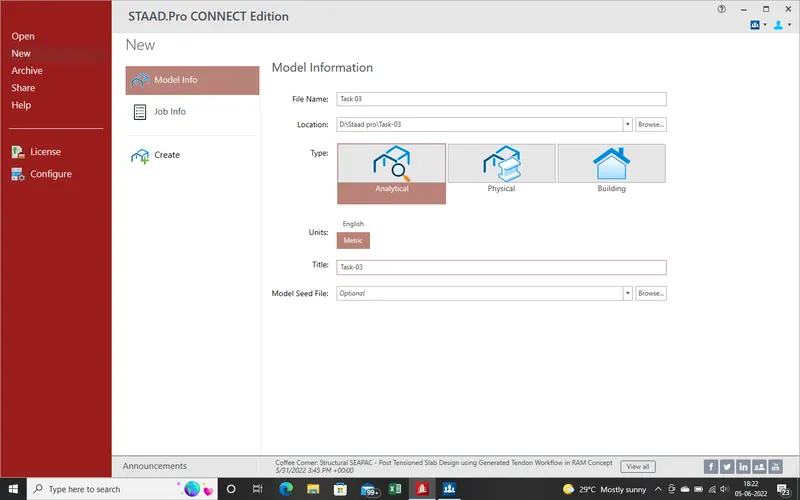
2.Take the Name of File as "Task-03" and loaction fix in "D" and After that set the unit as "metric" as showing in given below pic.
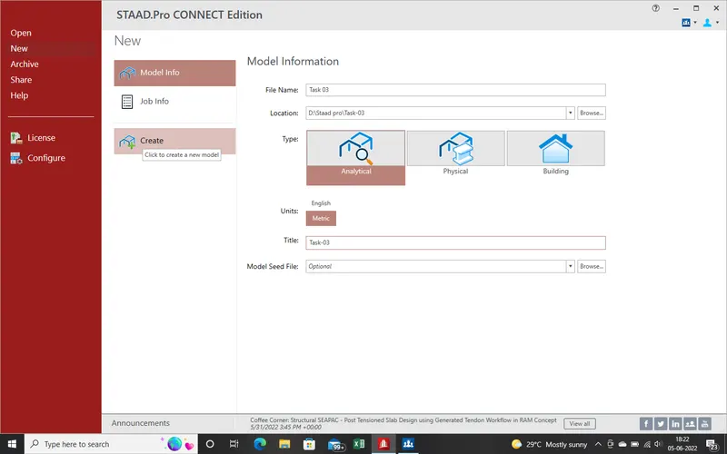
3.Click on "Create" and A new window will open at Staad Pro.
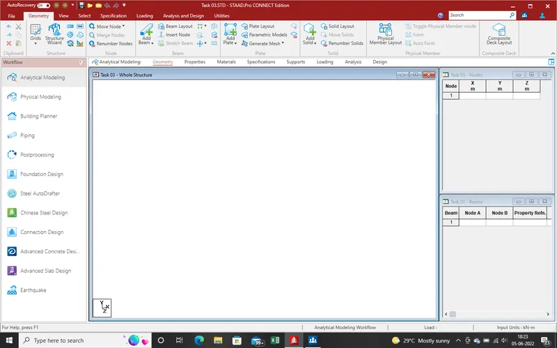
4.Now Draw the node for draw the model. Starting of Model will be 0,0,0.
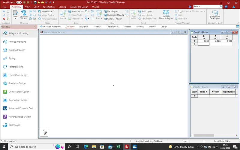
5.Put the values for X-direction as length of Bridge and in Z-Direction will the Width of Bridge. As per Given Data of Bridge the length 25m and Width 27.575. Put the values for nodes as given pic.
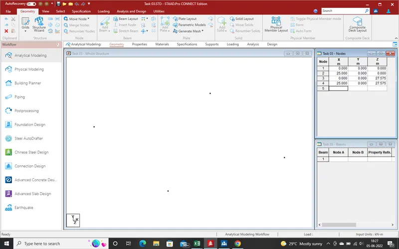
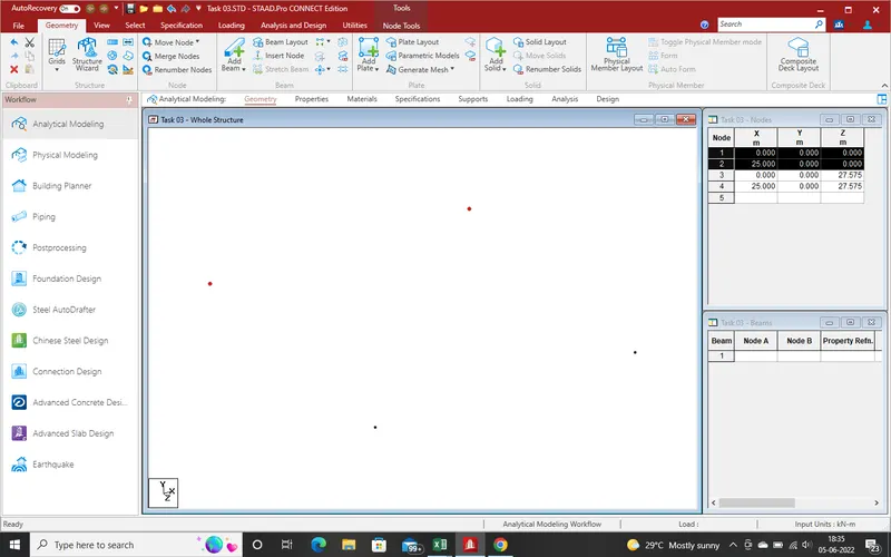
6.Draw the Girder By using the outer node Select the Node and Copy Paste with the help of Translation Repeat Command.For Translation Repeat Command select the node with help of Select Command and Select the Node Cruser and With the help of "Contro" command Select the Node.
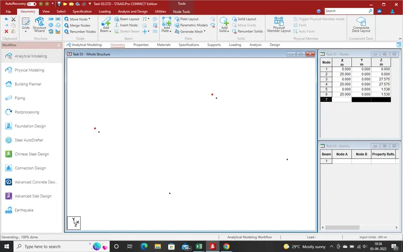
7.As per Given Data From Centre of Girder to outer Edge of Slab is 1.538 m put the value in Z-Direction and Step only 1 step due to girder to Girder Distance Are same.
8.Let the Assume that End Diaphragm Centre from the outer Edge of Slab is 0.500 and that point also be use as pinded Support due to Bearing.So Again use of Copy Paste Command Create the end diaphragm centre at main Girder from Edge to 0.500m .
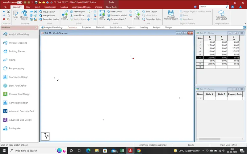
9.Draw the Main Girder with the help of Beam Command.Click the "Add Beam" and create the beam from outer edge to outer edge of slab as showing in Pic.
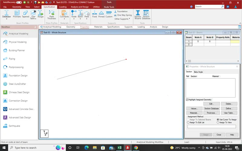
10.Provide the Properties with the help of "Properties" Section and after that Select "Prismatic " and select the I beam Data as Assume in Given Pic.
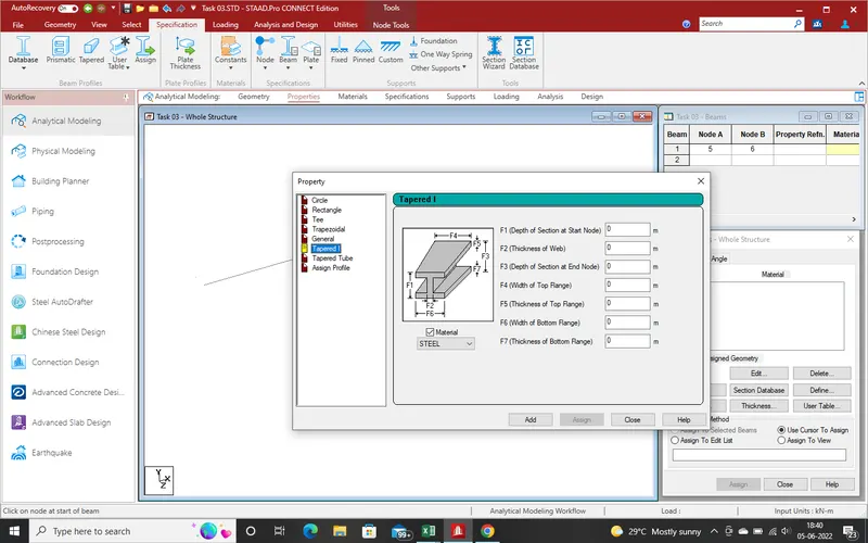
11.Put the Given Values and Material as "concrete " and After that Click on "Add".
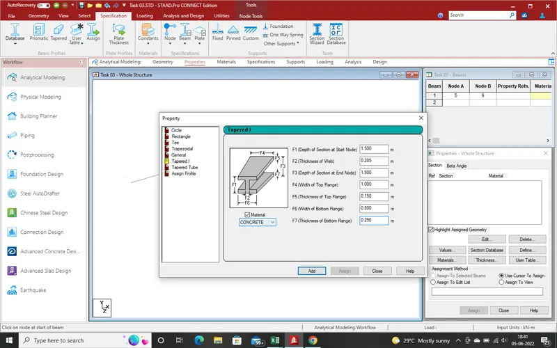
12. After Close the window in Side Task "properties" Section get the the Property for Assign. Select the Beam Where Want to apply the Proprty and "Assign To Selected Beams " And Assign.
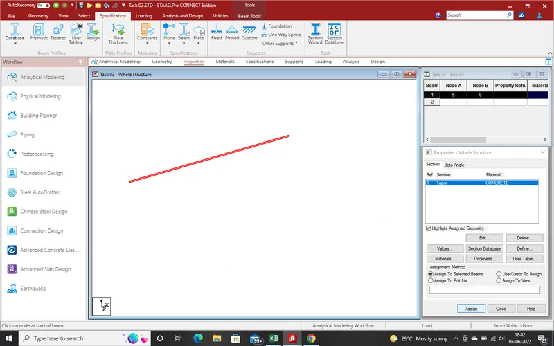
13.After Assign the beam for apply the properties, again it will confirm again that you are selecting right as showing in given pic, as "The Assignment method you have chosen as Assign to Selected Beams. Do you want to Procced ?".
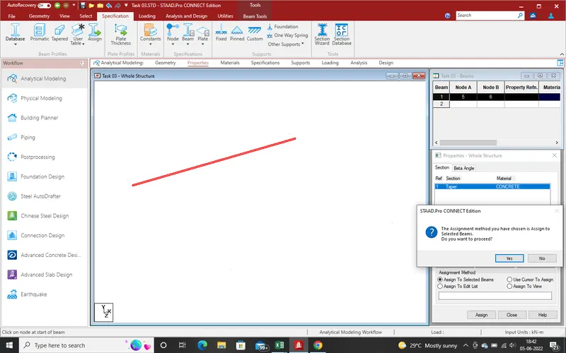
14.After Conformation As "Yes" and Get the Result As Properties applied to Selected Beam as Showing in Pic.
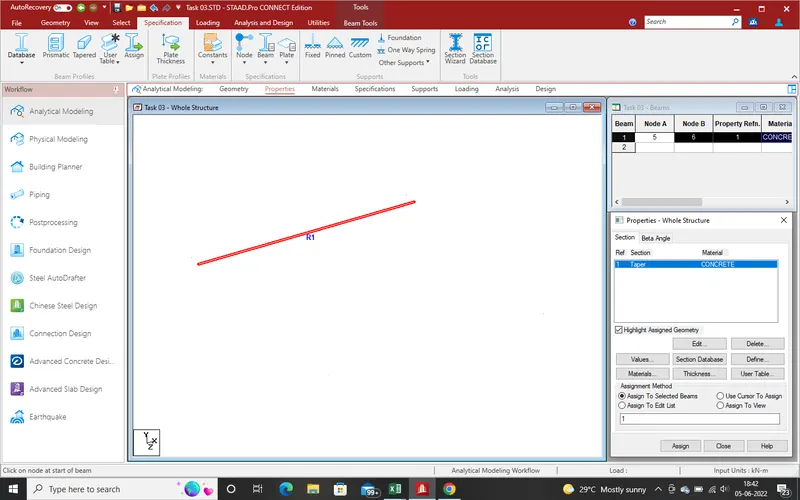
15.For Draw Remaining Girder As Specified Spacing As Per Drawing, use the translation repeat Command.Select the Beam for Copy as "Select"Section and Use "Beam Crusor" and Select the Beam as Showing in Pic.
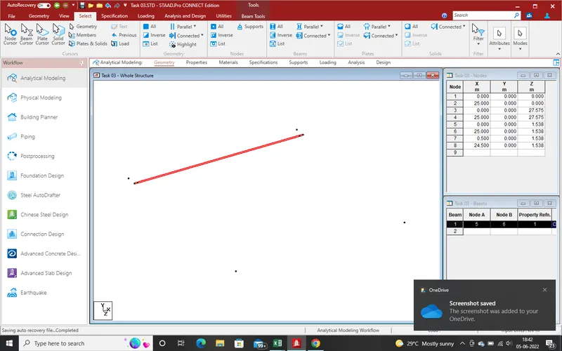
16.Now Go to "Geometry " section and Select the Translation Command , After Click on Translation Command,A new window has been open on main Task Select Direction for Girder as here girder should be in z-direction from select beam then Select "Z-Direction " no step for no of Girder as total no of Girder 8 but 1 girder already has been Drawn, then need only 7 girder required. So put the value as 7 and Spacing of Girder is 3.5m. then put values of Spacing is 3.5m.
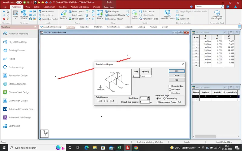
17.After fill all the values need to Click on "ok" For Confirmation that Data which Have been Provided are ok.
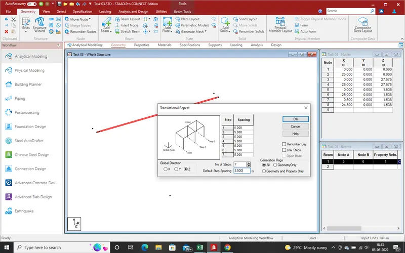
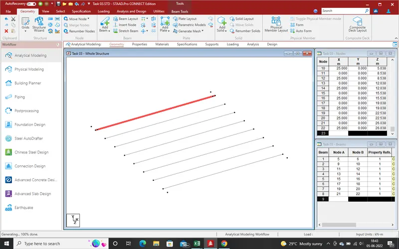
18.As provide the values, get the results as shown in given pic.
19. Now need end Diaphragm for connect the Main Girder.For End Diaphragm need Node for Draw Beam.We use the Translation command for Create the node.Select the Node which need to draw on main Girder as shown in given below pic.
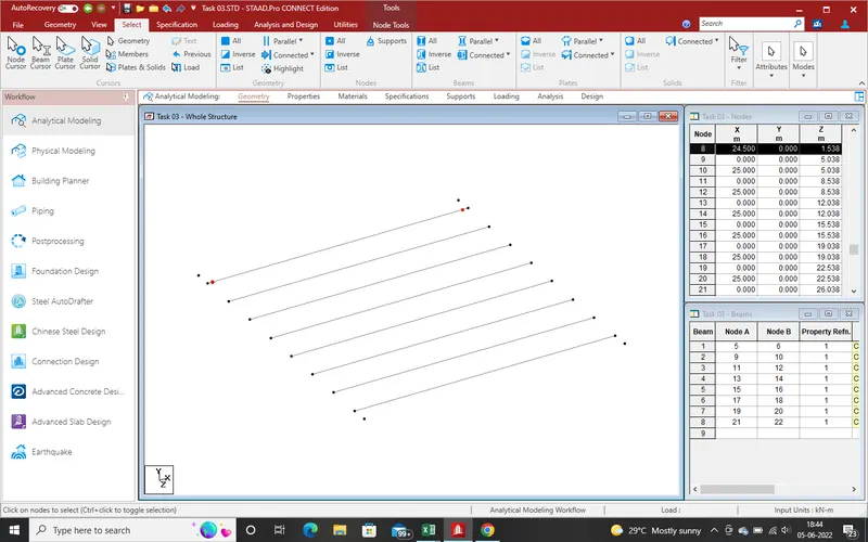
20.As Same As In Pervious The time of Main Girder select the Direction as Z-direction, Spacing of Girder are 3.5m and no of steps are 7 as showing in given below Pic.
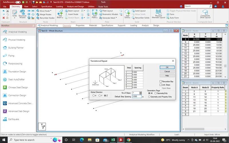
21.After put desired values we get the Result as per Drawing Data as showing Pic.
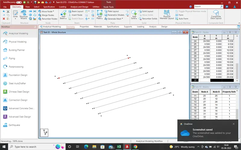
22.Select the "Add Beam " Command and Draw the End Diaphragm as given below pic .
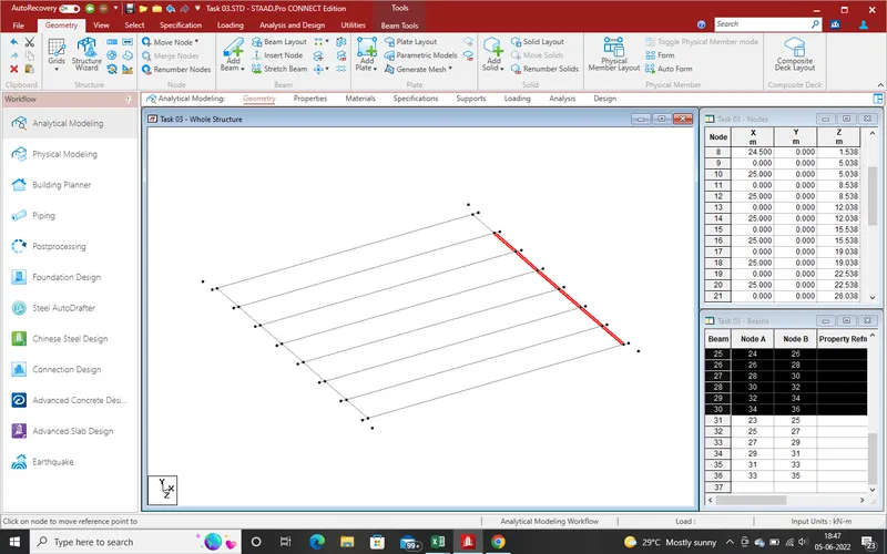
23.Go to "properties Section" for Define and Apply end diaphragm Properties as per Drawing data .Select the "properties " section,Select the Prismatic Section for End Diaphragm.
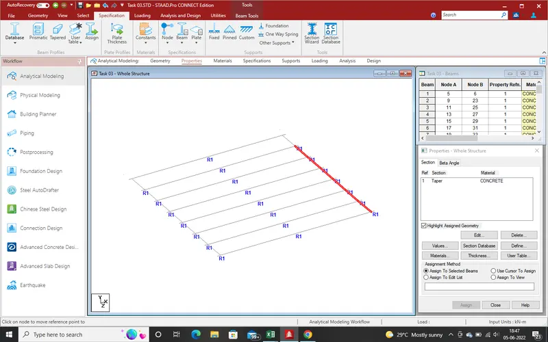
24.Select the "rectangular" section for end diaphragm and put the values as assume that depth of beam is 1m and Width is 0.4m. After Click on Material as"Concrete" and Click on "ok" for Add Properties in property section For Apply the property to Concern section.
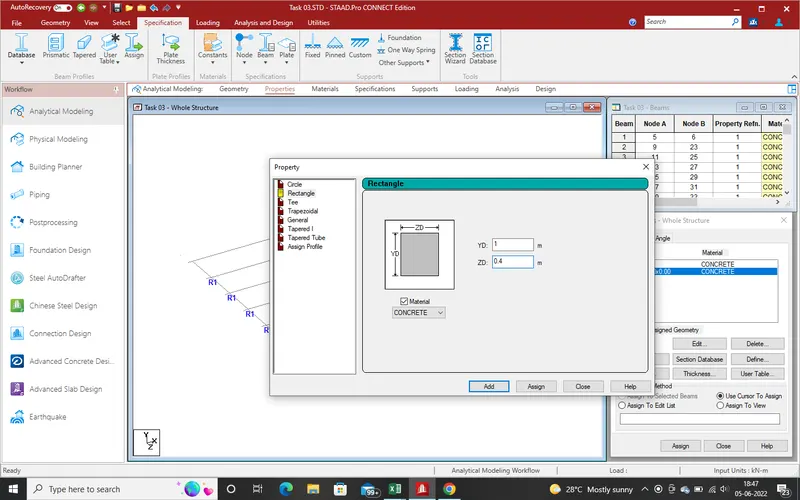
25.Defined Property has been Add in Property Section.Now Select the Beam for Apply Property From Select Section as Beam crusor for Select the beam,and Select the beam.Select the property which want to Apply as 3.Rec. 1*0.4 and Click on "Assign To Selected Beam".
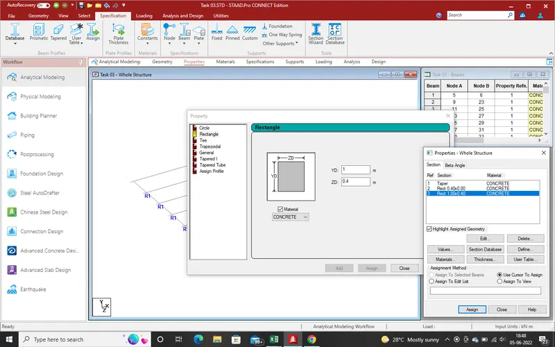
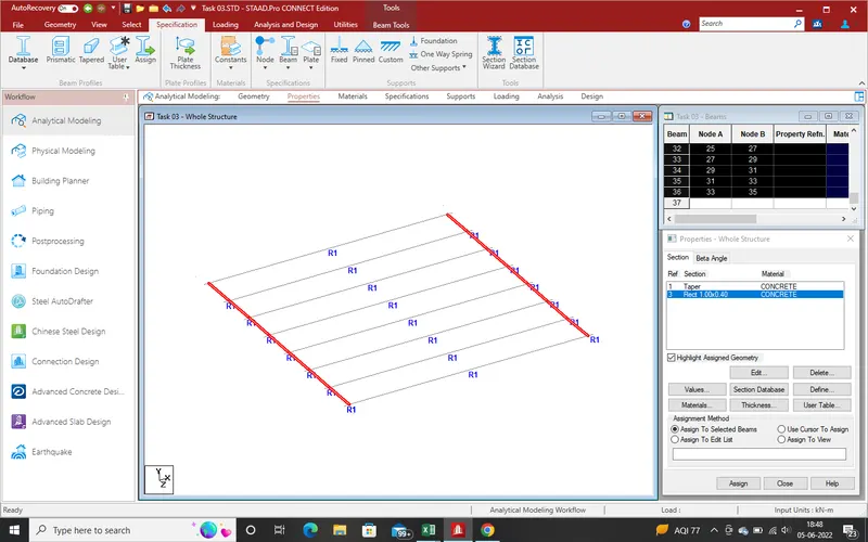
26.After Select "Assign To Selected Beam" and Click on Assign and get the Conformation bar for Conformation after click on "Yes" Properties As been applied to slected beam as Shown in Given pic.
27.Now a dummy Beam Required for Outer Edge of Slab for Connect all Cantilever Slab Section.Select the beam Section and Draw the beam as spaced from main Girder is 1.10m.
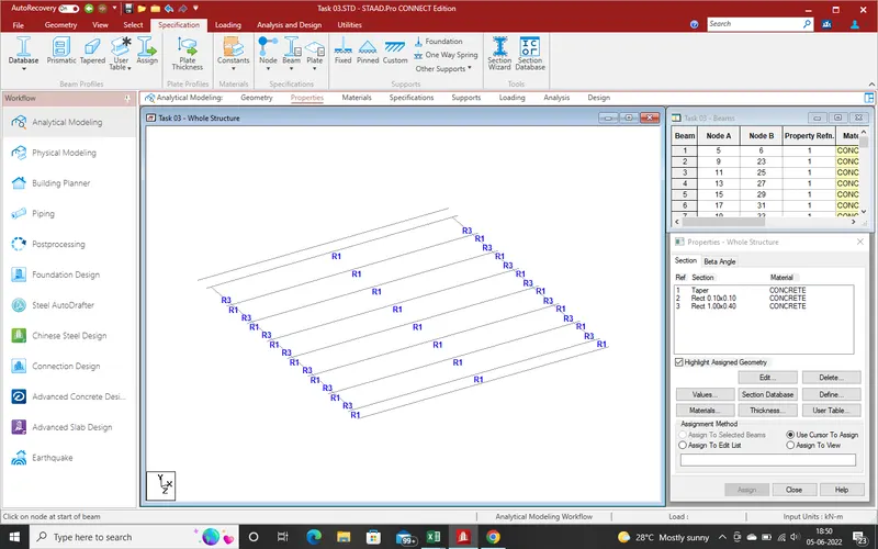
28.Same Process Has been use for Apply Properties as 0.1m with an 0.1m depth for Dummy Beam.
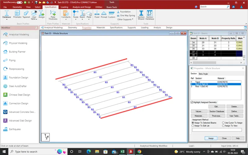
29.Now need the plot the Plate for slab Section.start from cantilver Section.Select the "Add plate" and Draw the plate as shown in given below pic.
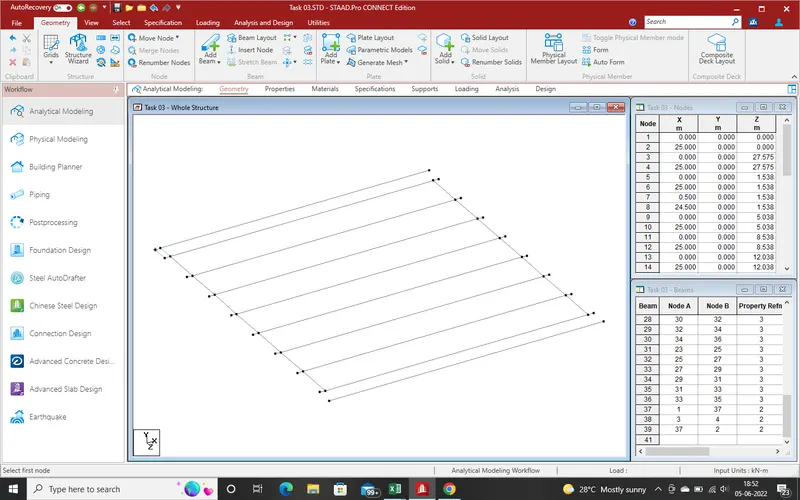
30.Use of Copy Paste command Plot same Plate Section all Corner as showing given below pic.
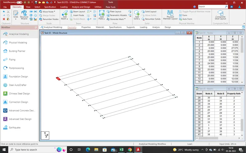
31.Now Change the Direction of view of Model For Copy paste the cantilever section for plot the plate section.and Plot the plates use of translation repeat command.
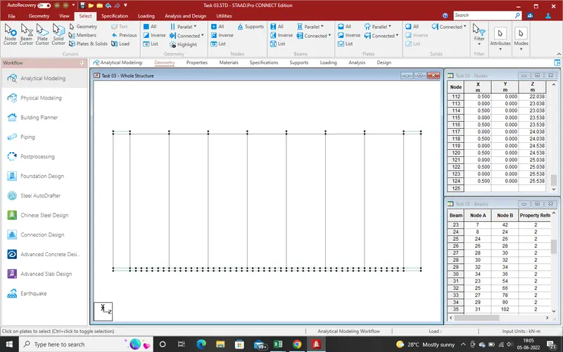
32.Same Process has been use for whole Slab Section and Apply as shown in given pic.
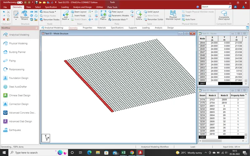
33.now need apply properties for plate Section.Go to "properties" section and Select "plate thickness" for plate Properties .
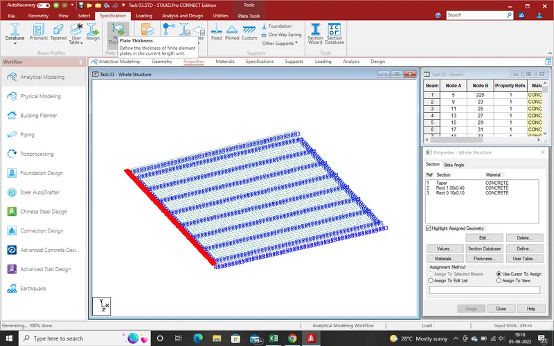
34.After Select Plate thickness, provide the thickness as 0.300m for slab.
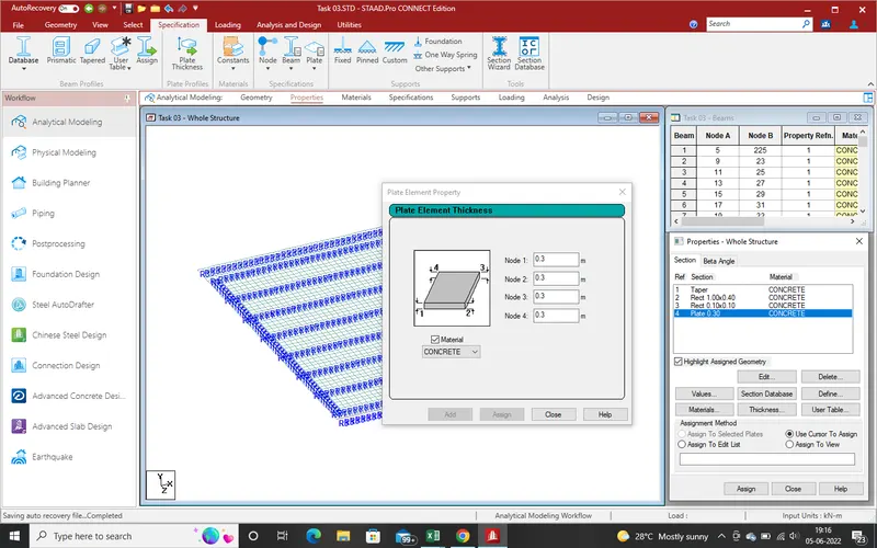
35.After Provide the thickness of Slab Click on "ok".Properties Shall be Add in properties Section.Now select all plates for Assign properties and Assign plates properties.
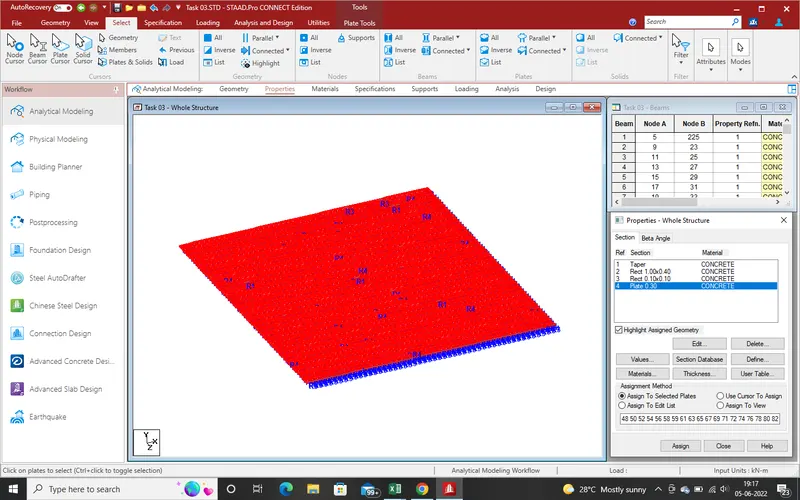
36.All Properties leter need the Support Apply . As Per Drawing in main girder centre are use as potion of support.Now bridge slab support are pinned Support type support . Select the pinned support define as S2 in side support Reaction Section.
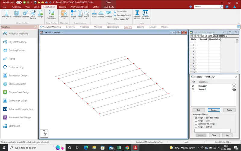
37.Select the ondes where need the pinned support as per given data from model select the node for Apply pinned Support and assign .
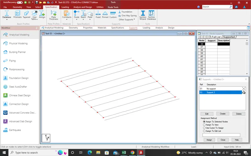
38.As we Apply the support as pinned Support we get the results shown in given below pic.
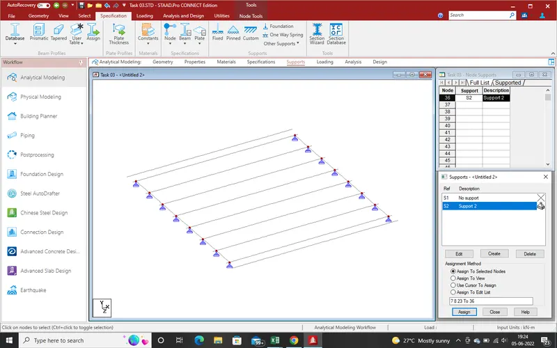
39.Now modelling work of bridge has been Complited now need the checking the error which can be done during modelling.Go to "utilities" section where check the error which detailling will see in next steps as
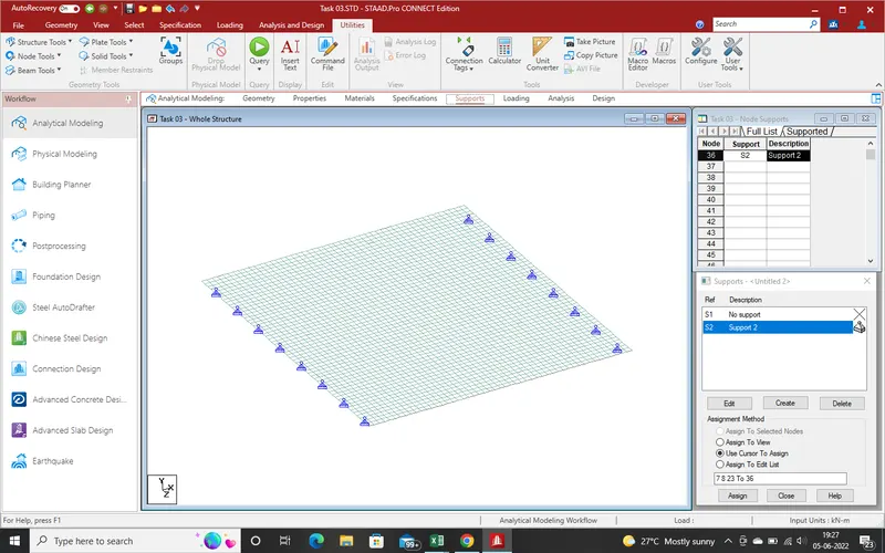
40.In Structure Tool,First of all we check the "multiple Structure", thats means model should be one if more than one that means model need to recheck and resolve the error.
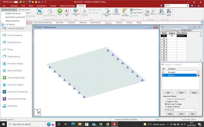
41.Here list of Structure is "1" that means "ok" and clos the window.
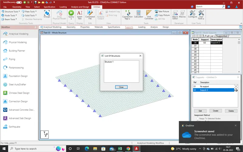
42.Now we check "Beam/Plate Connectivity" ,here need the check the connection between plates and beam.it should be proper connect if no need to remove error by connect proper. here checking Connection in progress as shown in given below pic.
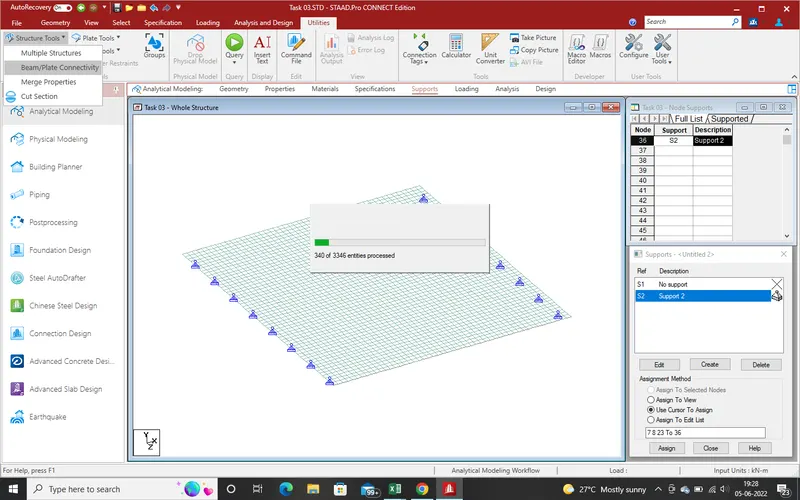
43.As per result there is no "improper member and plates connection found " that means ok. now close window by clicking on "ok" on window .
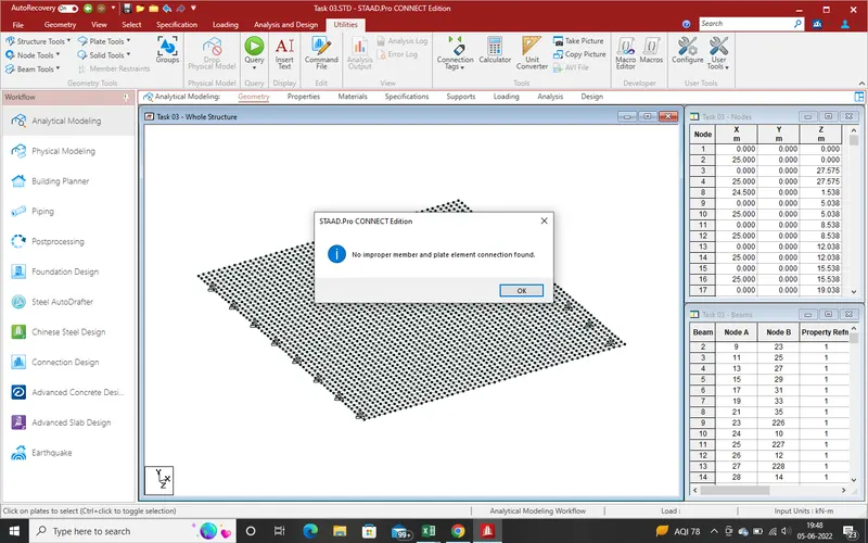
44.Now check the merge properties, and there is no merge properties.
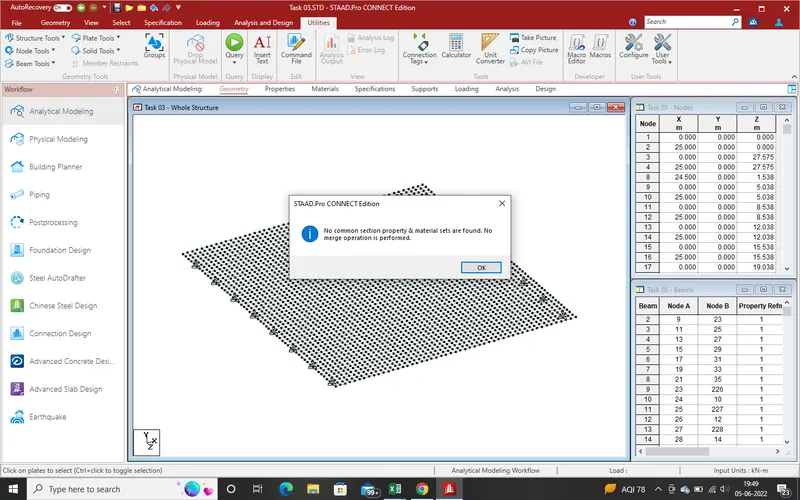
45.Now In node Section check the duplicate node or Bouble node at one location with the help of 0.001m tolerance and click on "ok"
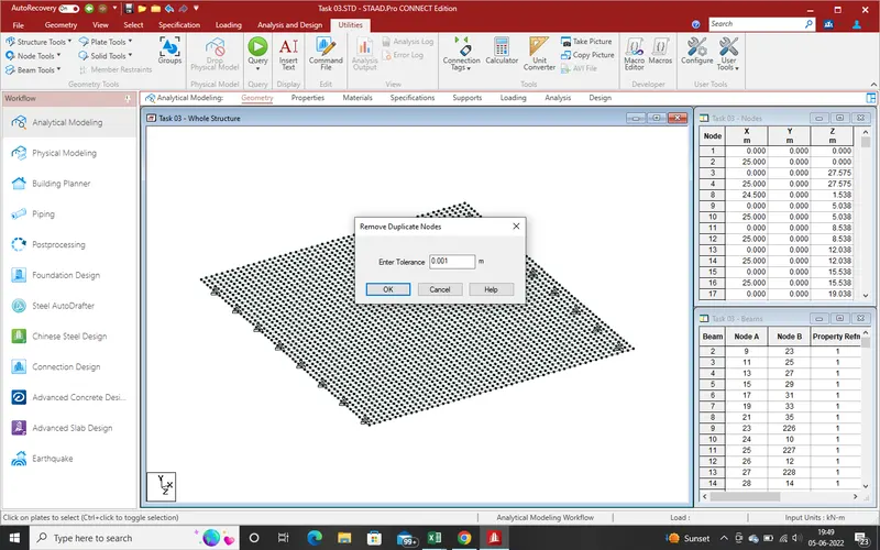
46.And we get the reuslt as there is no duplicate nodes, thats means model is ok.
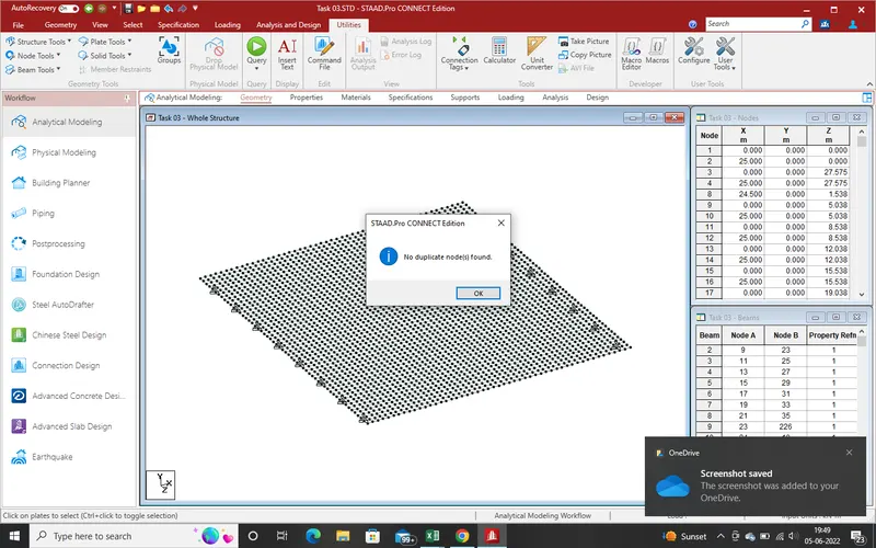
47.Ckeck the "orphan node " which is also not found means "ok".
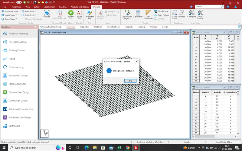
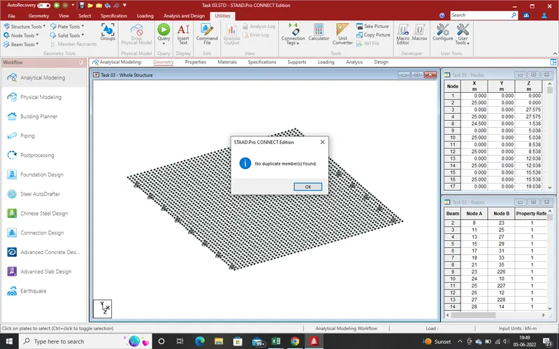
48.Now we check in "Beam Section " ,such as "duplicate Beam " and found there is no duplicate beam, means model is ok .
49.Now we need to Find the zero length beam and apply the tolerance as 0.001m and click "ok".
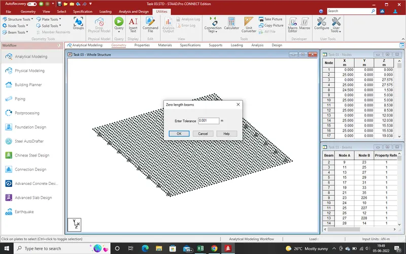
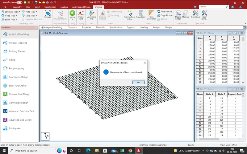
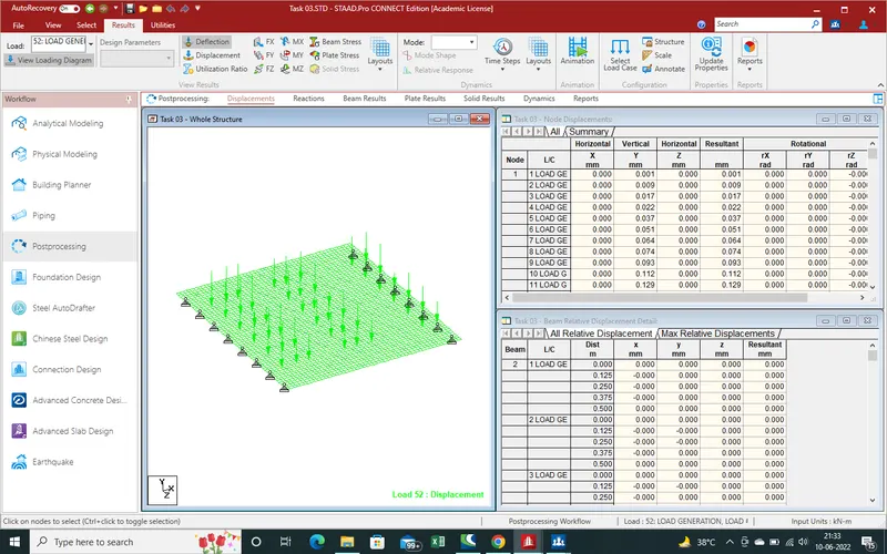
50.And we found that there is no "zero length" ,means model ok .
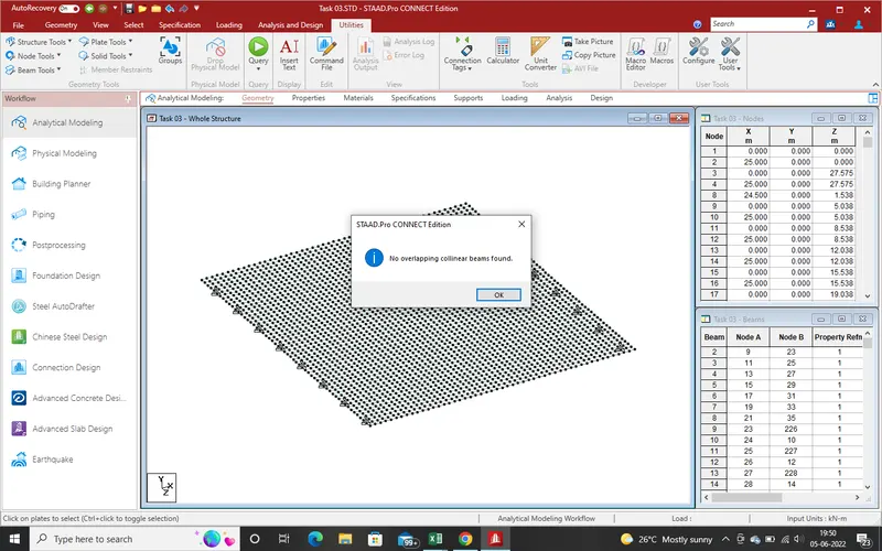
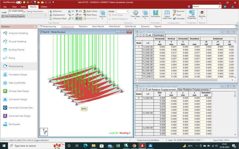
51. Same as there is no overlapping beam.
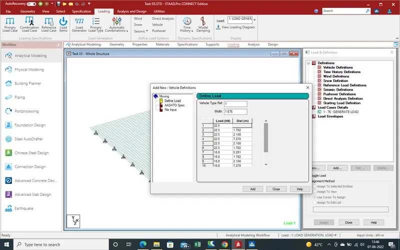
52.Now we move next most important step as "loading" for Apply the live load as per IRS code on model.Go to Defination section in which select the "vechile Defination" section,Click on Add a new window will open as shown as given below pic. Put the values as width as 1.676 for broad gauge section. Put the load at prticular spacing spacing as per IRC code and Click on "add"and close the window .
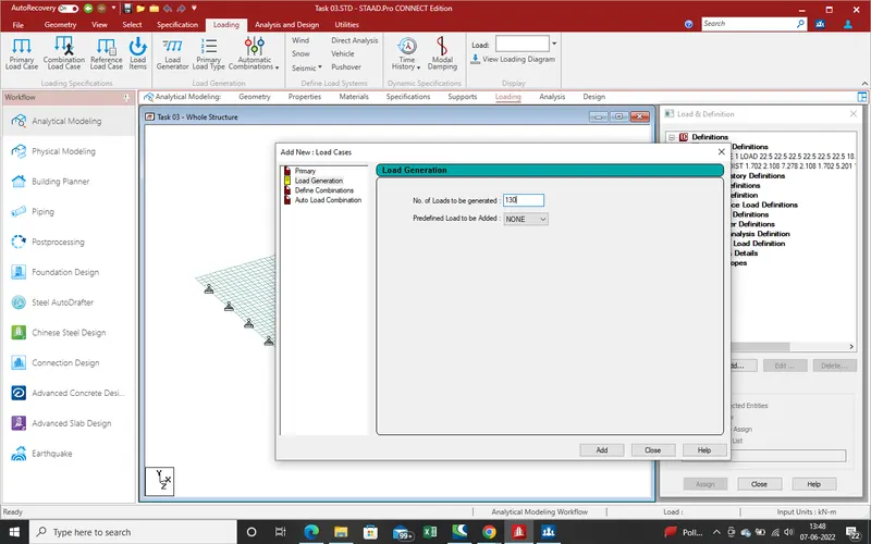
53.Now Apply the Define Load on Slab As per Drawing, For loading select "Load Cases Details". Select the no of load as 130 due to slab+loading vechile length devided by spacing which is 0.500m.
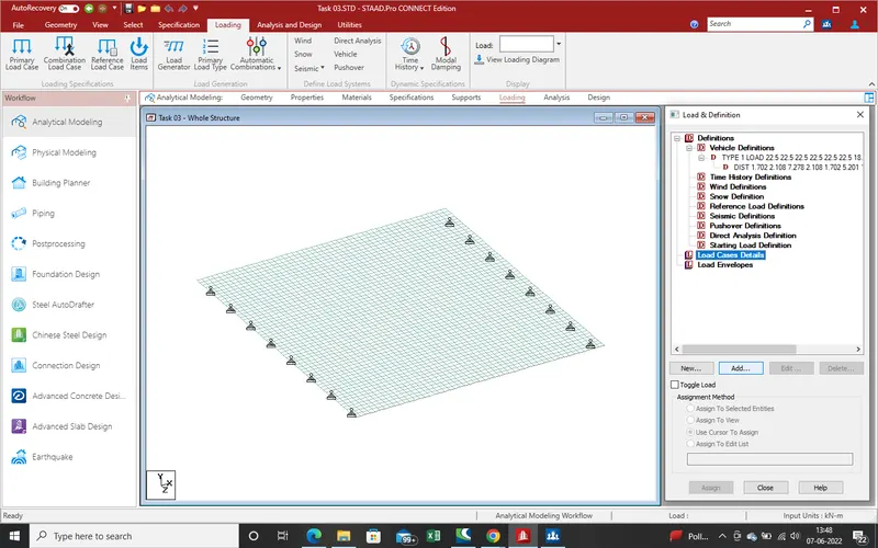
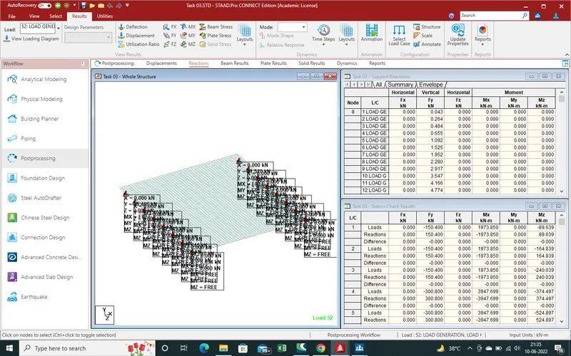
54.Total No of Loads by using with help (length of loading boggi+span of bridge )/spacing of loading. here length of boggi are 40m, span is 25 m and spacing is 0.5m so we get the approximately 130 no. Click on "ok" for Add load genation.
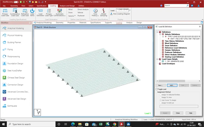
55.Load Cases Details has been Created, now need position of loading.for select the position with the add case in new in "generated load" click on "Add".
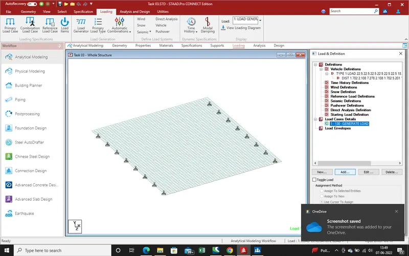
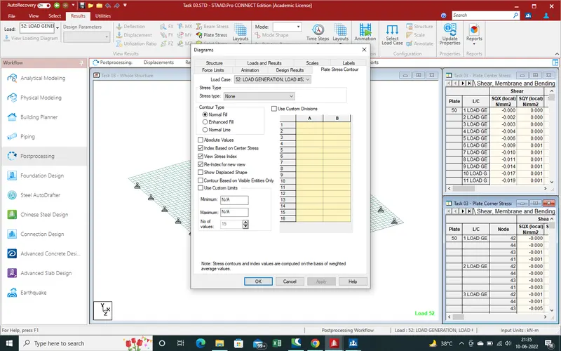
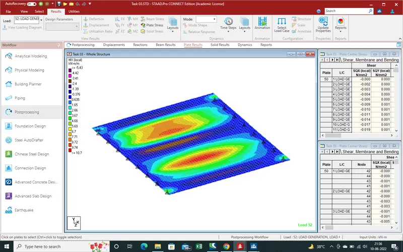
56.Now put the postion load position as per drawing, in X-direction values put in negetive(-) due to boggi will start from zero as there -34.350m and z-direction values are 6.462m due to 1st track from outer edge distance. load increment are 0.5m as we specified here and click on "add"
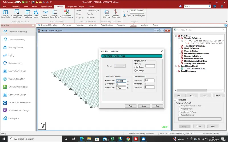
57.As per Drawing there is 4 loading for IRS loading.So 2nd loading spacing from outer edge are "10.062m" and remaining data will same and Click on "Add".
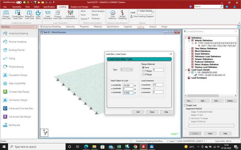
58.Same Prosses will done done for loading at 3rd and 4th loading as showing pic.
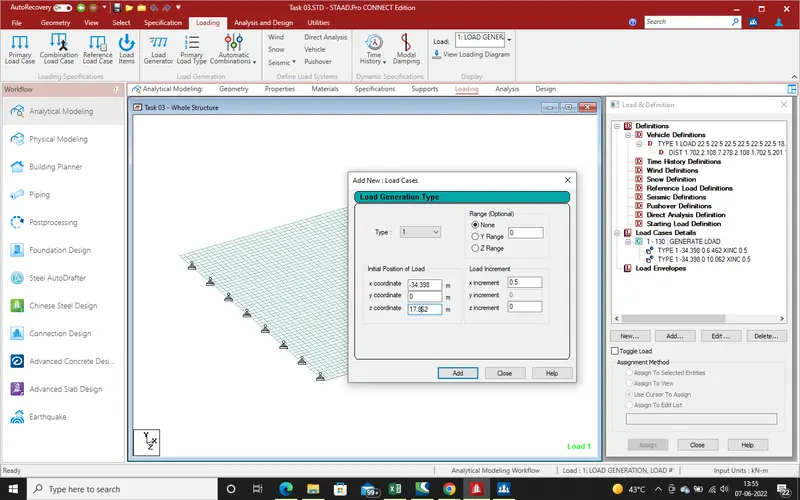
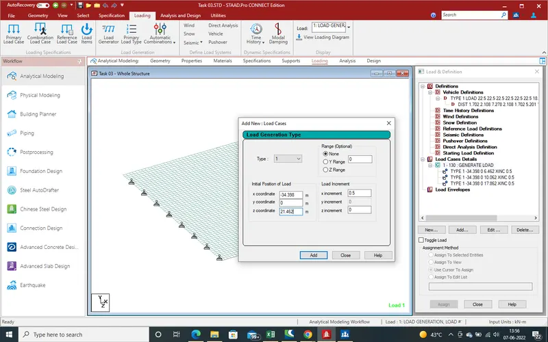
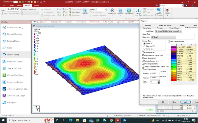
59.All Loading has been done and successfully done, Now will need to run the analysis for get the result.
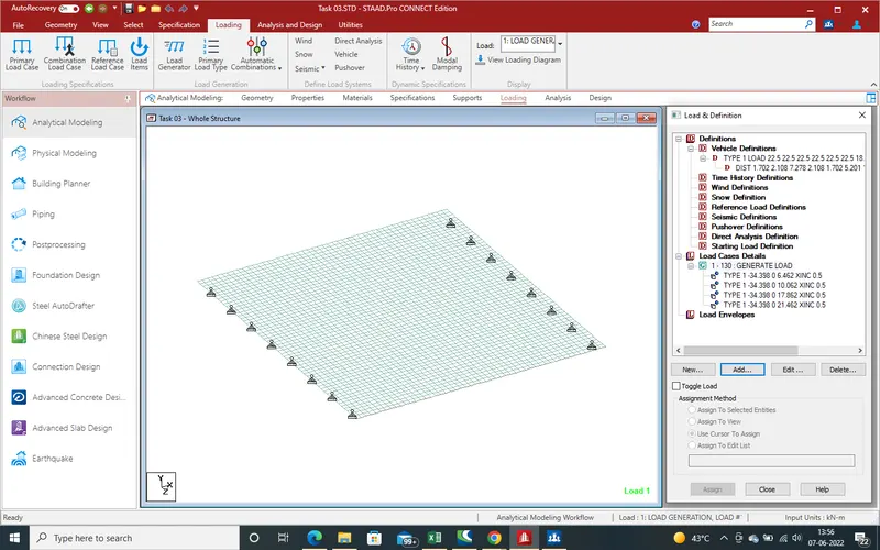
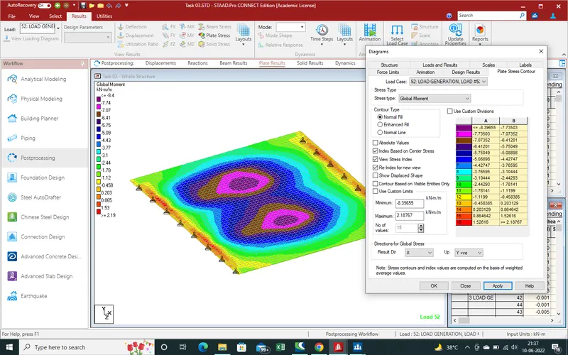
60.Click on "Analysis" Click and Add "Perform Analysis " for get the result .
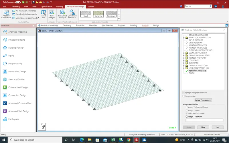
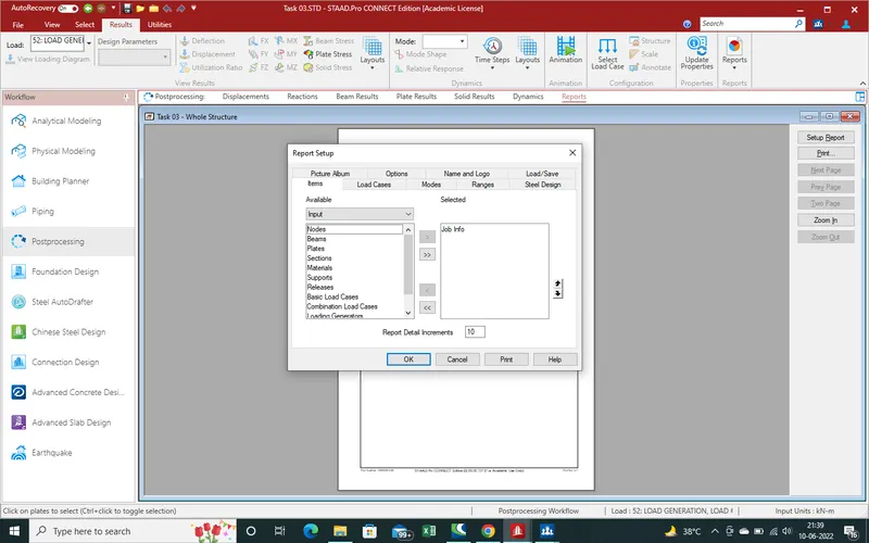
61.Now click on "Run Analysis", as click on "run analysis " a new window has been apear "Structure has been modified" click on "Save " as showing in given below pic.
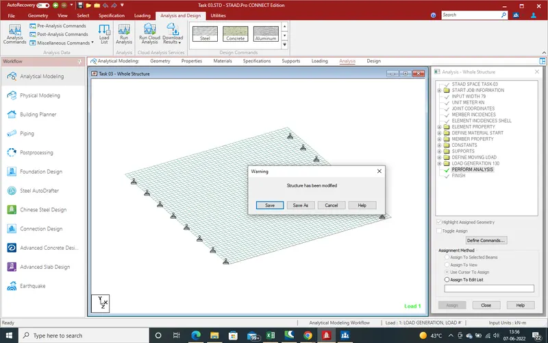
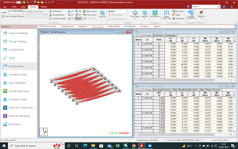
62.Analysis has been started it will take some time .
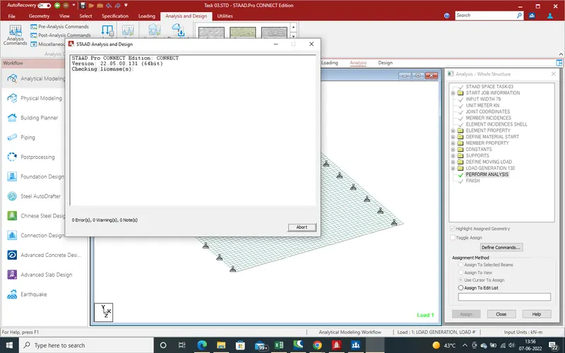
63.After Analysis,there is no error so we can take as next step for "postprocessing" .here can be find out the displacement due to live loading with respect to location and can be find out max and min displacement .
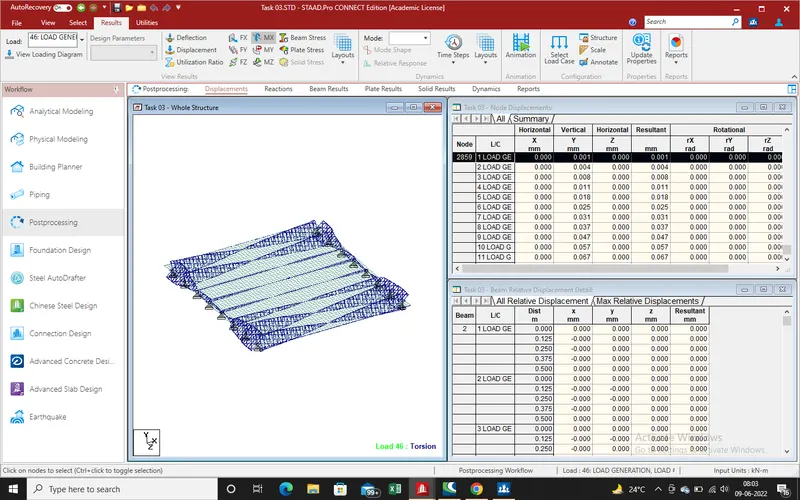
64.Displacement due to shear force in Y-Direction
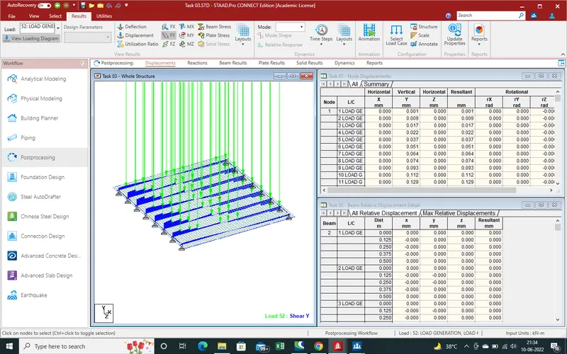
65.Dispalcement due to "Moment with the respect to X-direction ".
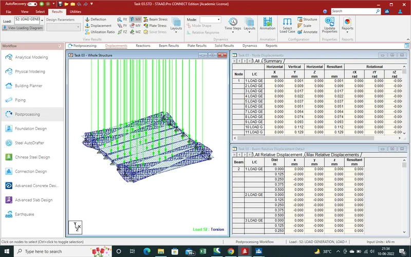
66.Displacement due to "moment in respect to z-direction".
67.Support Reaction due to live load as per IRS loading.
68.Support Reaction due to "Moment in Z-direction".
69.Plates reaction for Different loading reason like,
70.
71.plate reaction due to MY(local) moment in Y-direction
72.Plate reaction due to global moment
73.Now get the report in all in one ,go to report select on"setup " section and select which input required.
74.Displacement due to Diflection
75.From all Step we can get the Deflection,shear force,moment results for displacement, beam reaction same as for support and plates section .
RESULTS & CONCLUSION:-With the help of Staad Pro we can easly found out Live Load Reation as proper follow the steps. here attached the results on 25m span slab due to MG line on Bridge .
here the attached the copy for model rechacking and results report for Results.