Week 11 Car Crash simulation
Car Crash Simulation
Brief:
A crash simulation is a virtual recreation of a destructive crash test of a car or a highway guard rail system using a computer simulation in order to examine the level of safety of the car and its occupants. Crash simulations are used by automakers during computer-aided engineering (CAE) analysis for crashworthiness in the computer-aided design (CAD) process of modelling new cars. During a crash simulation, the kinetic energy, or energy of motion, that a vehicle has before the impact is transformed into deformation energy, mostly by plastic deformation (plasticity) of the car body material (Body in White), at the end of the impact.
Data obtained from a crash simulation indicate the capability of the car body or guard rail structure to protect the vehicle occupants during a collision (and also pedestrians hit by a car) against injury. Important results are the deformations (for example, steering wheel intrusions) of the occupant space (driver, passengers) and the decelerations (for example, head acceleration) felt by them, which must fall below threshold values fixed in legal car safety regulations. To model real crash tests, today's crash simulations include virtual models of crash test dummies and of passive safety devices (seat belts, airbags, shock-absorbing dashboards, etc.). Guide rail tests evaluate vehicle deceleration and rollover potential, as well as penetration of the barrier by vehicles.
Crash simulations are used to investigate the safety of the car occupants during impacts on the front end structure of the car in a "head-on collision" or "frontal impact", the lateral structure of the car in a “side collision” or “side impact”, the rear end structure of a car in a "rear-end collision" or “rear impact”, and the roof structure of the car when it overturns during a "rollover". Crash simulations can also be used to assess injury to pedestrians hit by a car.
AIM: To perform an explicit dynamic analysis of a frontal car crash set up using Ansys workbench for 3 different values of thickness for the car body and analyse the total deformation and Equivalent stresses acting on the model.
CASE I: 0.3mm
CASE II: 0.5mm
CASE III: 0.75mm
PROCEDURE:
- Create Explicit Dynamics Analysis in Ansys workbench and set up the given geometry.
- Open the Model workspace and assign the thickness to the car body. Here, we are using 3 different values of thickness.
- To perform the same simulation for varied thicknesses, there need to check on the box for "Thickness" in the details of a car body.
- As the body is performing under dynamic analysis, we assign the non-linear structural steel material to the car body.
- Fix the rear part of the body which is not in contact with the wall and have an effect on the simulation.
- Remove the pre-defined existing contacts provided by the Ansys workbench.
- Add displacement of 500mm on the wall for the runtime of about 0.001 sec.
- Apply tetra mesh with an element size of 150mm and also to save the simulation time, a coarse mesh is applied to the rear parts of the car.
- Symmetry regions are created for the wall and car body to reduce the computational time.
- For the output parameter, the total deformation and equivalent stress & directional deformation are set.
Material Properties:
Stainless Steel NL
The result page for the parameter set page appears:
Simulation test results:
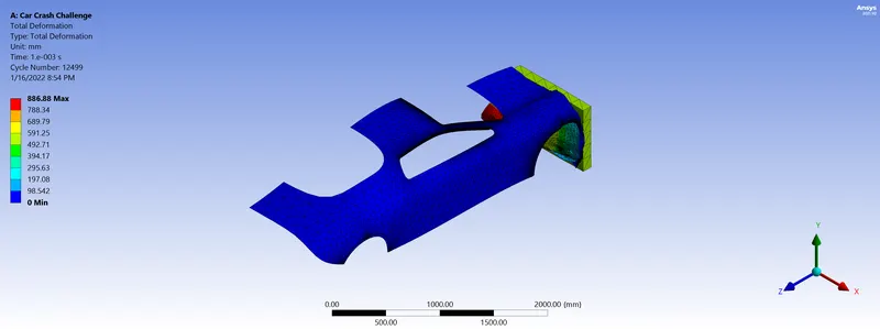
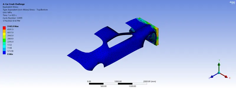
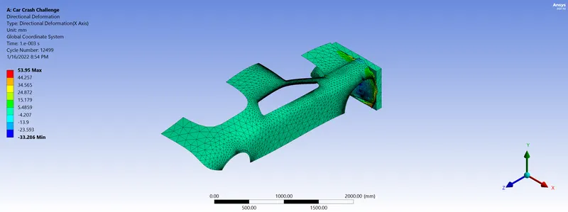
Case I:
Total deformation:
Total equivalent stress:
Directional deformation:
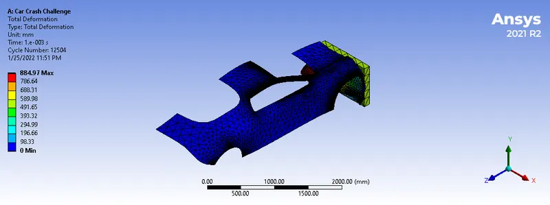
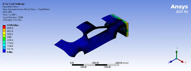
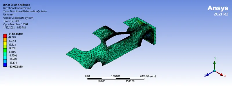
Case II:
Total deformation:
Total equivalent stress:
Directional deformation:
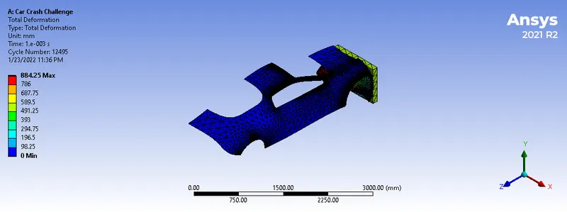
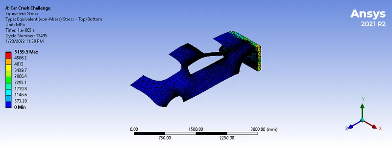
Case III:
Total deformation:
Total equivalent stress:
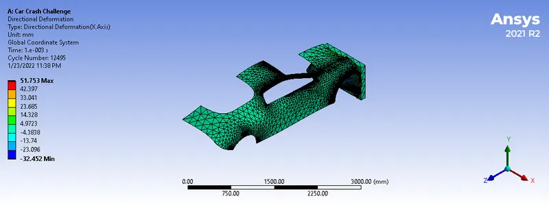
Directional deformation:
RESULTS:
| Case Test | Total Deformation | Total Equivalent Stress | Directional Deformation |
| Case I | 886.88mm | 5165.9 MPa | 53.94mm |
| Case II | 884.97mm | 5158.8 MPa | 51.81mm |
| Case III | 884.25mm | 5195.5 MPa | 51.753mm |
CONCLUSION:
- Maximum deformation is developed for Case I because for the lowest stiffness or rigidity to resist deformation.
- Maximum stress is developed for Case I because it has a minimum thickness so induces maximum stresses due to less resisting area. The model experience the highest Von-Mises stress when the thickness of the shell is the least.
Video links: