Week 11 Car Crash simulation
OBJECTIVE: To perform explicit dynamics analysis by applying 3 parametric values to the car body's thickness and obtaining the required result in ANSYS.
CASE 1: 0.3 CAR BODY THICKNESS
PROCEDURE:
- Open Ansys Workbench and choose Explicit Dynamics from the toolbox.
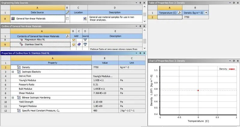
- In the Engineering data, let the material be Structural Steel and also choose Stainless Steel NL from the General Non-linear Materials.
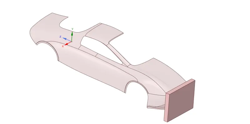
- For the geometry, right-click and import the given "carbody_wall.STEP" and open with space claim.
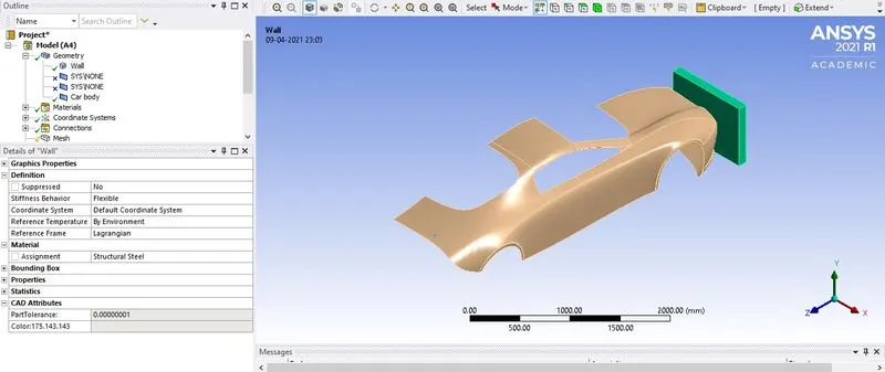
- Now in the workbench goto Model -> Edit, in the model window check the Geometry for the material and assign Structural Steel to the Wall and Stainless Steel NL to the car body component also assign the thickness value 0.3 mm to the car and select the Parametric to assign different values.
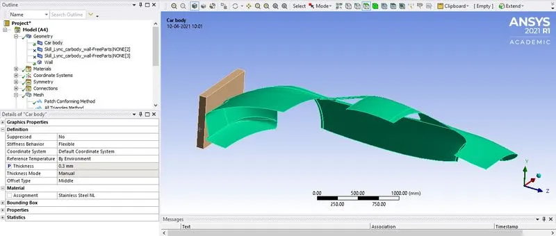
- As the car body and wall is half of the part so symmetric needs to be applied, a symmetry region is added to the face of the wall one along the x-axis and for the car's body edges are selected along the x-axis by clicking on Model-> Prepare -> Symmetry ->Symmetry region.
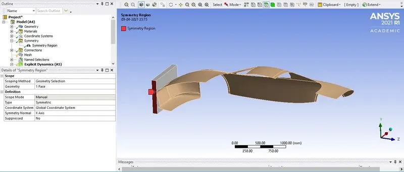
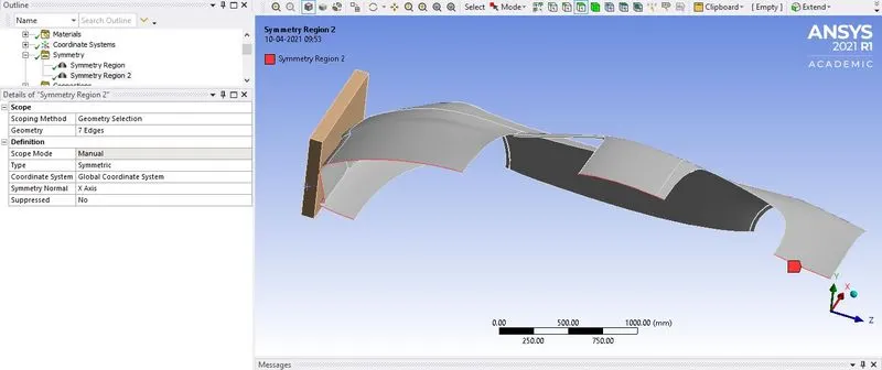
- In connections delete all the available connection, choose Body Interaction for geometry= All bodies and type= Frictionless.
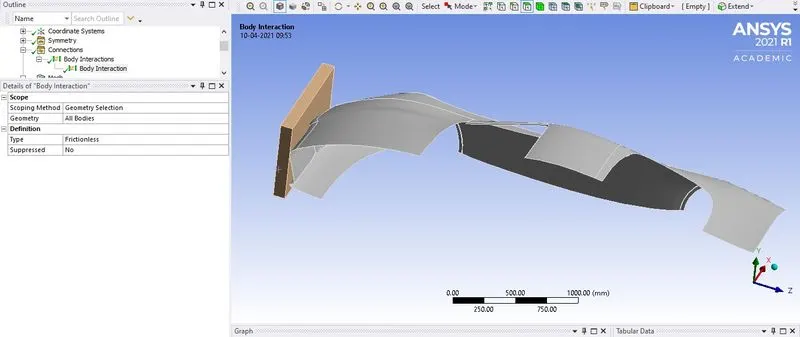
- For mesh, select the method and apply to the wall Method= Tetrahedron, Algorithm= Patch Conforming.
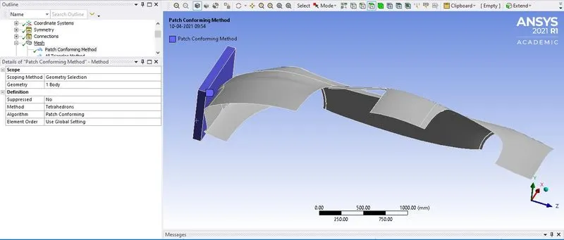
- Select the method and apply it to the car body Method= Triangles.
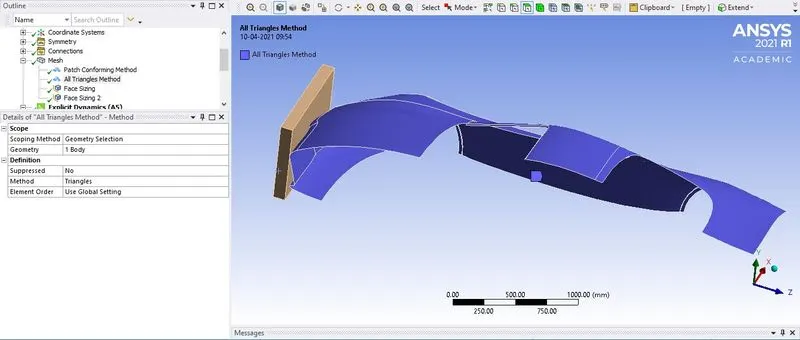
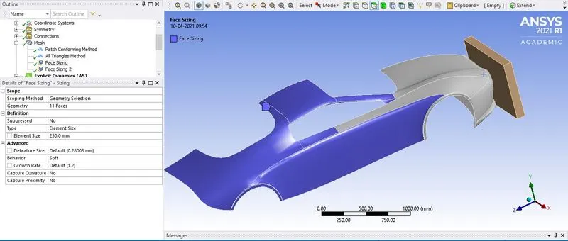
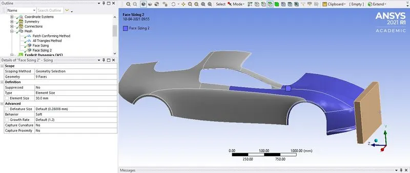
- Face sizing is applied to the car in 2 different ways one for the rear part of the body which will not come in contact with the wall while being displaced and for that element size applied is 250 mm and for the front part which will come in contact with the wall, the element size is 30 mm.
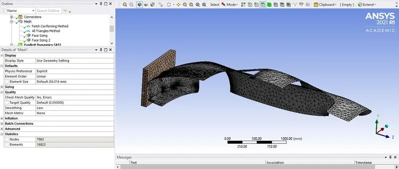
- Before mesh is generated the quality of the meshing is set to the Low, click on generate mesh.
- For analysis setting, Load Step Type= Explicit Time Integration, End time= 0.01 s, Max. Number of cycle= 1e+7, Maximum energy error= 0.1.
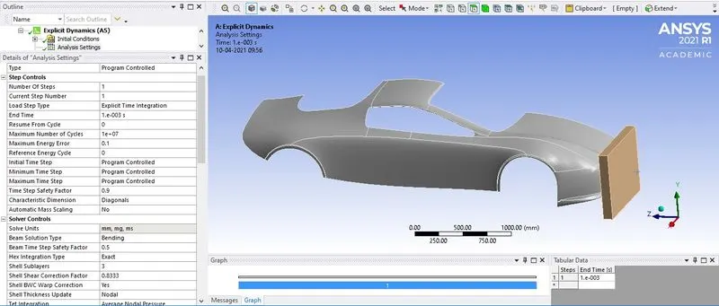
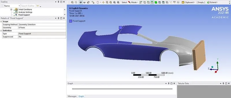
- Apply foxed support to the rear end faces of the car.
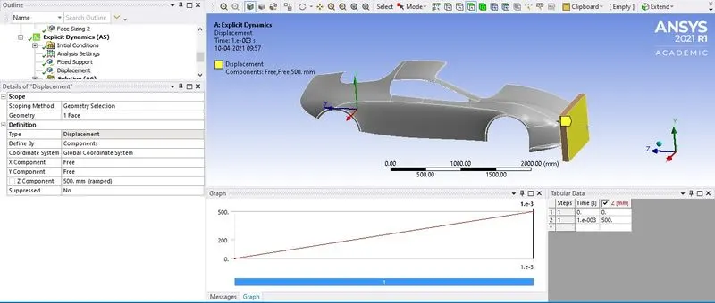
- Apply displacement to the rear face of the wall in the Z component with a value of 500 mm.
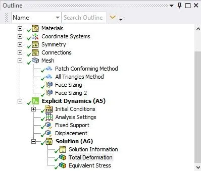
- In the solution request select for the required output like Total deformation and Equivalent Stress and for the max value click on Parameter so for different thickness the required values can be determined. Click on solve to generate the result
CASE 2: For Parametric Value
- To assign parametric values on the project page select Parameters and assign design points DP1 as 0.5 mm and DP2 as 0.7 mm. Click on Update All Design Points to solve for that values.
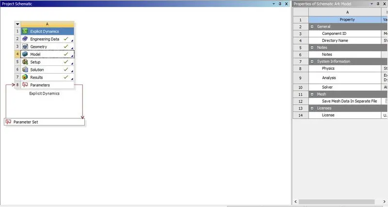
- After solving click on the design point and make it current and open the model edit in the project page to view the results.
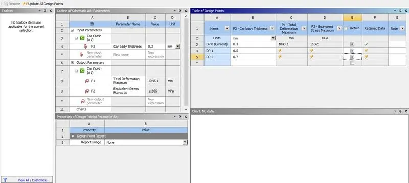
RESULT:
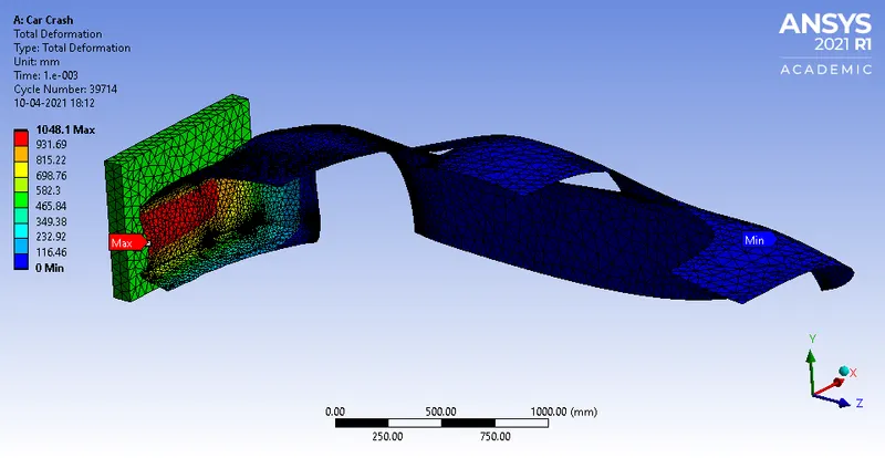
Total Deformation
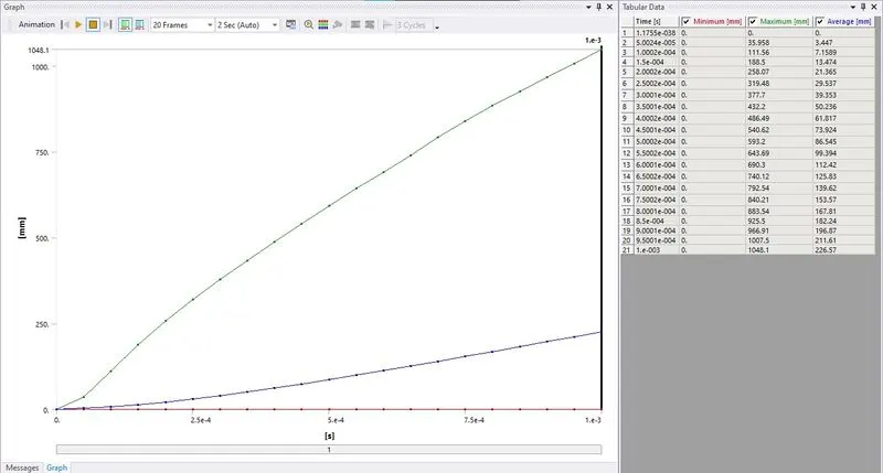
CASE 1: 0.3 mm Car's Body Thickness
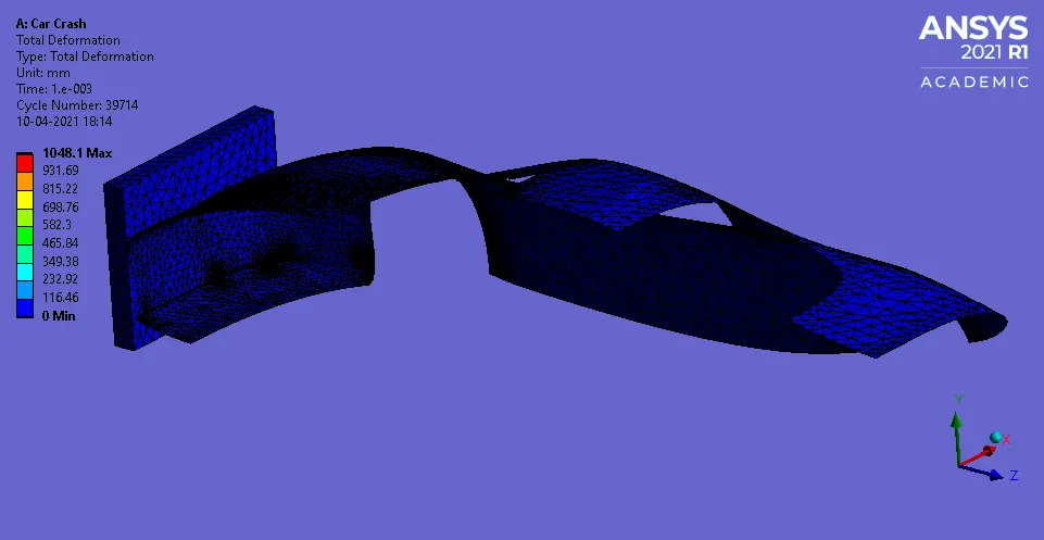
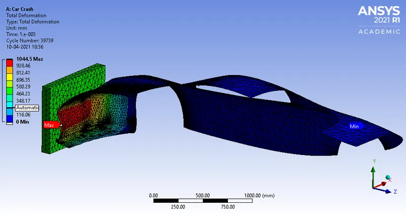
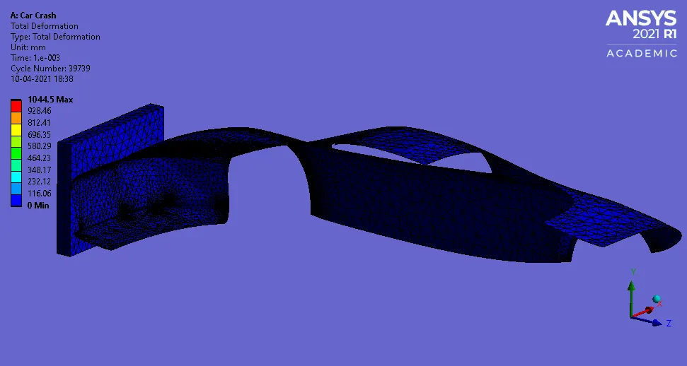
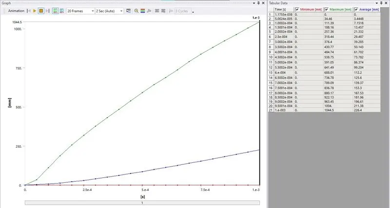
CASE 2: 0.5 mm Car's Body Thickness
CASE 3: 0.7 mm Car's Body Thickness
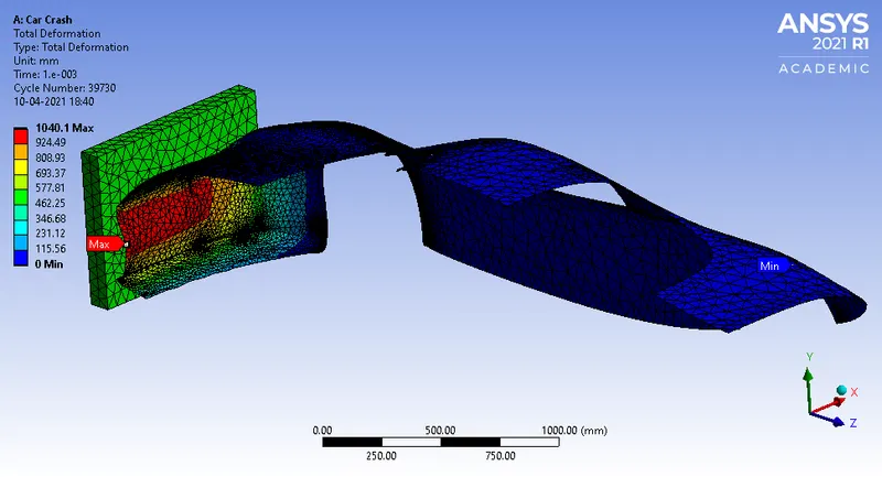
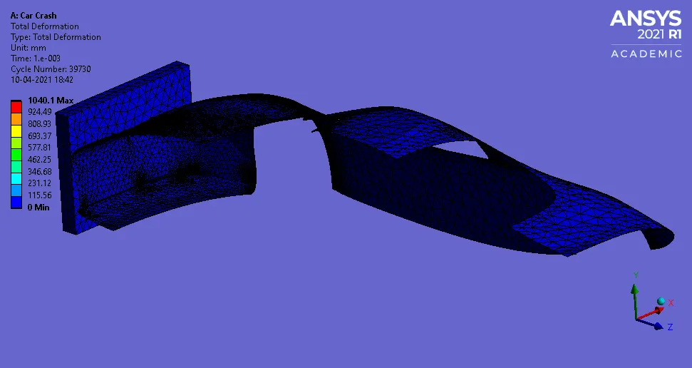
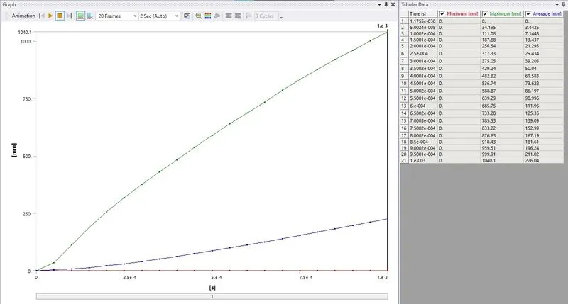
Equivalent Stress
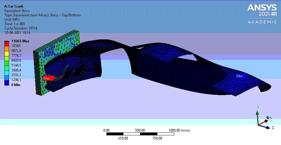
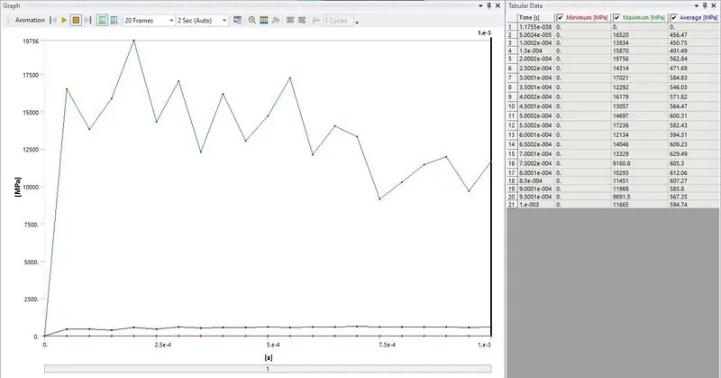
CASE 1: 0.3 mm Car's Body Thickness
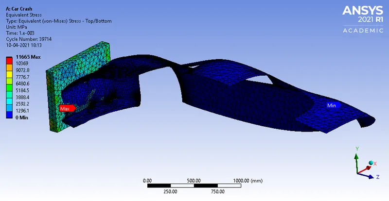
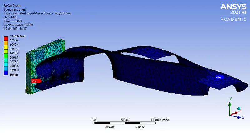
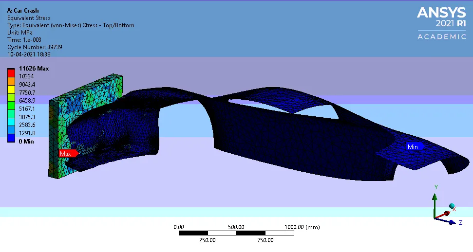
CASE 2: 0.5 mm Car's Body Thickness
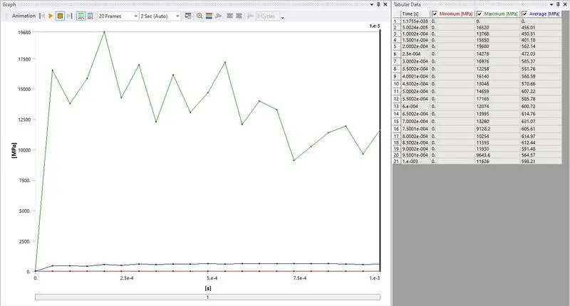
CASE 3: 0.7 mm Car's Body Thickness
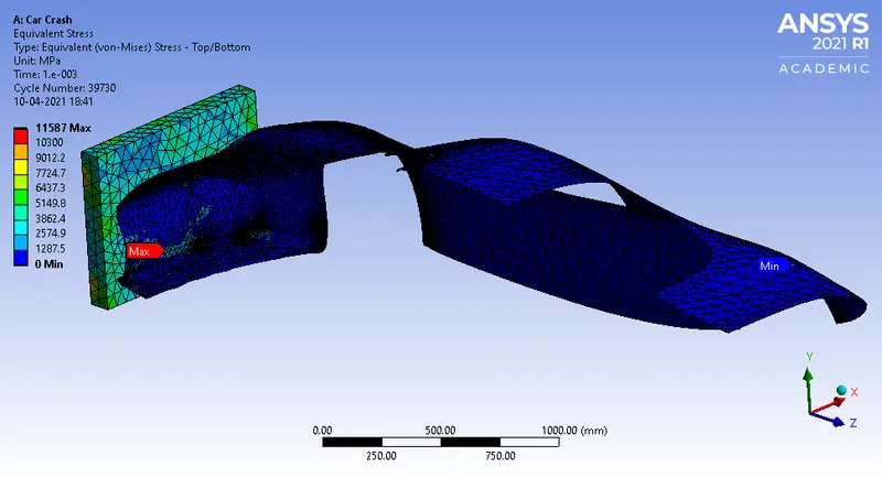
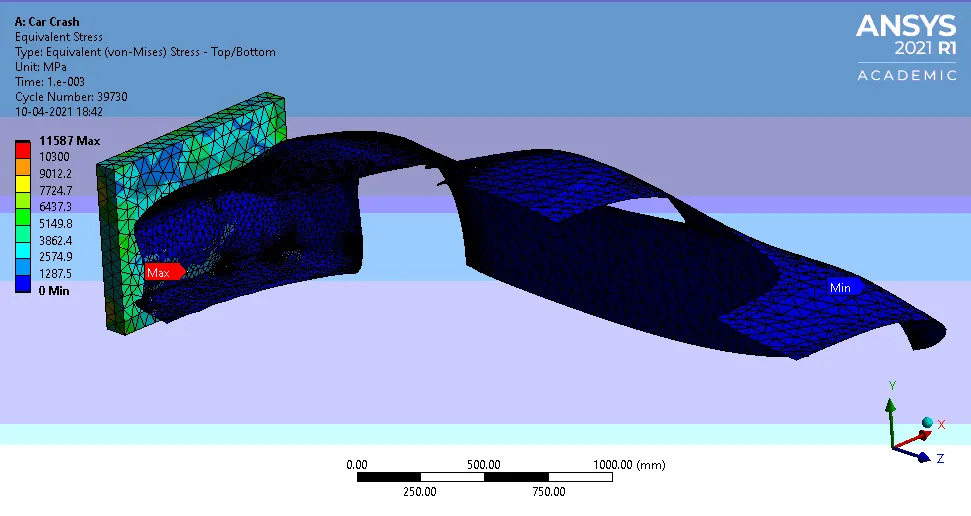
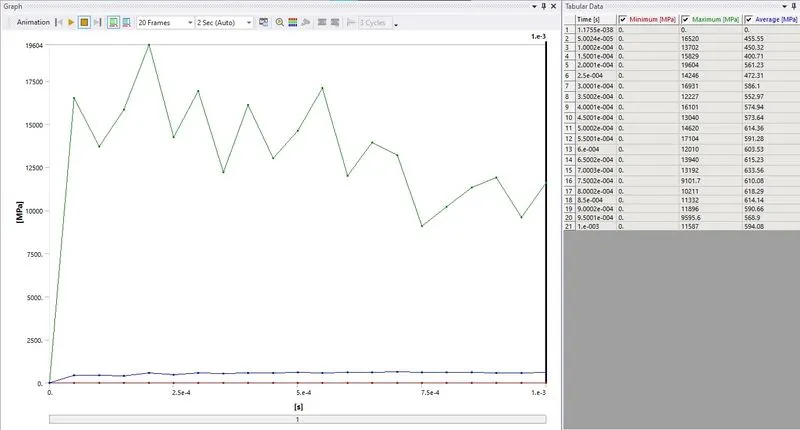
CONCLUSION:
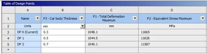
So from the analysis, it can be inferred that with the increase in the thickness of the car's body from 0.3, 0.5 and 0.7, the max total deformation and max equivalent stress experienced is reduced from 1048.1 mm and 11665 MPa, 1044.5 mm and 11626 MPa and 1040.1 mm and 11587 MPa respectively. This suggests with the increase in thickness of the car body the deformation reduces and also the increased thickness develops a resistance to the max equivalent stress for the material Stainless Steel NL.
SIMULATION FILE: "https://drive.google.com/file/d/1WOcvcDXSBYWxYT22yT-Jf1PXIGe7gMrK/view?usp=sharing"