Assembly Workbench
Aim:To design the Parts of quick return mechanism and Cinstant Velocity joint and Assemble all the Chile parts together.
MODEL 1
QUICK RETURN MECHANISM
A quick return mechanism is an apparatus to produce a reciprocating motion in which the time taken for travel in return stroke is less than in the forward stroke. It is driven by a circular motion source (typically a motor of some sort) and uses a system of links with three turning pairs and a sliding pair.
Quick return mechanisms are found throughout the engineering industry in different machines:
- Shaper
- Screw Press
- Power-driven Saw
- Mechanical actuater
- Revolver mechanisms
Design of Quick return Mechanism:
The disc influences the force of the arm, which makes up the frame of resistance of the quick return mechanism. The frame continues to an attached rod, which is connected to the circular disc. Powered by a motor, the disc rotates and the arm follows in the same direction (linear and left-to-right, typically) but at a different speed. When the disc nears a full revolution, the arm reaches its furthest position and returns to its initial position at a quicker rate, hence its name. Throughout the cut, the arm has a constant velocity. Upon returning to its initial position after reaching its maximum horizontal displacement , the arm reaches its highest velocity
The quick return mechanism was modeled after the crank and slider (arm), and this is present in its appearance and function; however, the crank is usually hand powered and the arm has the same rate throughout an entire revolution, whereas the arm of a quick return mechanism returns at a faster rate. The "quick return" allows for the arm to function with less energy during the cut than the initial cycle of the disc.
Quick-return (QR) mechanisms feature different input durations for their working and return strokes. The time ratio (TR) of a QR mechanism is the ratio of the change in input displacement during the working stroke to its change during the return stroke. Several basic types of mechanism have a QR action. These types include slider-crank and four-bar mechanisms. A project on QR mechanism design, within a first course on the theory of mechanisms, has been found to be effective for exposing students to concepts of mechanism design and analysis. This paper reviews basic QR mechanisms, presents a project problem and solution examples, and discusses the value of inclusion of such project problems within theory-of-mechanism courses.Constant velocity joints allows maintaining the same shafts rotation speed.Constant velocity joints facilitate the steering of the vehicle by minimizing the stresses, which would compromise the transmission time.In terms of definition, constant velocity joints are also known with name of homokinetic or CV joints and allow a drive shaft to transmit power through a variable angle. The transmission also happens at constant rotational speed and without any appreciable decrease in play of friction.
Inputs:
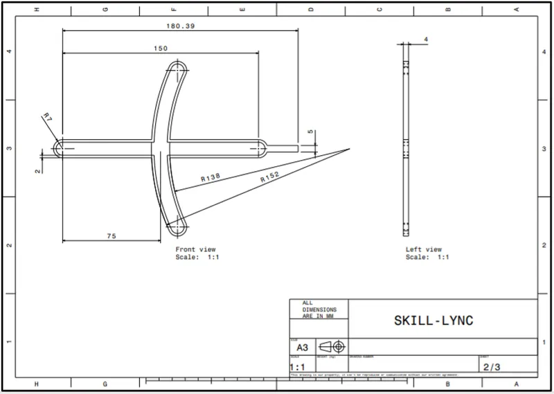
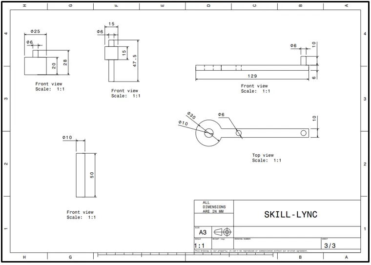
1)Design of Slotted Plate:
- Sketch with Sketch solving Status
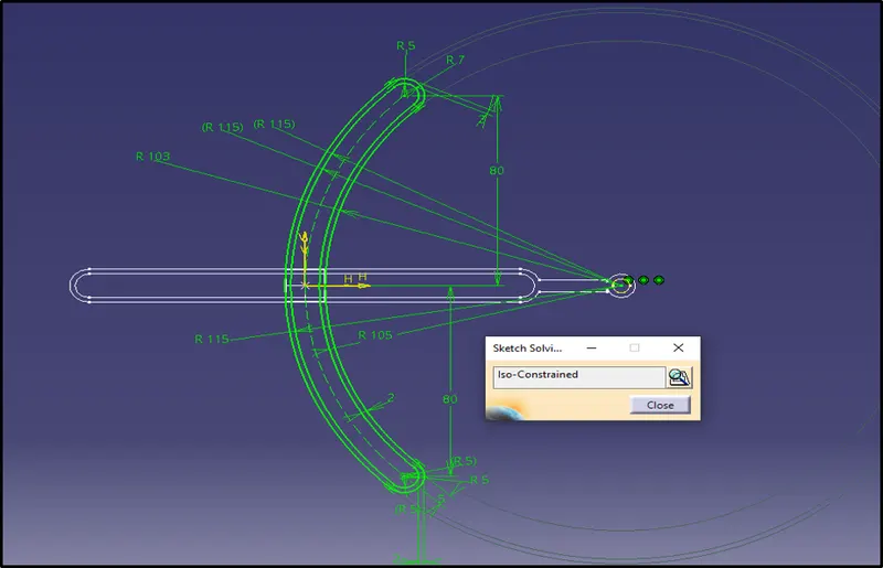
- 3D Modeeling:
1.Go to Part Design
2.Use the pad Command and give the thickness to the Component.
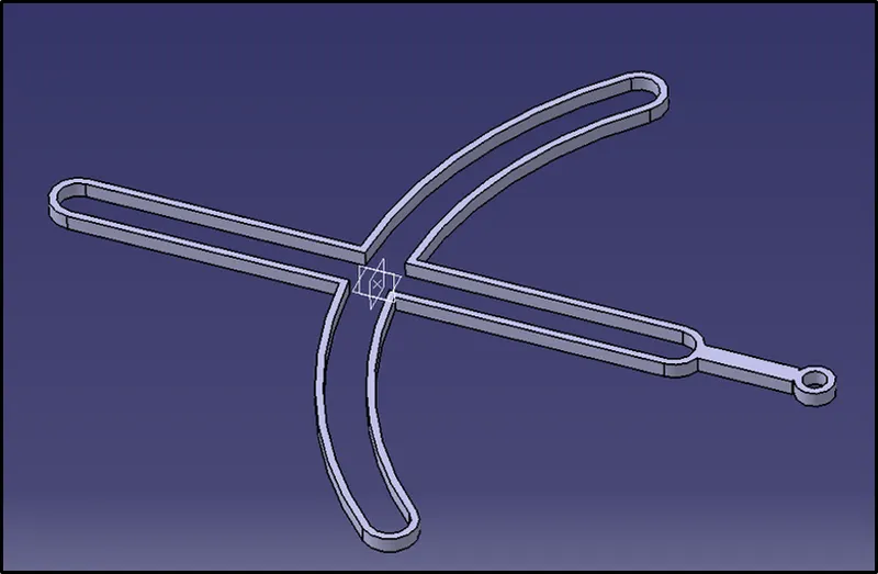
In the similer way we have designed all the individual parts as shown in the figure:
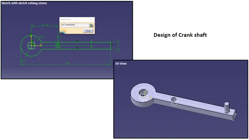
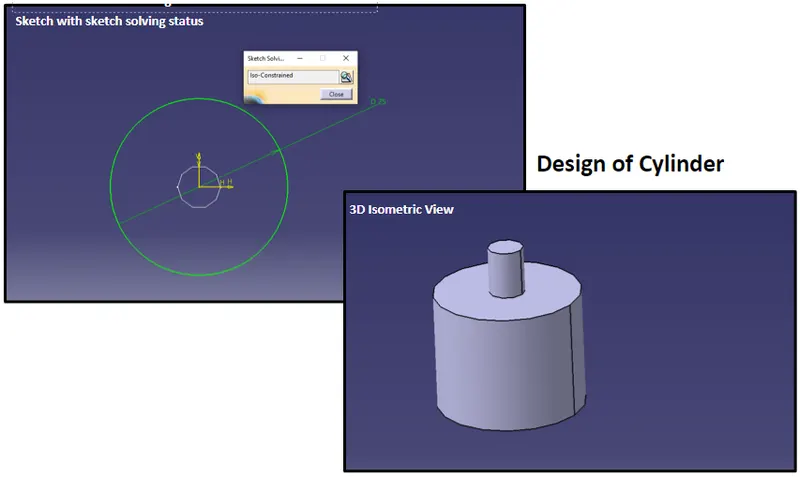
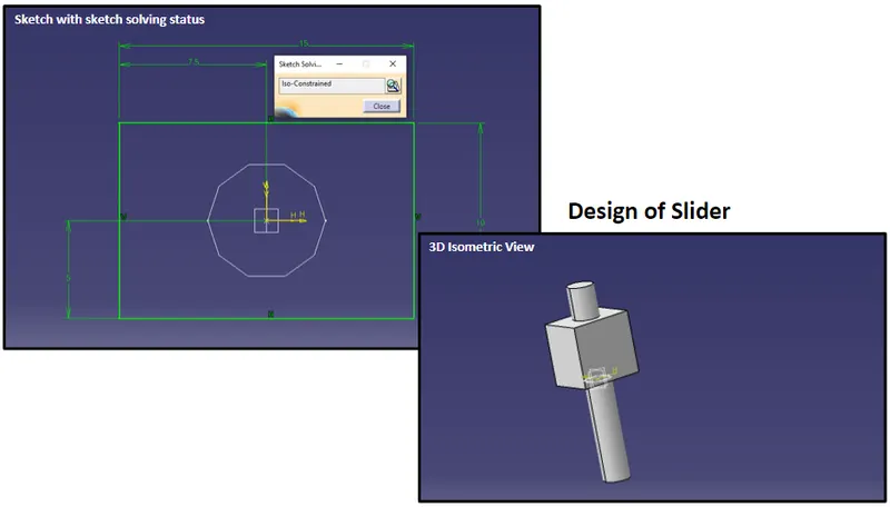
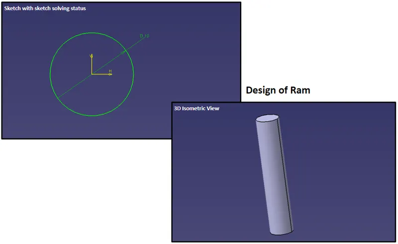
Hence the Design of all the parts of Quick return mechanism are Completed.
Now Lets us move to the Assembly of the All the parts.
- Select the Start -> Mechanical Design -> Assembly Design command to launch the required workbench.
- The workbench is opened. The commands for assembling parts are available in the toolbar to the right of the application window.
- You will notice that "Product1" is displayed in the specification tree, indicating the building block of the assembly to be created.
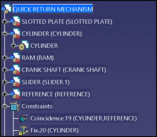
- We will start the scenario with an existing assembly. Product1 is composed of three parts created in the Part Design Workbench:
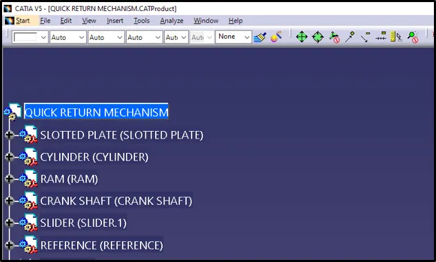
- Surface and Coincidence constraints have been defined for these parts in the Assembly workbench.
Let us start the constraining the component :
- Fixing the Component
This task shows you how to set the first constraint. This operation consists in fixing the position of a component in space so as to use this component as the base of the assembly.
1)Select CYLINDER in the specification tree or in the geometry area.
2)Click the Fix Component  icon in the Constraints toolbar.
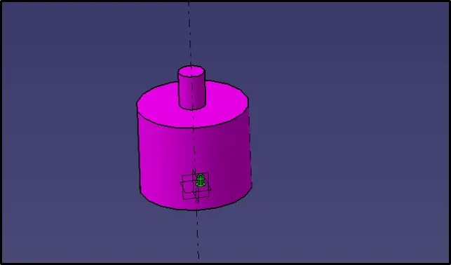
3)The component CYLINDER is immediately fixed. The application indicates this by displaying a green anchor symbol on the component.
- Setting up the constraints between the Component
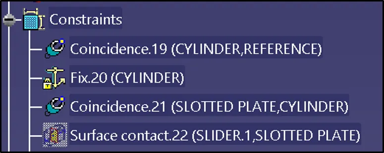
1)This task consists in setting a coincidence constraint, then a contact constraint between the component you have just inserted.
For Example:Constrain between the Cylinder and the Slotted plate as shown in fig below
2)Click the Coincidence icon  .
.
3)Select Axis in the geometry area for which wee need to give the constrain.
4)As the coincidence constraint is created, CYLINDER and SLOTTED PLATE are aligned:
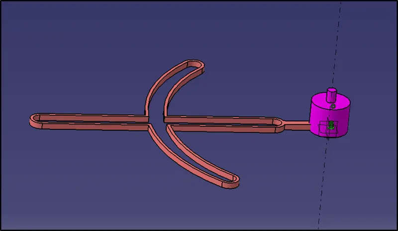
5)Now, you are going to set a contact constraint between CYLINDER and a circular face of SLOTTED PLATE.
- To do so, click the Contact Constraint icon
 .
. - Select the faces between which the constrain has to be created.
- As the contact constraint is created, the slotted plate is located exactly on the cylinder as shown in the figure:
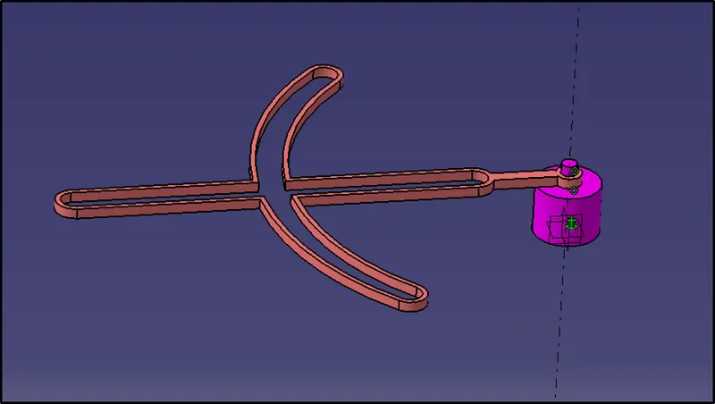
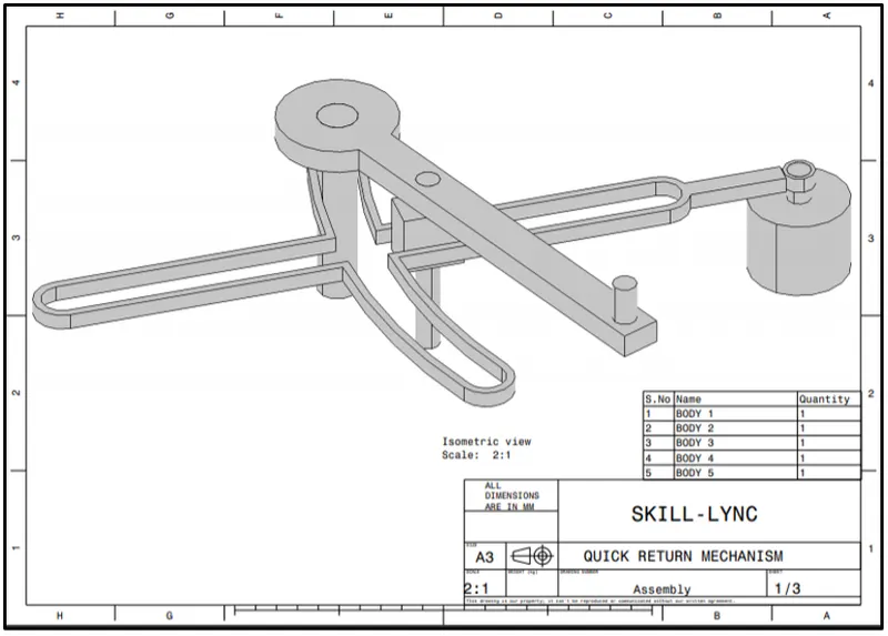
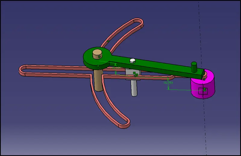
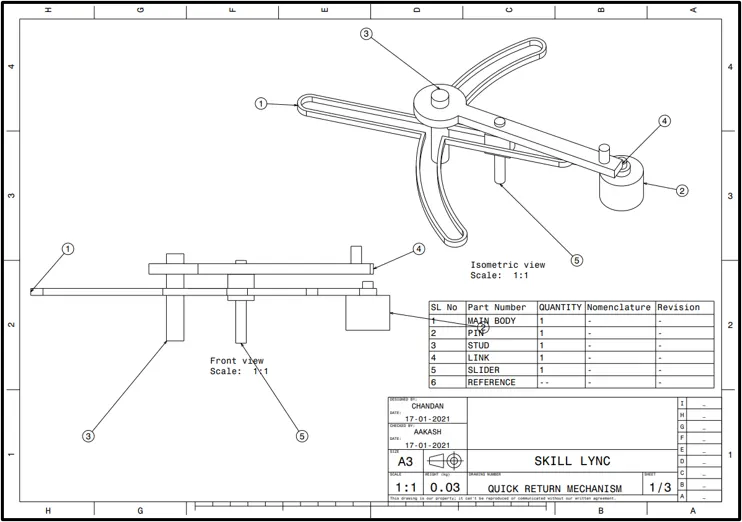
Thus the assembly of Quick return Mechanism now looks like this:
- 2D Drawing
MODEL 2
CONSTANT VELOCITY JOINT
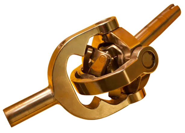
Constant-velocity joints (also known as hCV joints) allow a drive shafts to transmit power through a variable angle, at constant rotational speed, without an appreciable increase in friction or play. They are mainly used in front wheel drive vehicles. Modern rear wgheel drive cars with independent rare suspension typically use CV joints at the ends of the rear axle halfshafts and increasingly use them on the drive shafts.
Constant velocity, or CV, joints are used to connect your vehicle’s transmission to your wheels. CV joints are part of the driveshaft and are used primarily on front-wheel drive vehicles, but they are also used in rear- and four-wheel drive vehicles. Each drive wheel has two CV joints: the inner joint connects the transmission to the axle, and the outer joint connects the axle to the wheel. The CV joint’s name comes from its ability to move with your vehicle’s suspension in any direction (if your vehicle hits a pothole or an uneven surface) and still be able to keep the drive wheels moving at a constant velocity. The CV joint is a very special joint: it connects two different rotating shafts. These two rotating shafts are stuck in a fixed position; so, the CV joint must be able to move and bend to keep these two shafts connected. CV joints are being used in newer vehicles and are taking the place of the old “U” joints. The CV joint is able to transmit even levels of torque to the wheels continually no matter what angle it’ in. This means that no matter how many potholes you hit, or if the vehicle is turning, the CV joint will keep the drive wheels moving at a constant velocity.
Inputs:
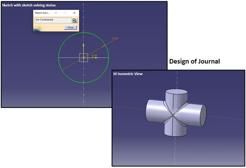
Design of Journal
- Inputs
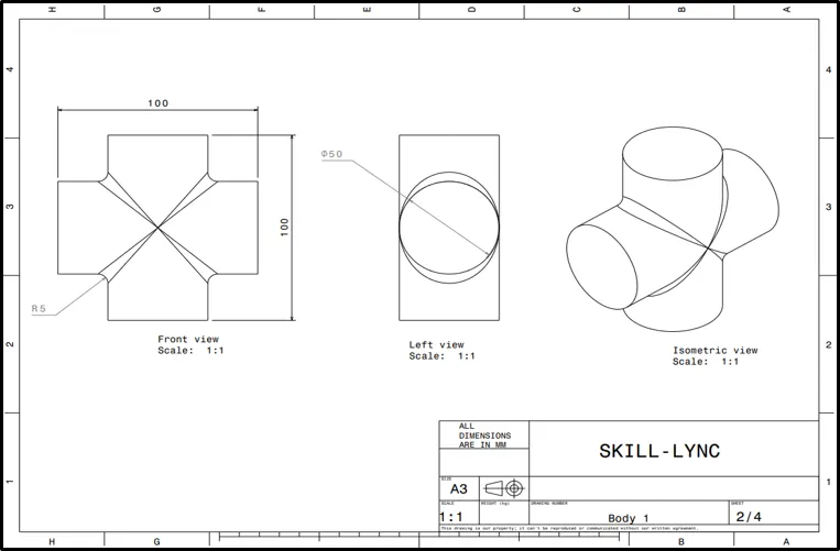
- Output
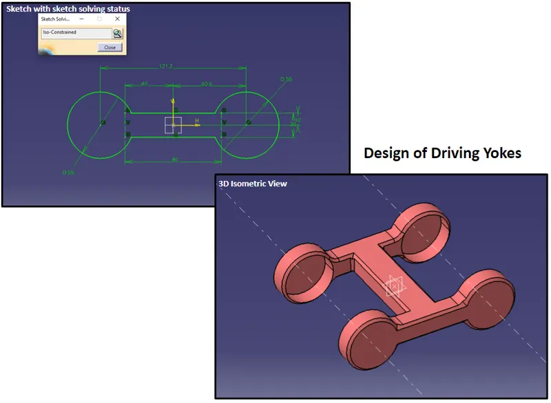
Design of Driving Yoke
- Input:
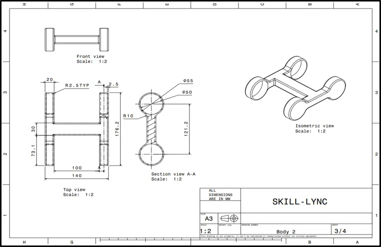
- Output:
Design of Driving Yoke
- Input:
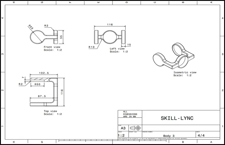
- Output:
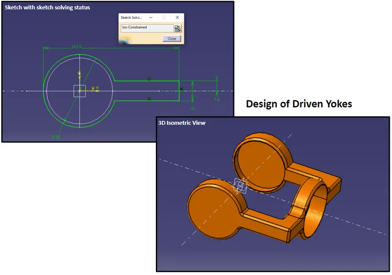
Hence the Design of all the parts of CV JOINTS are Completed.
Now Lets us move to the Assembly of the All the parts.
- Select the Start -> Mechanical Design -> Assembly Design command to launch the required workbench.
- The workbench is opened. The commands for assembling parts are available in the toolbar to the right of the application window.
- You will notice that "Product1" is displayed in the specification tree, indicating the building block of the assembly to be created.
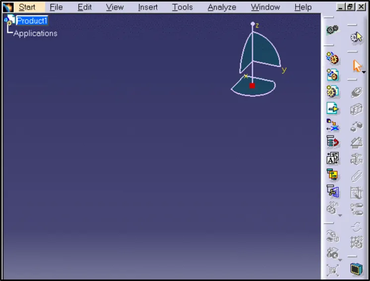
- We will start the scenario with an existing assembly. Product1 is composed of three parts created in the Part Design Workbench:
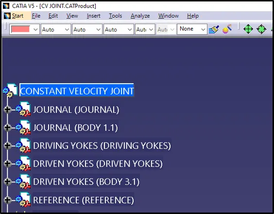
- Surface and Coincidence constraints have been defined for these parts in the Assembly workbench.
Let us start the constraining the component :
- Fixing the Component
This task shows you how to set the first constraint. This operation consists in fixing the position of a component in space so as to use this component as the base of the assembly.
1)Select DRIVING YOKES in the specification tree or in the geometry area.
2)Click the Fix Component icon in the Constraints toolbar.
3)The component DRIVING YOKES is immediately fixed. The application indicates this by displaying a green anchor symbol on the component.
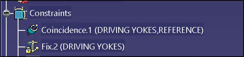
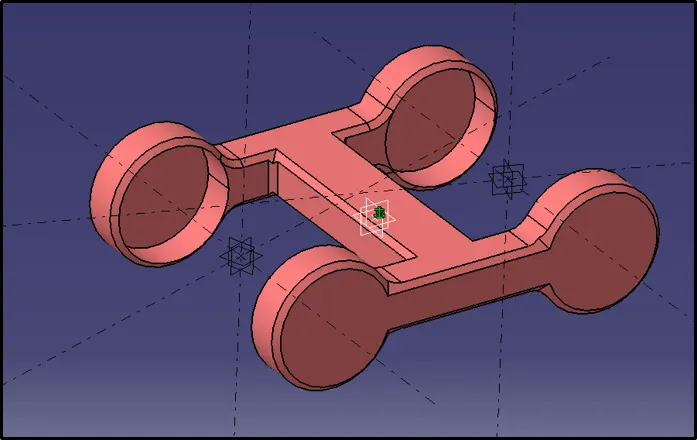
- Setting up the constraints between the Component
1)This task consists in setting a coincidence constraint, then a contact constraint between the component you have just inserted.
For Example:Constrain between the DRIVING YOKES and the JOURNAL as shown in fig below
2)Click the Coincidence icon .
3)Select Axis in the geometry area for which wee need to give the constrain.
4)As the coincidence constraint is created, JOURNAL and DRIVING YOKES are aligned:
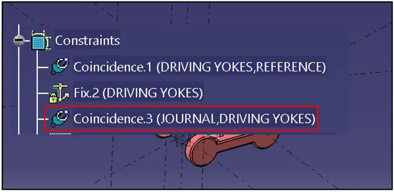
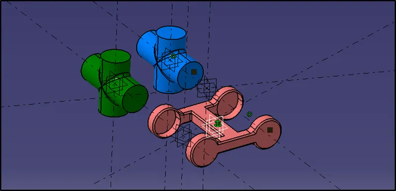
5)Now, you are going to set a contact constraint between JOURNAL and DRIVING YOKES.
- To do so, click the Contact Constraint icon.
- Select the faces between which the constrain has to be created.
- As the contact constraint is created, the JOURNAL is located exactly inside the DRIVING YOKES as shown in the figure:
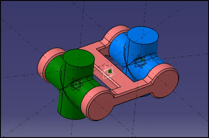
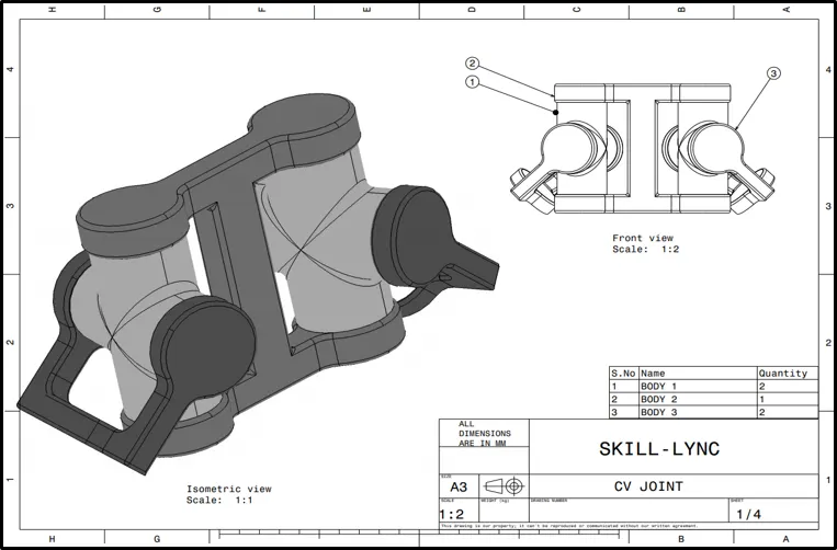
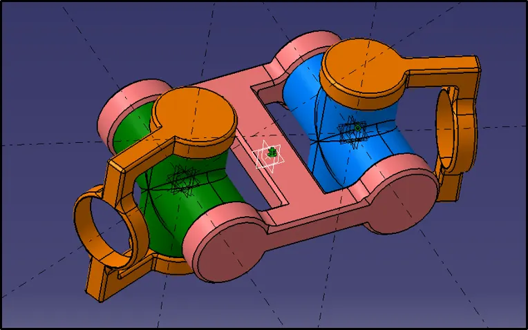
Thus the assembly of CV JOINTS now looks like this:
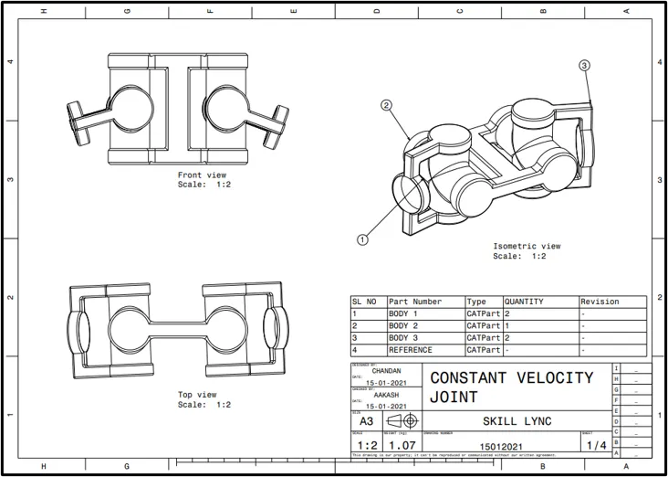
- 2D Drawing
CONCLUSION:
Thus the Given Quick return mechnaism and CV Joints Models are designed and as required and also Drawn the 2D of the bothe the Models in CATIA V5 and studied the mechanism.