2D Meshing of the Automotive Tyre Boot Floor Panel using Hypermesh workbench.
AIM : Mesh the floor panel and assign thickness .
OBJECTIVE :
Clean the geometrical error and fix or remove the deformation in the model.
Extract the mid surface from the model ( manual mid surface )
Give the proper quality criteria
check for the features were minimum length will fail, and make changes according to criteria
Mesh the component with given element size and remove all the quality errors with proper feature capturing
Assign the thickness to all the features accordingly.
PROCEDURE :
Step 1: Import the geometry.
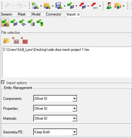
To import the geometry go into Import option, in import option click on import model, select the model to import and then click on import. (If model is not visible, on keyboard press "F" so that the model will be visible on the screen)
Refer the Figure 1 below.
{ Figure 1 }
Step 2 : Criteria for the given model.
Check for the given criteria.
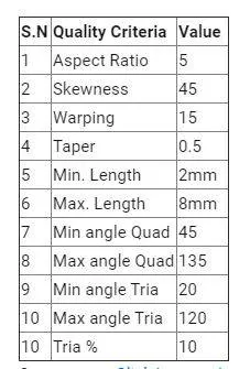
To set the given criteria, Go into Preferences > criteria file setting > Fill the value according to the given criteria as shown in the Figure 2 below.
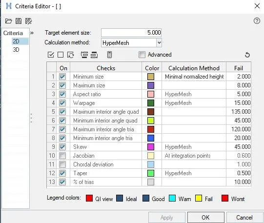
( Figure 2 )
Step 3 : Inspection of the Model .
Check the model through out, check for the features check for small component. Inspection is important for a model because there might be some defects or some error while importing the model. Secoundly inpection is done so that one can know which are the complicated parts or features inthe model. By inspecting we can decide where to start from, which area may take a lot time to clean up.
We can get good view of the component in the topo mode.In topo mode basically we can clearly see the surface, such as we can see the free edge in red, two surfaces connected with each other with a green line and if three surface sare connected to each other yellow line is visible. (Refer Figure 3 and Figure 4 .) ( Figure 3 is the auto view and Figure 4 is topo view )
To on the topo mode first go to visuallization menu. In visualization menu the view is pre setted on the auto view, just click on the down arrow beside the menu nd change the view to topo view.
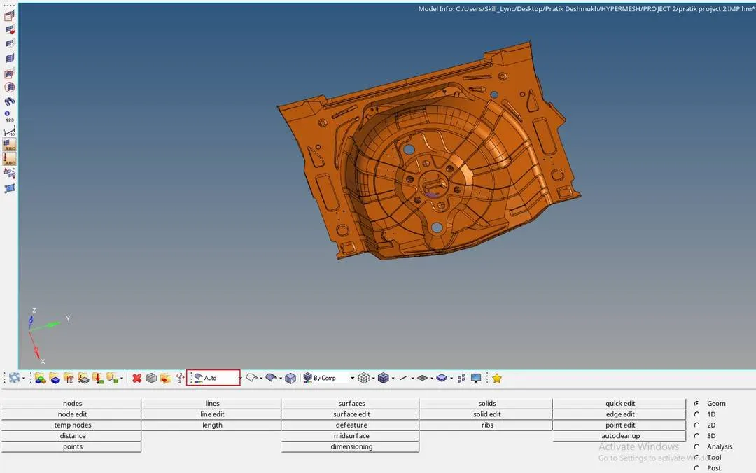
{ Figure 3 }
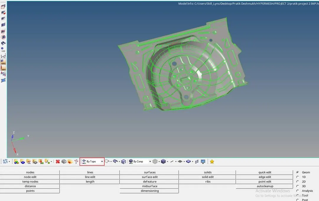
{ Figure 4 }
Step 4 : Cleaning the parent geometry
Cleaning of the parent geometry is very important to get a good midsurface out of it. By cleaning the parent geometry less time is required to clean the mid surface and good feature capturing also can be obtained.
we can remove the unwanted volume component from the geometry as we are working on the mid surface of the main component.
Divide the geometry into certian parts to easy the work of taking out the mid surface. ( we can divide the geometry with various part attached to it ).
Step 5 : Extracting the mid surface form the given component.
Midsurface can be extracted in two ways auto midsurface and maunal mid surface.In auto mid surface there might be some issues in feature capturing and overlapping of surfaces , some complicated surfaces are not extracted in auto mid surface, so to eliminate such issues manual mid surface is prefered.
As there are no complicated surfaces and no ribs attached we can take the mid surface by auto mid .
For that go in geometry > midsurface > click on extraction option > select skin offset. > auto extraction > closed solid > extract. ( refer figure 5 & figure 6 )

{ Figure 5 }

{ Figure 6 }
Step 6: check for the features were minimum length will fail, and make changes according to criteria.
First check the dimension between two nodes of the surface and if the dimension is less or above the criteria the elemenet will fail for the given criteria so to avoid such issues adjust the surface such that it should not fail.
Surface can be adjusted by toogling the line or extending the surfaces kus make sure that features are captured properly.
Do manual clean up
Tools used to manual clean up.
geometry > quick edit > toggle ( toggle is used to remove unwanted point)
geometry > quick edit > replace point ( to replace the unwanted points and lines, it is used to combine the geometry)
geometry >quick edit>add or remove point( to remove the unwanted point)

Step 7: Meshing the component.
Perform meshing : We should mesh the complex surfaces first in order to maintain the proper mesh flow and make meshing easier. While meshing the midsurface we should make make sure that we maintain the trias percentage as low as possible. While meshing curved or complex surface if the mesh doesnot properly catch the surface then we should increase or decrease the node count so that mesh attaches the surface properly.
To mesh click on 2D > automesh > select size abd bias > input given target element size > mixed element > mesh (refer Figure 7 )
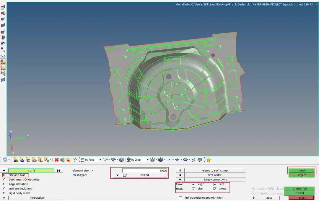
{ Figure 7 }
Refer figure 8 to understand how meshing is conducted.
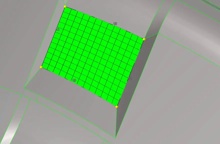
{ Figure 8 }
This is how it will look after whole component is meshed properly ( Refer figure 9 )
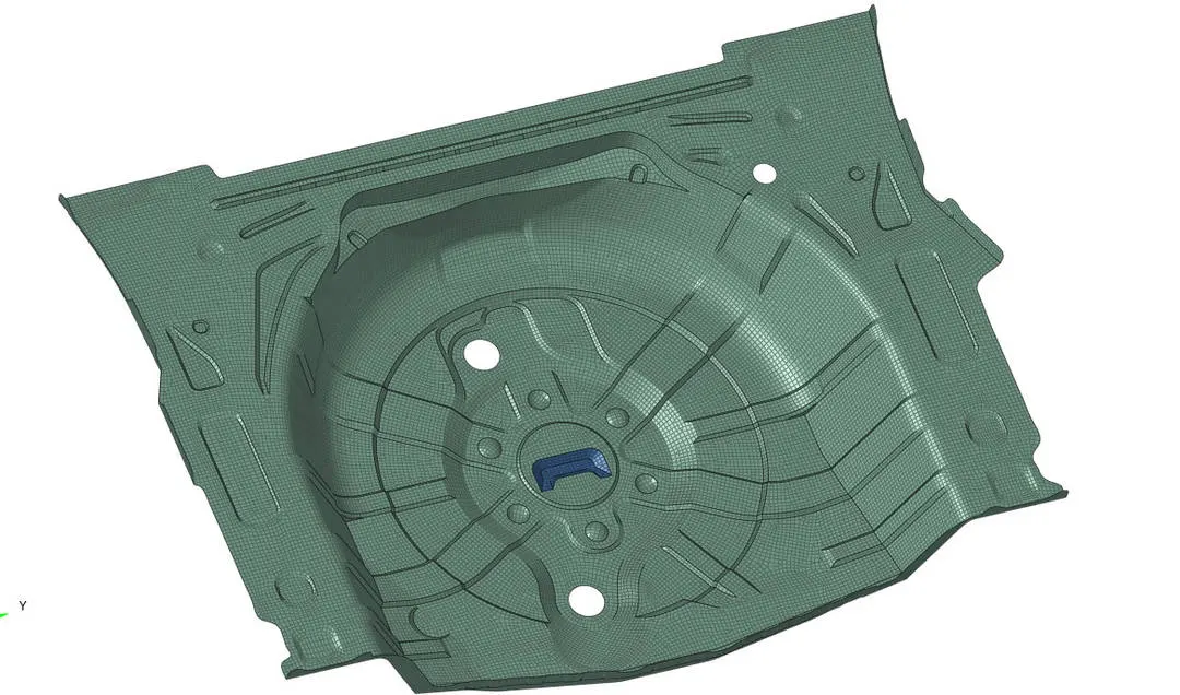
{ Figure 9 }
Step 8: Check for the failing element in quality criteria & Fixing the failed element.
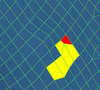
- The failed element are highlighted in yellow and red ( Refer Figure 10 )
{ Figure 10 }
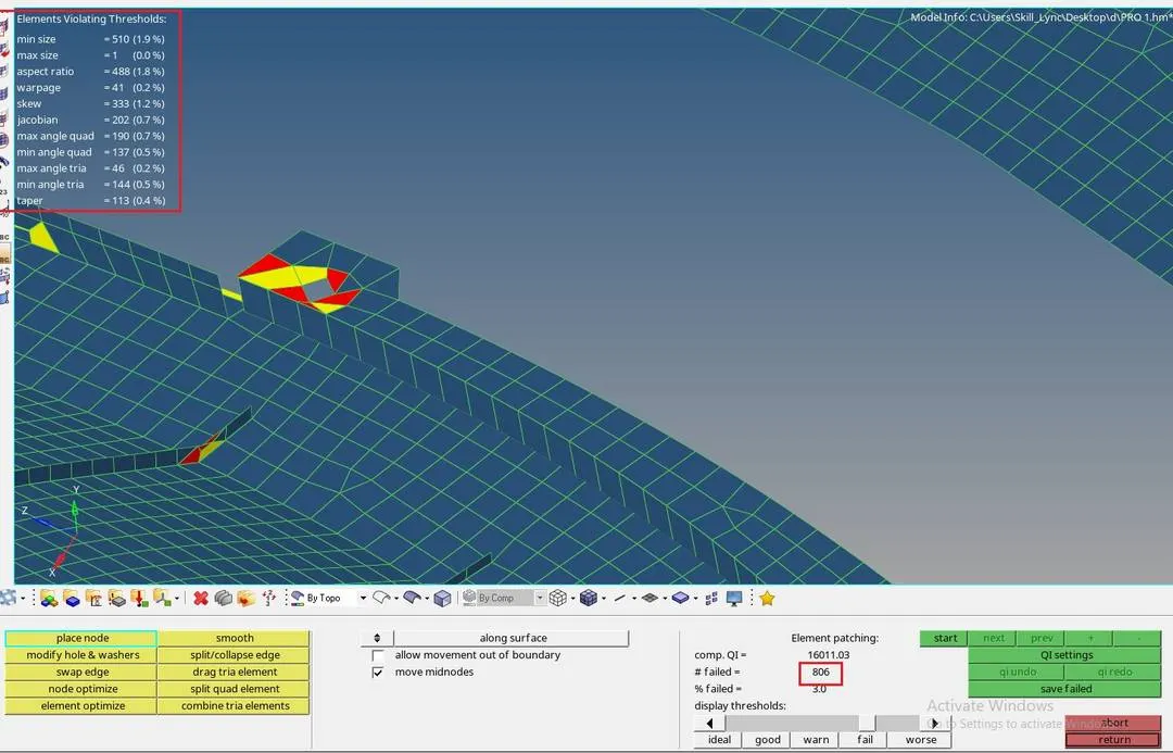
- To check the failed element in mesh click on 2D > quality index
- In quality index you can see total number of elements failing as well as for what criteria they are failing that to you can see as shown in Figure 11
{ Figure 11 }
To remove the element failing as well as decrease the tria concentration
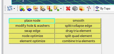
fix the trias and rotating quad. ( Refer Figure 12)
To fix trias and rotating go to 2D > quality index > cleanup tools
place node : node of the element can be dragged
combine tria: two tria can be combined
element optimize: click on the element which are failed it will oplimizes automatically.
smooth : smooth adjust the element size accordingly.
drag tria : you candrag the tria element
{ Figure 12 }
we can also fix the failing element manually by increasing or decreasing the distance or by changing the magnitude
geometry > distance > select the node > give the distance according so that element will not fail. ( refer Figure 13 )

{ Figure 13 }
tools > traslate> select the point and traslate .( refer figure 14 )

{ Figure 14 }
- There may be some other important parameter for tria management.
- No trias in corner or edges.
- No opposite trias.
- No back to back trias.
- No trias in fillet or hemming.
- No rotational quads.
Step 9 : Check for free edges.
There should not be any free edge in the componet as the meshing is then considered as bad mesh because there is no connectivity in the mesh due to free edge.
check for the free edges, to check free edges go to tools > edges > select the component > free edge ( Refer figure 15 )

{ Figure 15 }
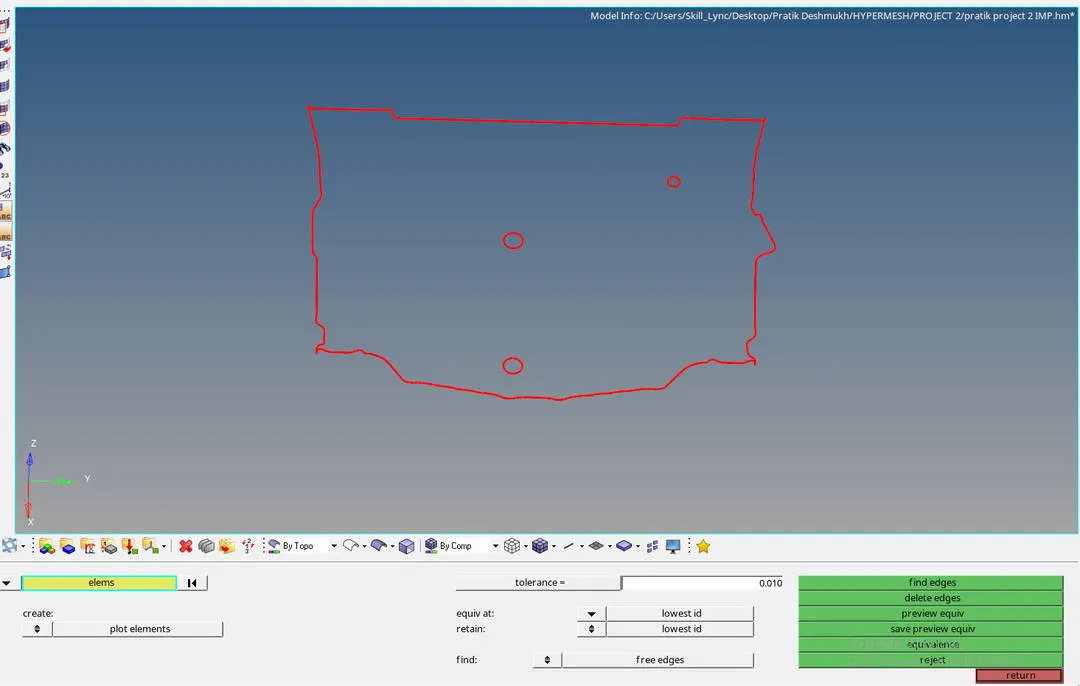
free edges are shown in differenet component and are visible in red as shwon below ( refer figure 16 )
{ Figure 16}
Step 10 : Assign thickness to mesh .
After completion of meshing, now we assign the thickness to midsurface. thickness is assign to mid mesh such that it takes the thickness according to the parent geometry.
For assigning the thickness we create the property and in property we add the thickness value .(refer Figure 17)
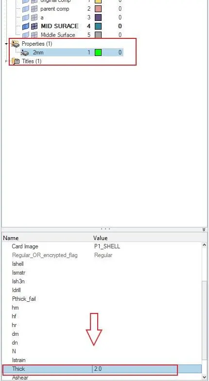
{ Figure 17 }
Now we create a component and in component we add a mesh of different thickness by using tool organize command. ( refer Figure 18 )
create different components accoding to thickness.
Move element to component with respective thickness.
To add the element to that component.
Go to tool > organize > collector > select the element > select desh component part which you make new component > move.
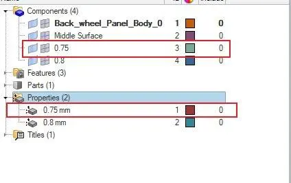
{ Figure 18 }
Assign the property to the component by right clicking on the component and assign ( Refer Figure 19)
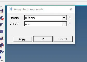
{ Figure 19 }
Image of model after thickness is assigned to it. ( refer Figure 20 )
As you see in figure 20 the colour of the rib will change according to the colour which we have assigned in the component. so by this we can confirm we have created component according to there thickness and when property applied itt will change its thickness accordingly.
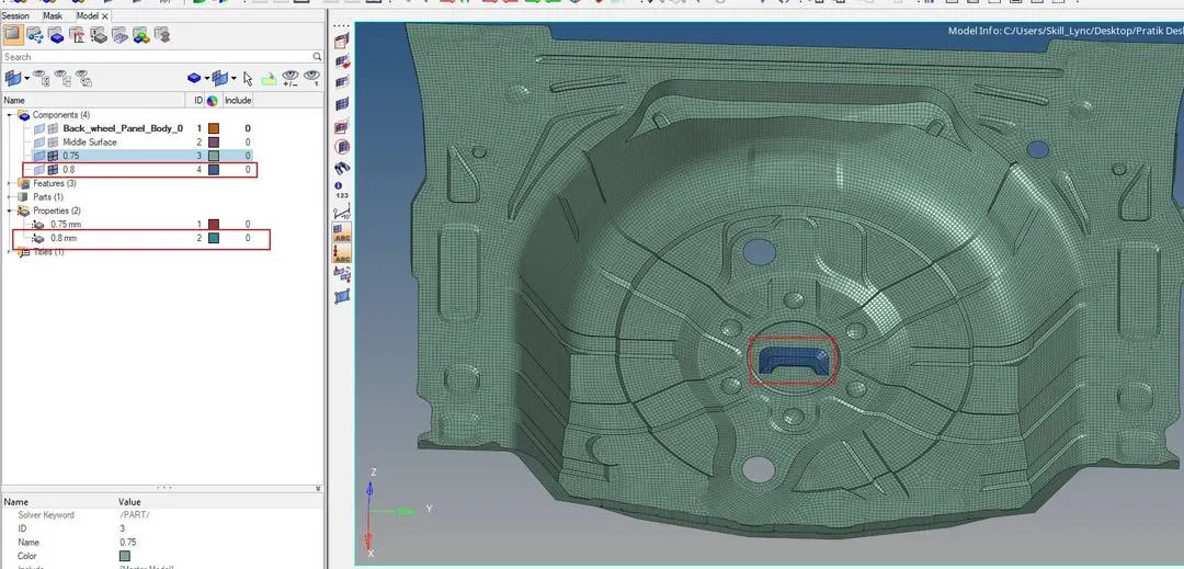
{ Figure 20 }
Image of model after thickness is assigned to it. ( In 2D representation )
To see the model in solid go to 2D detailed element representation tab. ( Refer figure 21 )
{ 2D detailed element representation tab }
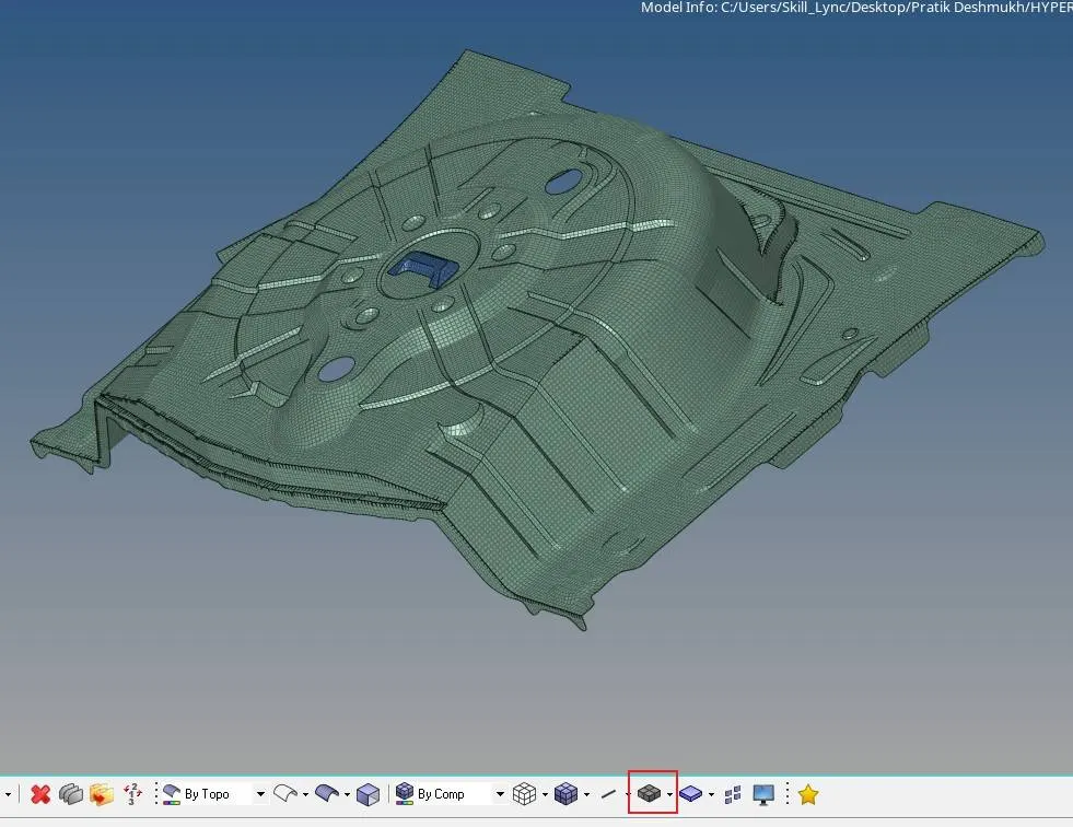
{ Figure 21 }
Final model image :
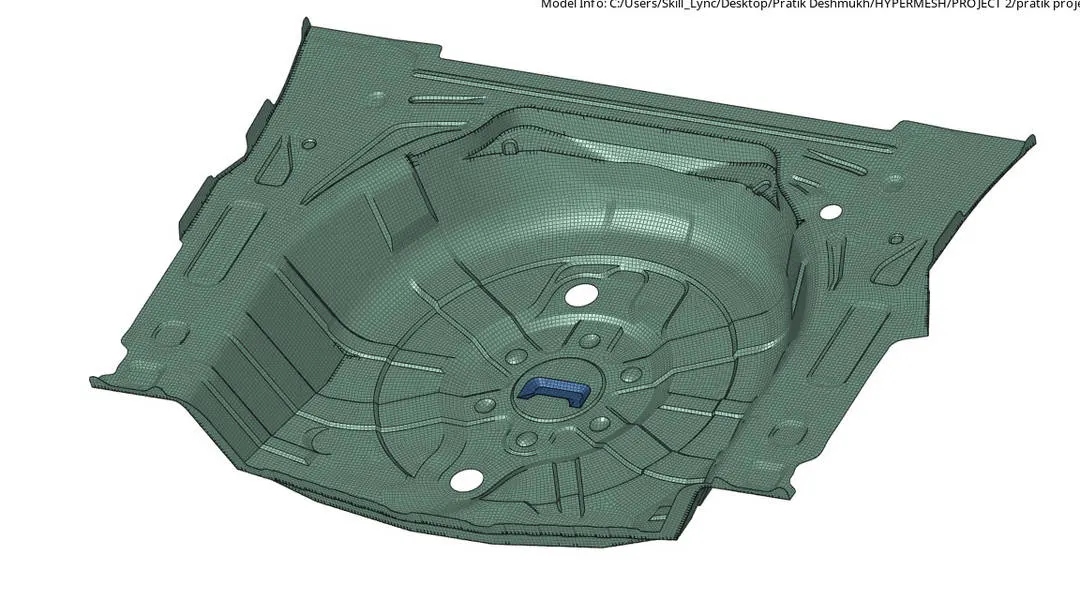
Conclusion : Meshing was done successfully with assigning proper thickness to each and every component.