Extraction of Mid Surface and Meshing of the Car Subparts using Hypermesh Workbench.
Aim : To clean the geometry ,extract the mid surface and then mesh the geometry.
Objective :
- Clean the geometry.
- Extract midsurface.
- Clean midsurface geometry.
- Ignore holes less than dia 5mm.
- Create 2D mesh with target length 5mm, min 3.5mm max 7mm.
- Assign proper thickness, by creating a generic property.
Procedure :
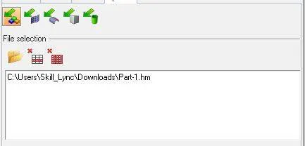
Step 1 : Import the geometry .
Step 2 :There are various issues that are to be fixed before we extract mid surface of the component such as :
- Free edges:
Inspect the model , Check for free edges and duplicate surface and remove the holes below 5 mm.
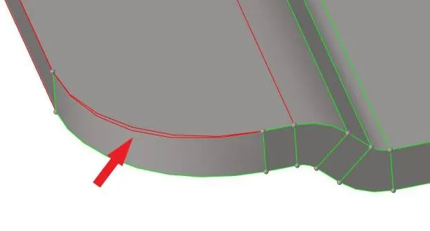
If the surface has free edges we need to toggle the edges or fill the surface accordingly.
To toggle the edges we can use quick edit tab to toggle the edges ( toggle edges are used when the gap is minimum ).
tools used to manual clean up.
geometry > quick edit > toggle ( toggle is used to remove unwanted point)
geometry > quick edit > replace point ( to replace the unwanted points and lines, it is used to combine the geometry)
geometry >quick edit>add orremove point( to remove the unwanted point)

- Duplicate surface :
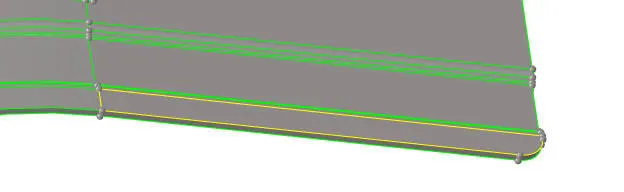
If the surface contain yellow line then mostly the surfaces are overlapped on each other, so delete the surface that is overlapped . (refer fig below)
- Missing surface :
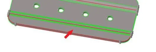
In some cases the surface get deleted. so fill the surface using geom > surface > ruled option.
Step 3 : To extract the mid surface from the component.
take the mid surface.
To take the mid surface ,Go in geometry then in midsurface and create by clicking extract option and select skin offset,extract the mid surface.

Step 4 : Clean the mid surface . carry out the same cleaning which we did on the parent surface.
Fill the holes having diameter 5 and less than 5.
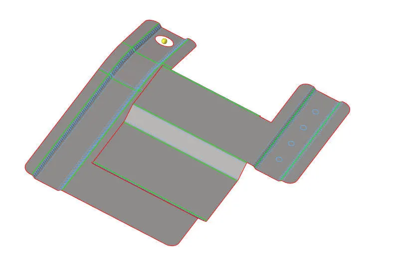
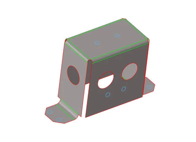
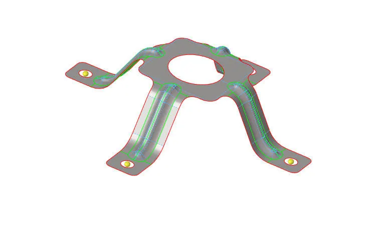
Mid surface for various model :
- Mid surface for Part 1 model :
- Mid surface for Part 2 model :
- Mid surface for Part 3 model :
Step 5 : Meshing .
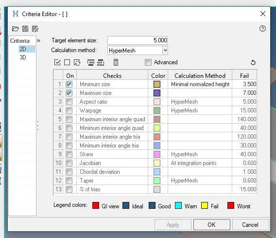
- Before starting the mesh we should fill criteria . To fill the criteria go in preferences criteria file setting and input the criteria given
- Given criteria is target length 5mm, min 3.5mm max 7mm.
-
Perform the mesh.
for mesh go in 2D> automesh > element size > mesh.
- To obtian a better mesh flow , tick the align and size option . ( refer the figure below ). keep element type as mixed and change the element size.

- After meshing some part if we have similar surface we can use position tool to postion the mesh on that surface .
- To position go to Tools > position > select the nodes which element you want to project > select where to project > hit position.

Final meshed component :
- Part 1 model :
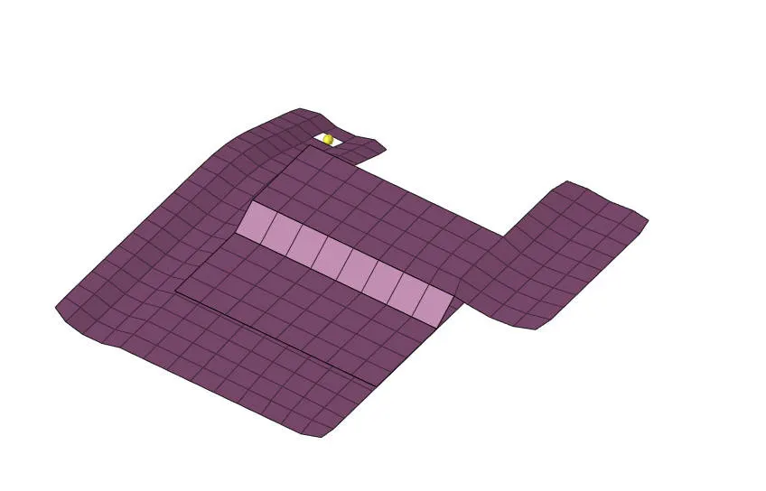
- Part 2 model :
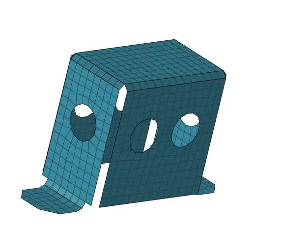
- Part 3 model :
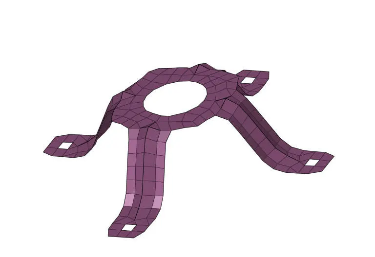
Check for free edges
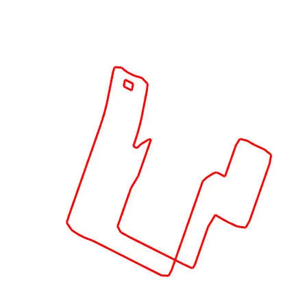
- From free edges we can understand if there is any connectivity in the mesh or not , if there is no connectivity the edge will be shown in red .
- To check free edges go to tools > edges > find edge.
- If the element have lost connectivity click on preview equiv and then equiv .

Free edges :
- Part 1 model :
- Part 2 model :
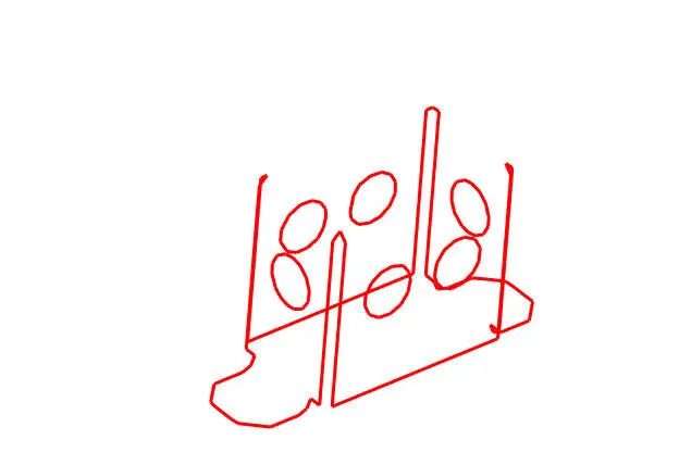
- Part 3 model :
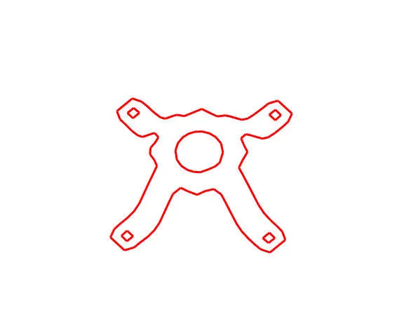
Step 6 : assigning thickness .
- After completion of meshing, now we assign the thickness to midsurface. thickness is assign to mid mesh such that it takes the thickness according to the parent geometry.
- For assigning the thickness we create the property and in property we add the thickness value .
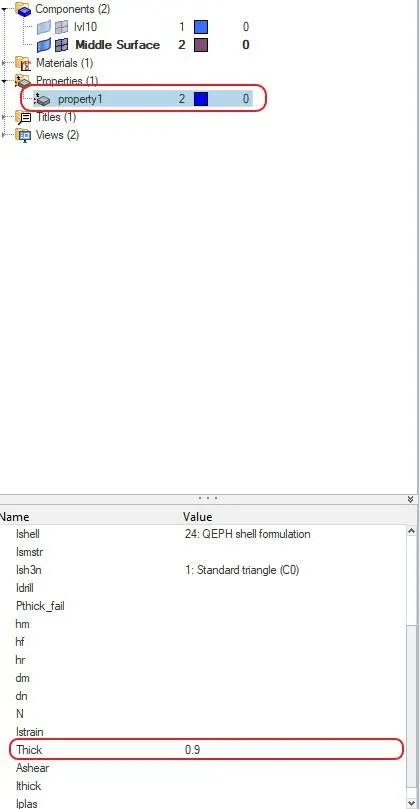
Assign the property to the component by right clicking on the component and assign
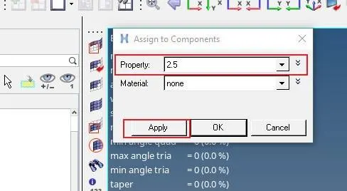
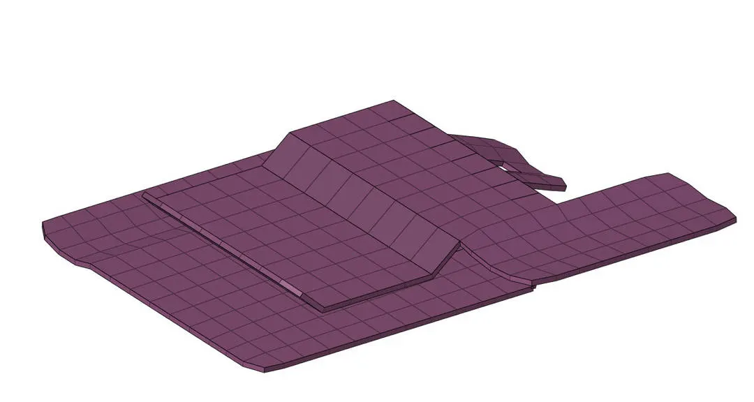
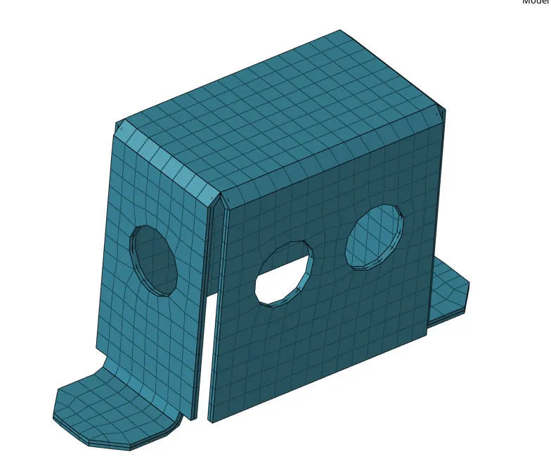
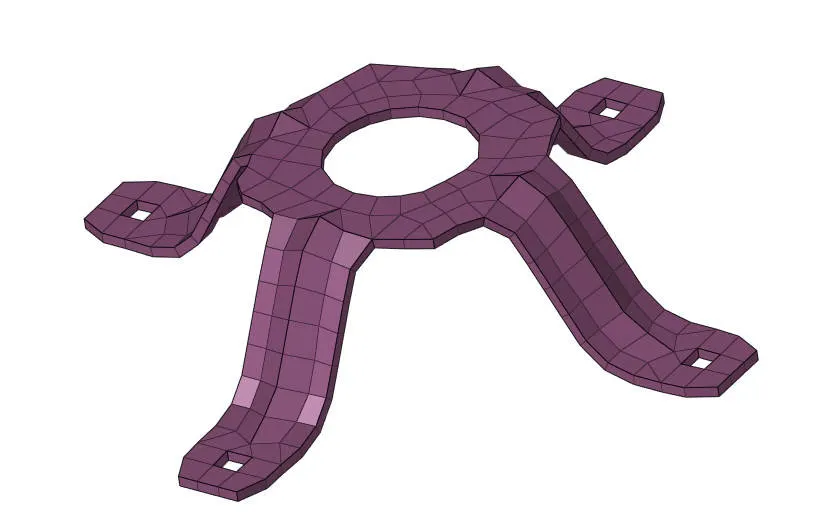
Final model image .
- Part 1 model :
- Part 2 model :
- Part 3 model :
Conclusion : Meshing was done successfully with proper assigning thickness to the component.