Week 11:- 2D Detailing Challenge 2
AIM :
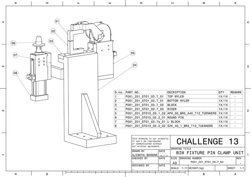
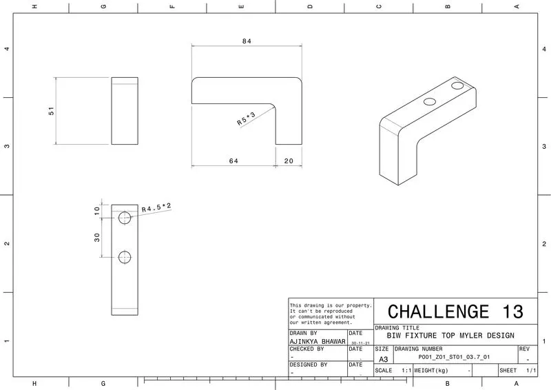
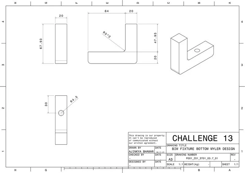
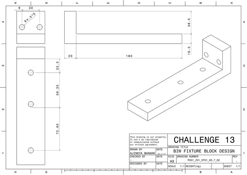
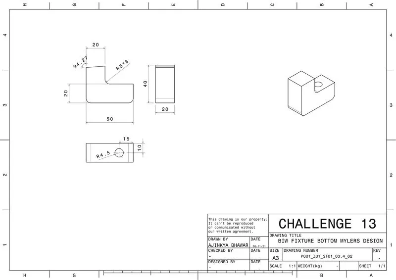
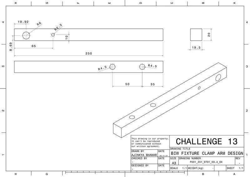
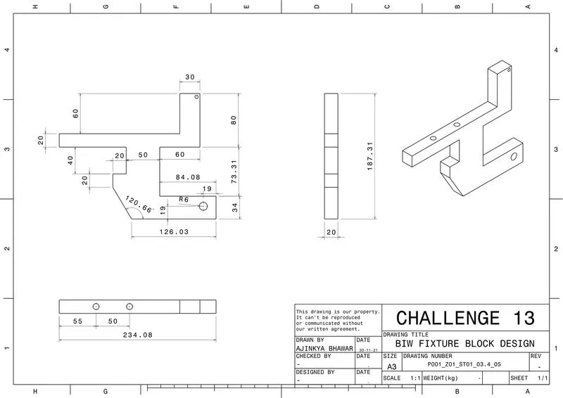
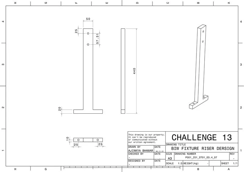
- To Create 2D Drawing for each Clamp Units with all child parts and also create Child pard drawing for the same for the Fixture assembly
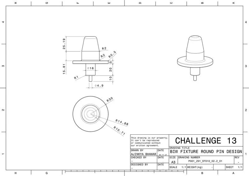
- To Create 2D Drawing for each Pin Units drawings with all child parts and also create Child pard drawing for the same for the Fixture assembly
INTRODUCTION
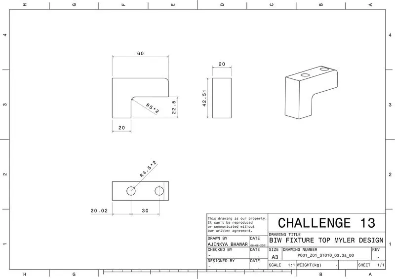
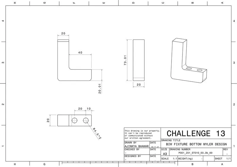
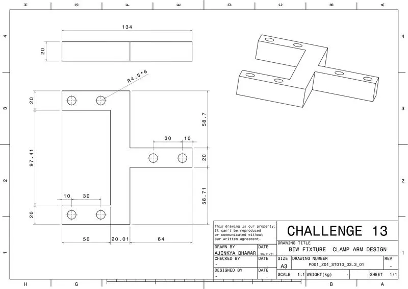
The fixture design after the 3D finishing process has to be done with 2D finishing before it is sent for manufacturing. All the dimensions of the fixture units and their child parts have to clearly mentioned in the drawing sheets. The detailing can be changed as per the requirement of the customer and company standards. GD&T must be used in order to reduce the cost of manufacturing. All the views must be clearly visible and provided with dimensions in the drawing sheets.
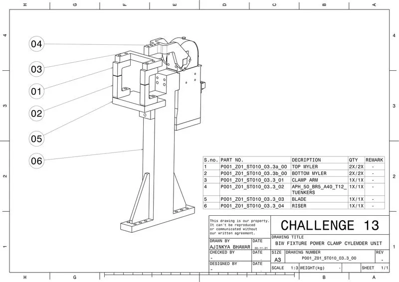
POWER CLAMP CYLINDER UNIT
CLAMP UNIT:
- A clamp unit is a unit designed to clamp/hold the car panel with NC blocks/mylars/rest by using a pneumatic cylinder.
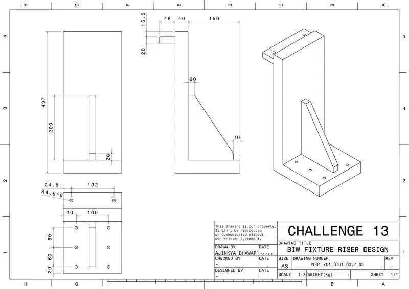
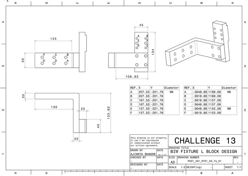
- Clamp arm, finger, Rest/backup, L-block, shims, riser, pneumatic cylinders are the typical parts of clamp unit.
- Clamping force should be considered while designing a clamp unit
REST UNIT:
- A rest unit is used to support the car panel, Also it resists the clamping force of the finger with the help of rest mylars & thus clamps the car panel.
- Rest unit consists of rest mylars, shim packs, riser.
- Holding force should be considered while designing a rest unit.
- Mostly to avoid excess part, to reduce the weight & to reduce the cost of the fixture the rest unit is combined with the clamp unit.
PURPOSE OF CLAMP & REST UNIT:
- The purpose of clamping tools is to securely hold the workpiece in position without obstructing the production process.
- High clamping forces combined with compact dimensions are therefore the most important requirements for a clamping tool. For this reason, clamps are also equipped with mechanical transmission gear units.
3-2-1 Principle Achieved by Clamping & Resting :
- The best & most cost-effective method of part location is referred to as the 3-2-1 method.
- Fixtures work on of 3-2-1 principle.
- (3) Minimum: Three locator blocks to establish the part plane. Three locators or supports are placed under the workpiece. Three locators are usually positioned at the primary locating surface.
- This restricts two axial movements downward & upward and four radial movements. Together, the three locators restrict six degrees of freedom.
Figure - showing the 3-2-1 method achieved by clamping & resting
Hereby using the 3-2-1 method, by introducing a minimum of 3 clamping & 3 resting blocks will restrict 6 degrees of freedom (DOF) [Two axial movements & four radial movement].
CLAMPING: The process of holding the position of the workpiece in the jig or fixture is called clamping. The primary devices used for holding a workpiece are clamps/Clamp unit.
- Clamping force.
- Holding force.
Clamping force is not the same as holding force
1 | Clamping force:
Clamping force signifies the force applied to the workpiece by the drive mechanism via the clamp arm during gripping or clamping operations.
2 | Holding force:
- Holding force, on the other hand, denotes the maximum force, after locking the knee-lever (over-centre position), that can be applied by the workpiece on the gripper/clamp arm without destroying the mechanism.
- Therefore, particular attention must be paid to the maximum holding force when, for example during the production process (welding, bonding), there is a possibility of distortion of the component or if the clamp arm is used as a fixed stop.
- If the holding force specified in the technical details is exceeded, this will inevitably result in the destruction of the mechanism, the clamp arm or the bearing position.
APH_50_BR5_A40_T12_TUENKERS
- A compact clamp with curve-driven lever mechanism for constant clamping force and tension reverse,
- Enclosed mono-block housing of aluminium material with integrated mechanics and flat cylinder, Sizes 50/63/80,
- Forked clamping arm with standard hole pattern for adapting contour blocks, continuously adjustable opening angle 15°-135°, Pneumatic cushioning for an open position,
- Optional: Weld immune inductive sensing of closed and opened position (T12), Intelligent sensor identifying components and wear (T60), Pneumatic locking of dead centre positions (V+R position) (HD), Hand-applied version.
- Clamp cylinders are bought out parts. Some of the manufacturers are Tunkers, Zytran, Destaco, Festo, Steel smith.
- Clamp cylinders are generally 50, 63 & 80 bore capacity.
- Open up to 135 degrees for horizontal clamp mounting.
- Open up to 105 degrees for vertical clamp mounting.
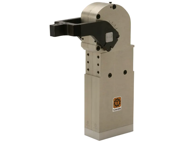
Figure - APH_50_BR5_A40_T12_TUENKERS
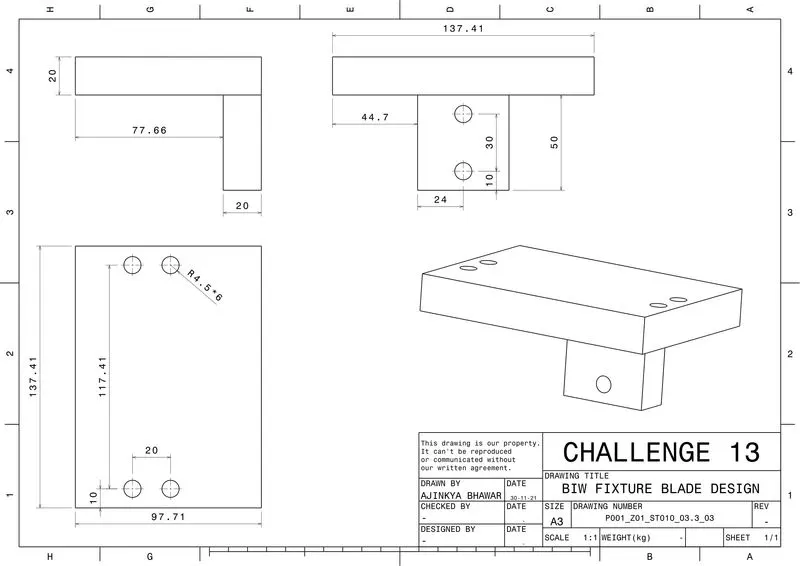
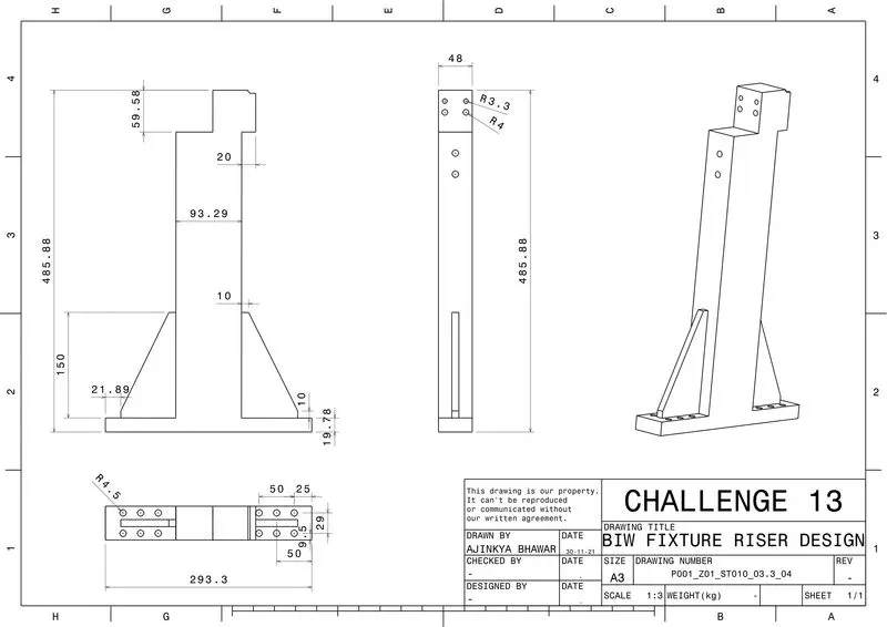
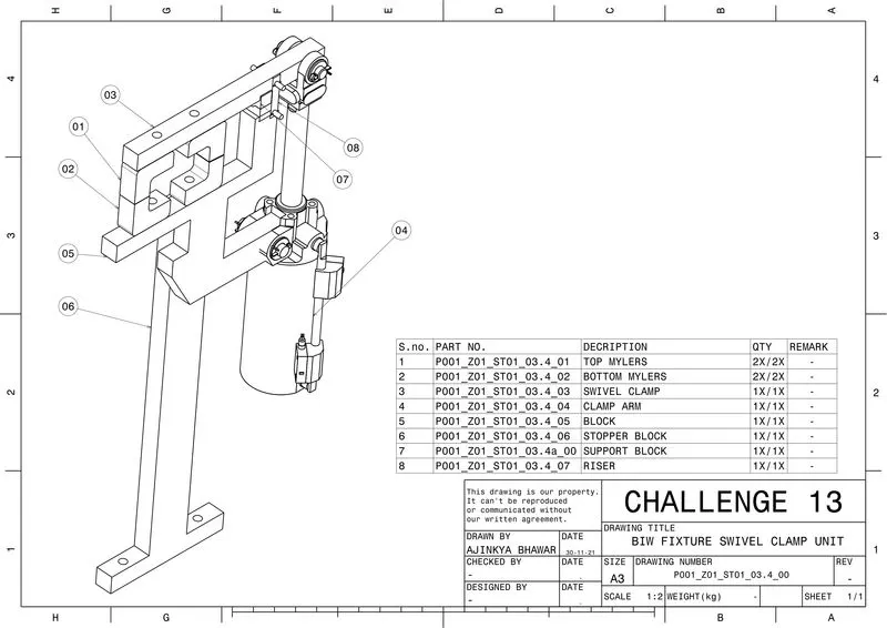
SWIVEL CLAMP UNIT
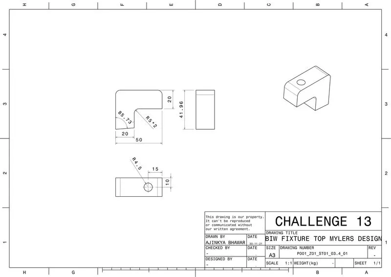
PIN CLAMP UNIT