Week 10 - Simulating Combustion of Natural Gas.
Aim
Part 1: To Perform a combustion simulation on the combustor model and plot the variation of the mass fraction of the different species.
Part 2:To add the water content in the fuel from 5% to 30% by mole and observe the effect of it on the results.
Introduction
Combustion is a chemical process in which a substance reacts rapidly with oxygen and gives off heat. The original substance is called the fuel, and the source of oxygen is called the oxidizer. The fuel can be a solid, liquid, or gas, although for airplane propulsion the fuel is usually a liquid.
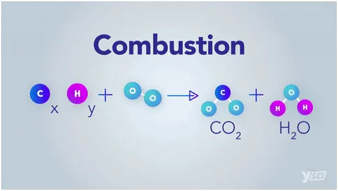
The products of a complete combustion reaction include carbon dioxide (CO2) and water vapor (H2O). The reaction typically gives off heat and light as well. The general equation for a complete combustion reaction is:
Fuel + O2 → CO2 + H2O
In an internal combustion engine (ICE), the ignition and combustion of the fuel occurs within the engine itself. The engine then partially converts the energy from the combustion to work. The engine consists of a fixed cylinder and a moving piston. The expanding combustion gases push the piston, which in turn rotates the crankshaft. Ultimately, through a system of gears in the power train, this motion drives the vehicle’s wheels.
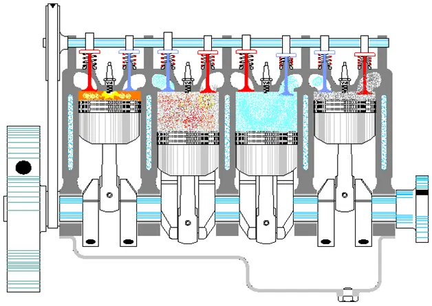
There are two kinds of internal combustion engines currently in production: the spark ignition gasoline engine and the compression ignition diesel engine. Most of these are four-stroke cycle engines, meaning four piston strokes are needed to complete a cycle. The cycle includes four distinct processes: intake, compression, combustion and power stroke, and exhaust.
Spark ignition gasoline and compression ignition diesel engines differ in how they supply and ignite the fuel. In a spark ignition engine, the fuel is mixed with air and then inducted into the cylinder during the intake process. After the piston compresses the fuel-air mixture, the spark ignites it, causing combustion. The expansion of the combustion gases pushes the piston during the power stroke. In a diesel engine, only air is inducted into the engine and then compressed. Diesel engines then spray the fuel into the hot compressed air at a suitable, measured rate, causing it to ignite.
Theory
Chemical kinetics, also known as reaction kinetics, is the branch of physical chemistry that is concerned with understanding the rates of chemical reactions. It is to be contrasted with thermodynamics, which deals with the direction in which a process occurs but in itself tells nothing about its rate. Chemical kinetics includes investigations of how experimental conditions influence the speed of a Chemical reaction and yield information about the reaction's mechanism and transition states, as well as the construction of mathematical models that also can describe the characteristics of a chemical reaction.
Factors affecting reaction rate includes:
- Nature of the reactants
- Physical state
- Surface area of solid state
- Concentration
- Temperature
- Catalysts
- Pressure
- Absorption of light
On burning the fuel Soot particulates and nitrogen oxides (NOX) from diesel engine exhaust have been causing serious problems to human health and the global environment. NO contributes not only to the production of acid rain but also to the production of photochemical smog in a reaction with hydrocarbons while under the influence of sunlight. Fine soot particulates (C8H to C10H), which contain mutagenic hydrocarbons, can easily reach far down into lung tissues when inhaled and therefore have a detrimental impact on human health. Diesel engines are the primary power source of vehicles used in heavy duty applications.
These include two wheelers, buses, large trucks, and inside-highway construction and mining equipment. Furthermore, diesel engines are becoming an increasing part of the light duty vehicle market worldwide. In India, 100% of heavy duty vehicles, 60% of light-duty commercial vehicles and 20% of passenger cars are diesel powered. Diesel exhaust is inherently low in the concentration of CO and unburned HC, for NO and particulate matter are being objectionable to be removed from the exhaust. Since the reduction of both NO and soot particulate emissions to the allowed level cannot be accomplished by engine modifications alone, after-treatment activity for the simultaneous reduction of emissions should be developed.
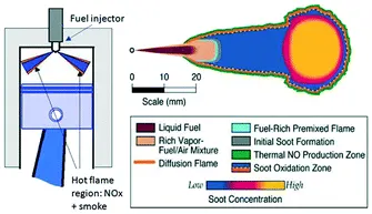
For the emission of the toxic exhaust gas components by engines ,One of the solutions is supplying water into the combustion chambers of engines. stringent emissions regulations for diesel engines requires a way to reduce NOx and soot emissions. Most emissions reduction strategies reduce one pollutant while increasing the other. Water injection is one of the few promising emissions reduction techniques with the potential to simultaneously reduce soot and NOx in diesel engines. While it is widely accepted that water reduces NOx via a thermal effect, the mechanisms behind the reduction of soot are not well understood. The water could reduce the soot via physical, thermal, or chemical effects.
Solving and Modelling
The combustion process invloves the following stages
- Geometry
- Mesh
- Setup
- Solution
- Results
Geometry
Geometry: (Convert 3D to 2D)
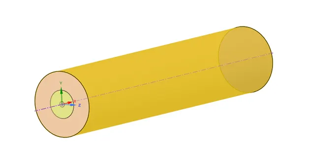
2D GEOMETRY
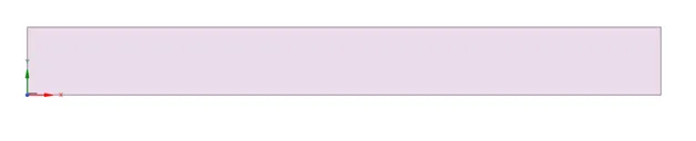
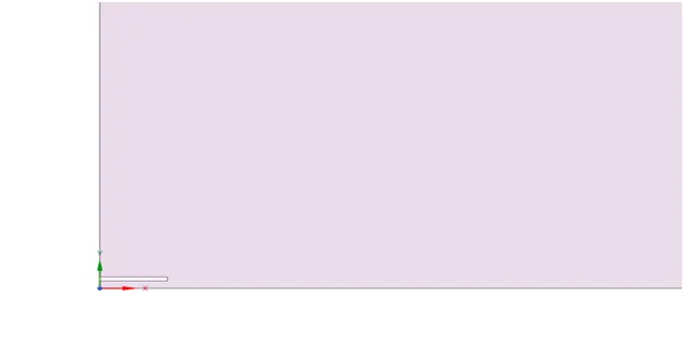
Fuel inlet in 2D geometry
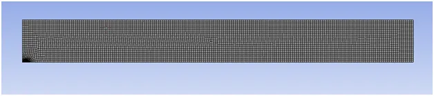
Mesh
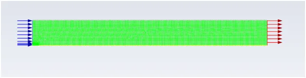
After setup geometry then create the mesh at 4 mm element size
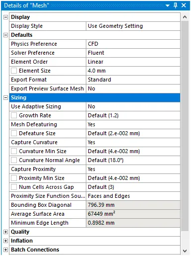
Number of nodes and element are

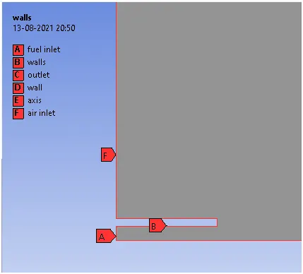
After creating mesh then we have to put name to all boundary of 2D geometry
Which is show in below figure
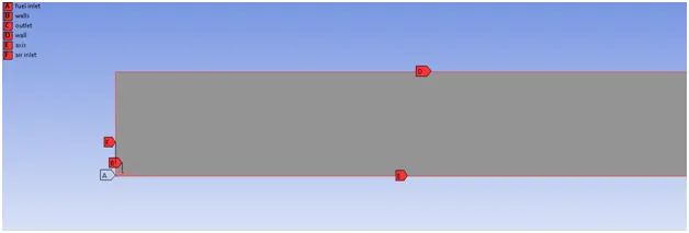
Here A is fuel inlet boundary from where fuel is entered.
Setup
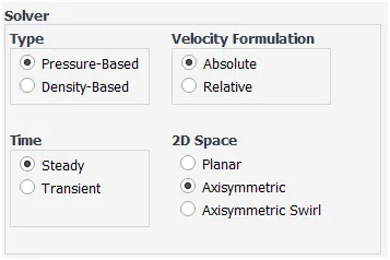
Solver Setting
- Solver Setting K- Epsilon Standard
- Axisymmetic
- Energy Equation on
- Steady State
- Pressure-based solver
- Transport Species with volumetric reaction along with inlet diffusion and Diffusion energy Source turned on.Mixture properties as methane -air 2 and eddy disscipation as turbulence chemistry interaction
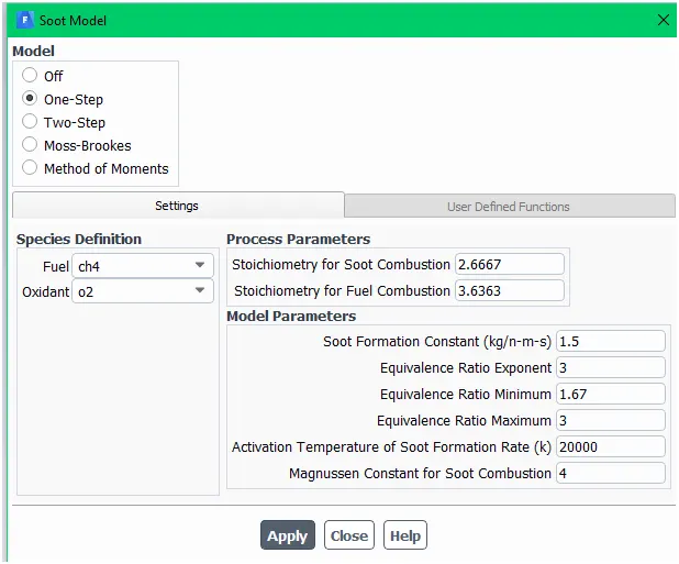
- Turn on Soot and NOx
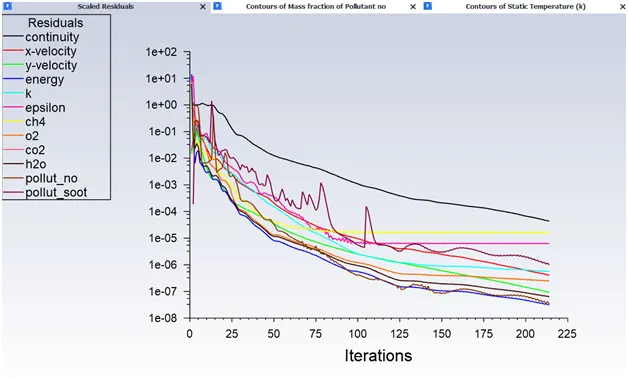
- 600 iteration
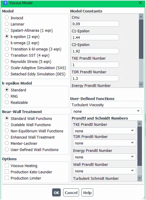
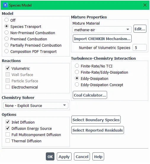
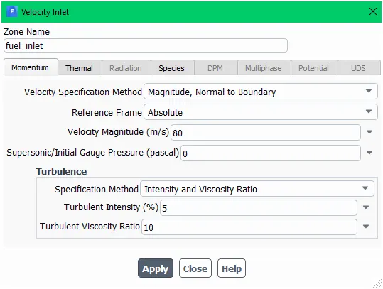
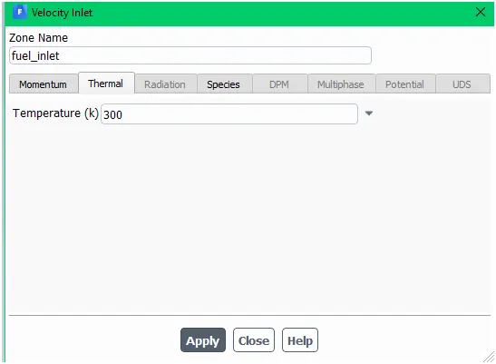
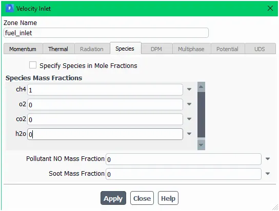
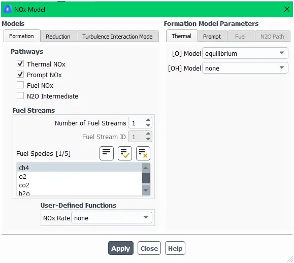
After setup all condition of solver part then calculate for 600 iteration.
Result section
Part I
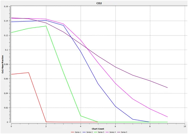
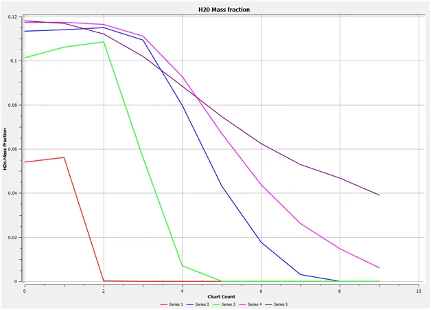
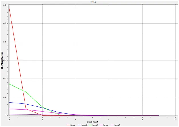
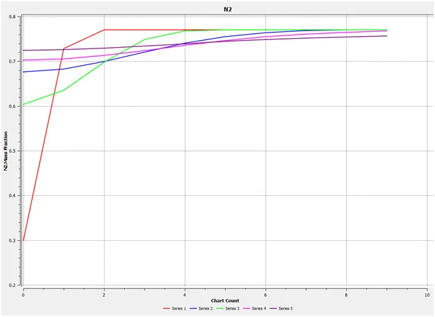
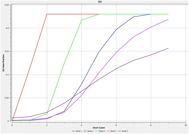
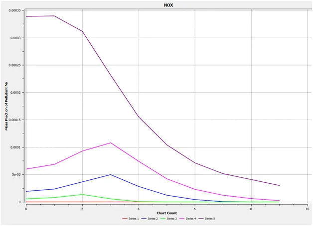
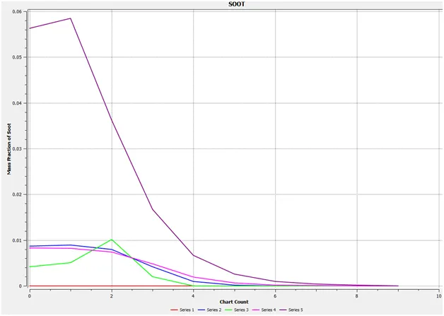
Perform a combustion simulation on the combustor model and plot the variation of the mass fraction of the different species’ in the simulation using line probes at different locations of the combustor as shown in Fig. You need to plot for CO2, H2O, CH4, N2, O2, NOx emissions & Soot formation.
LINE FORMATION ON GEOMETRY

Residual plot:
Mass fraction of CO2

Mass fraction of H2O

Mass fraction of CH4

Mass fraction of N2

Mass fraction of O2

Mass fraction of NOx

Mass fraction of SOOT

Part II
As you must have observed from the above simulation, the Nox and soot is getting formed at the outlet of the combustor. Such formation has harmful effects on the environment and humans. The stringent government norms also demand the least formation of Nox and soot and to satisfy those requirements, you need to check the effect of adding the water in the fuel.
In this part, you need to add the water content in the fuel from 5% to 30% by mole and observe the effect of it on the results. It is necessary to provide line plots and contours to prove your claim.
mass fraction Plots:
Co2 at 5% of water

Co2 at 10% of water

Co2 at 15% of water

Co2 at 20% of water

Co2 at 25% of water

Co2 at 30% of water

H2o at 5% of water

H2o at 10% of water

H2o at 15% of water

H2o at 20% of water

H2o at 25% of water

H2o at 30% of water

Ch4 at 5% of water

Ch4 at 10% of water

Ch4 at 15% of water

Ch4 at 20% of water

Ch4 at 25% of water

Ch4 at 30% of water

N2 at 5% of water

N2 at 10% of water
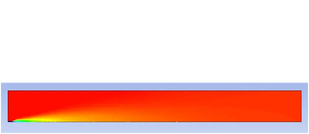
N2 at 15% of water

N2 at 20% of water

N2 at 25% of water

N2 at 30% of water
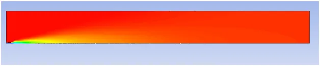
O2 at 5% of water

O2 at 10% of water

O2 at 15% of water

O2 at 20% of water

O2 at 25% of water

O2 at 30% of water

NOx at 5% of water

NOx at 10% of water

NOx at 15% of water

NOx at 20% of water

NOx at 25% of water

NOx at 30% of water

SOOT at 5% of water

SOOT at 10% of water

SOOT at 15% of water

SOOT at 20% of water

SOOT at 25% of water

SOOT at 30% of water

CHARTS:
Co2 at 5% of water
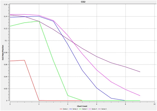
Co2 at 10% of water
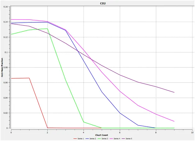
Co2 at 15% of water
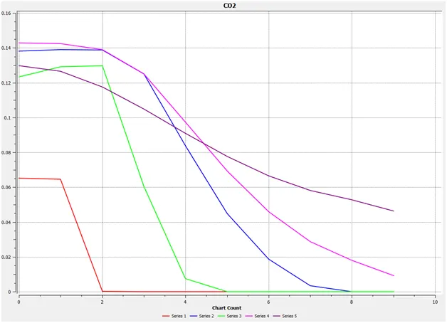
Co2 at 20% of water
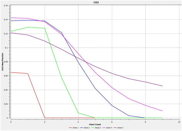
Co2 at 25% of water
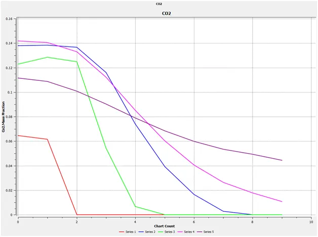
Co2 at 30% of water
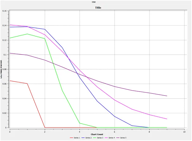
H2o at 5% of water
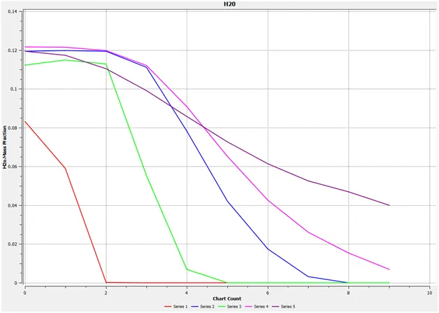
H2o at 10% of water
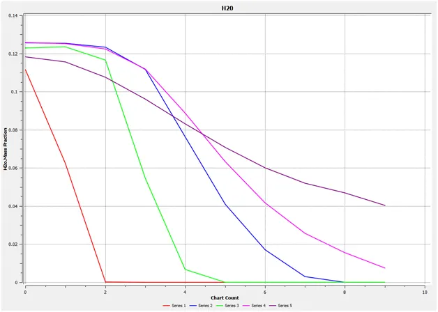
H2o at 15% of water
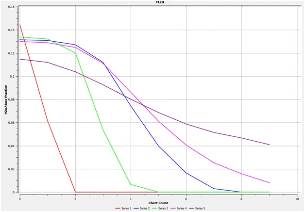
H2o at 20% of water
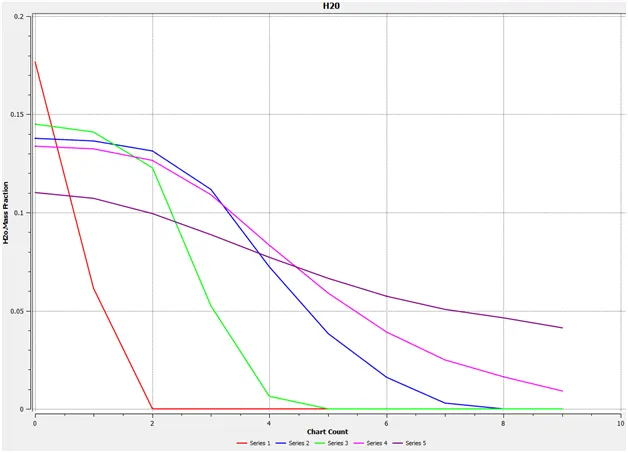
H2o at 25% of water
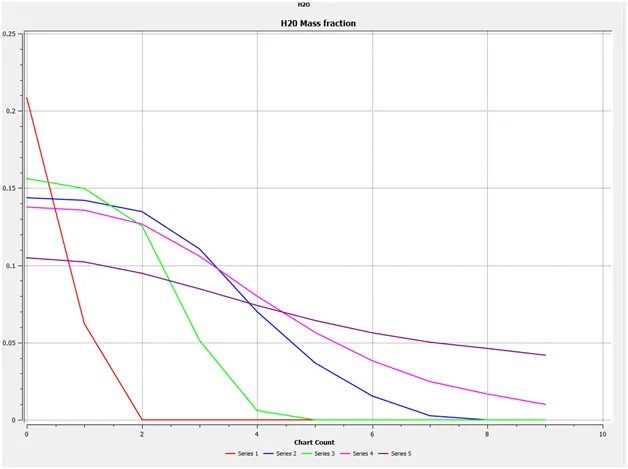
H2o at 30% of water
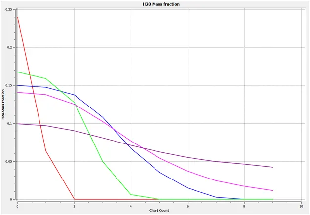
Ch4 at 5% of water
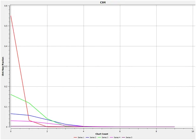
Ch4 at 10% of water
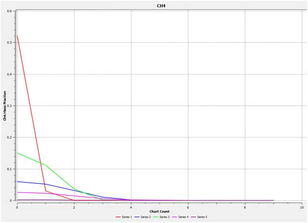
Ch4 at 15% of water
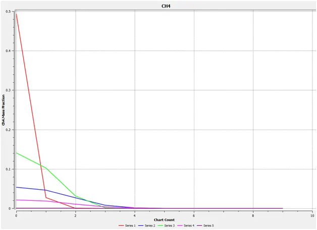
Ch4 at 20% of water
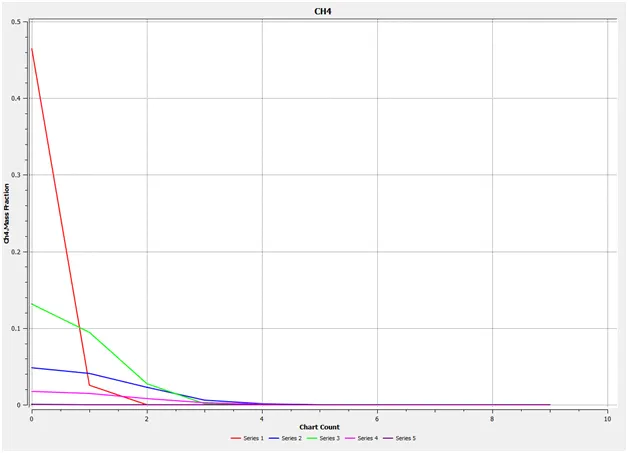
Ch4 at 25% of water
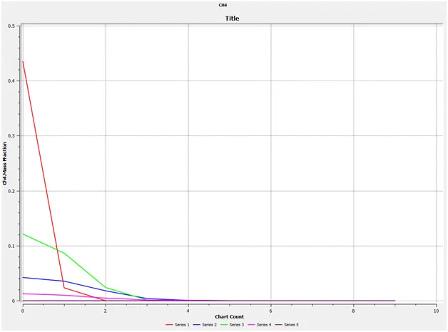
Ch4 at 30% of water
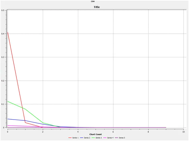
N2 at 5% of water
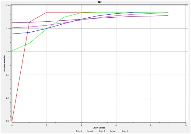
N2 at 10% of water
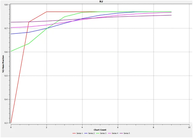
N2 at 15% of water
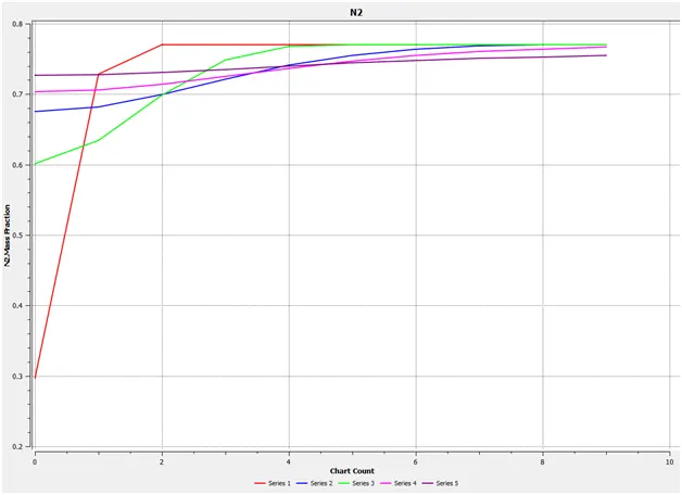
N2 at 20% of water
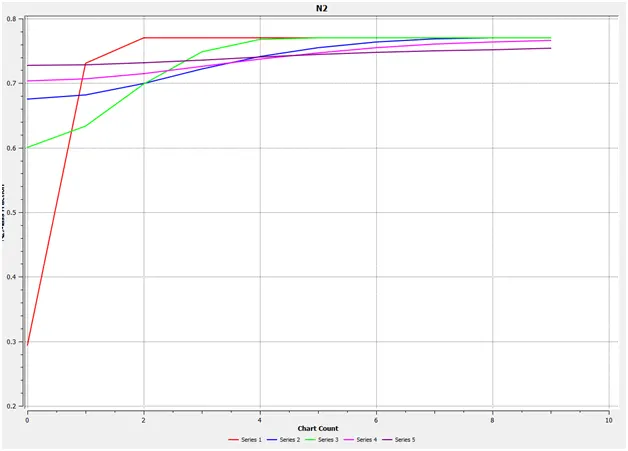
N2 at 25% of water
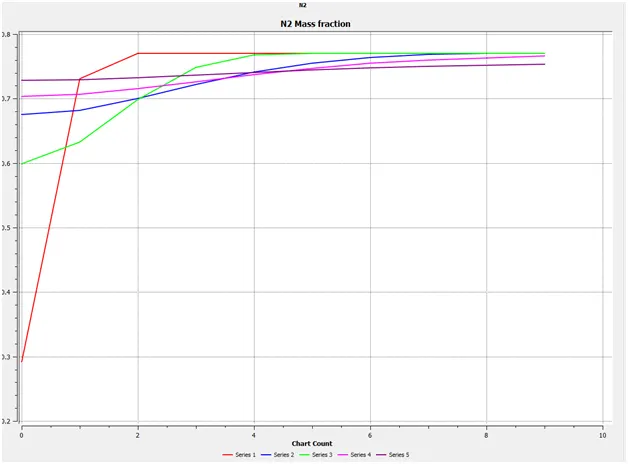
N2 at 30% of water
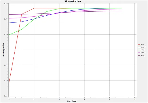
O2 at 5% of water
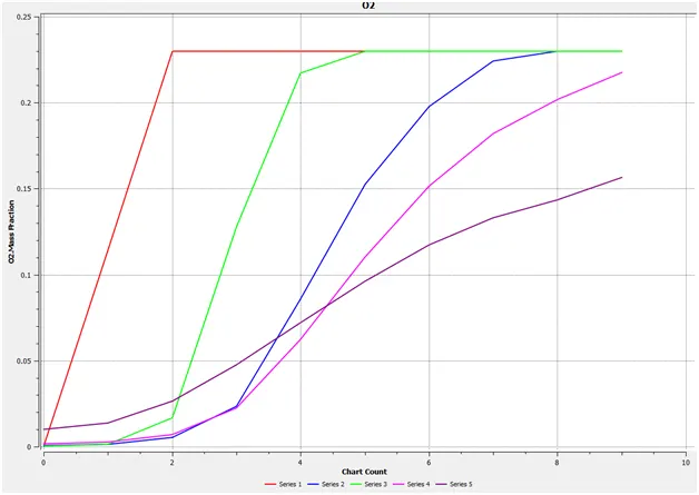
O2 at 10% of water
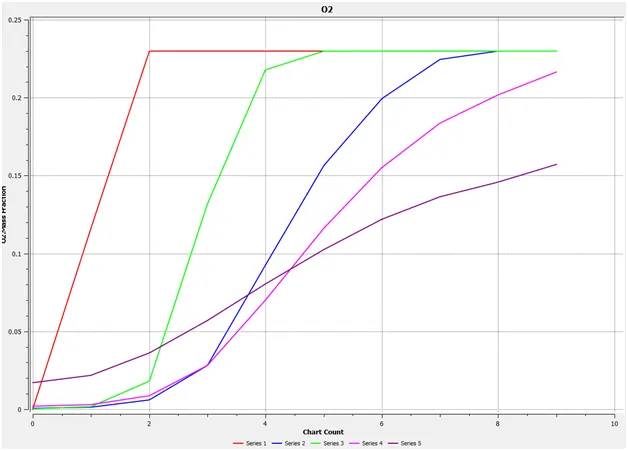
O2 at 15% of water
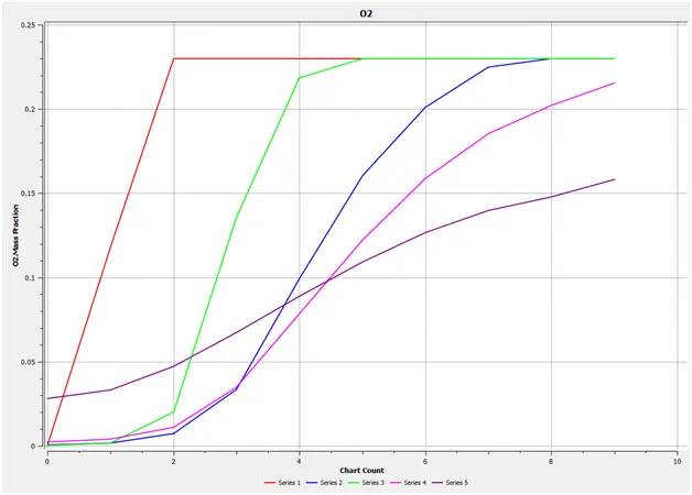
O2 at 20% of water
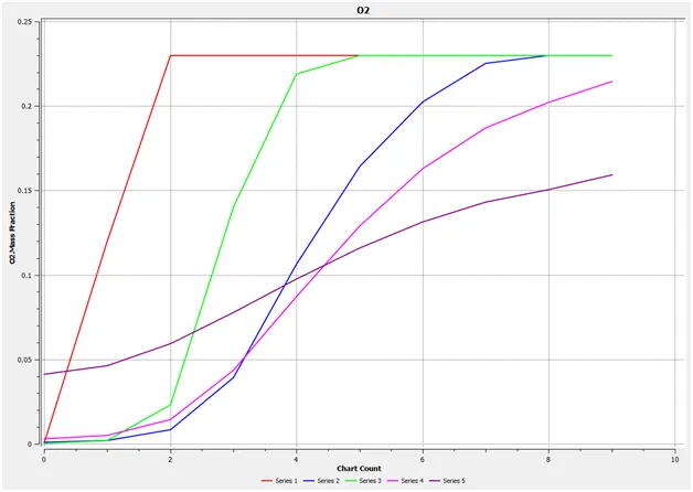
O2 at 25% of water
O2 at 30% of water
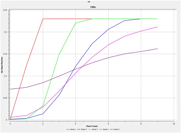
NOx at 5% of water
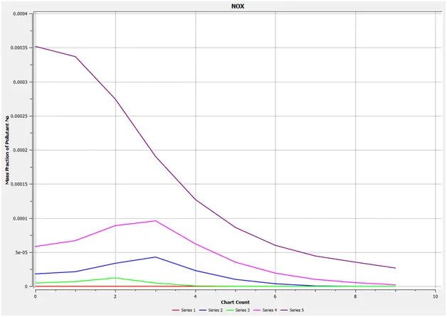
NOx at 10% of water
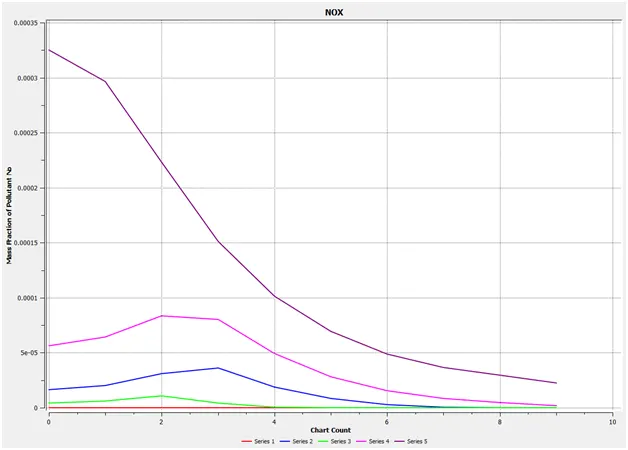
NOx at 15% of water
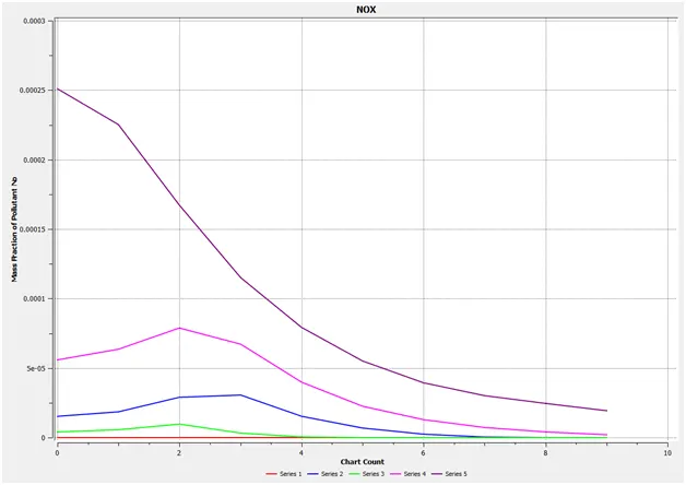
NOx at 20% of water
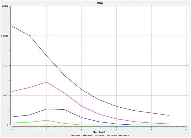
NOx at 25% of water
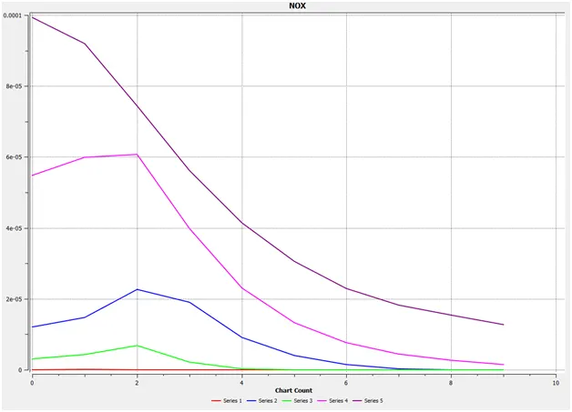
NOx at 30% of water
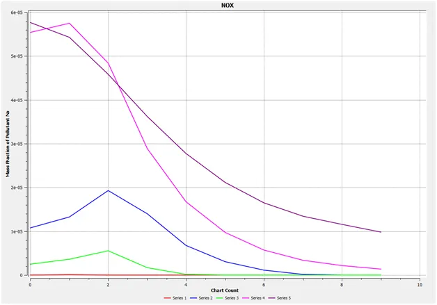
SOOT at 5% of water
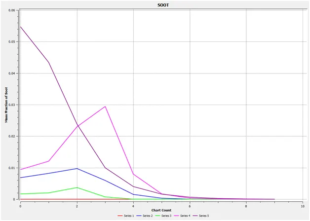
SOOT at 10% of water
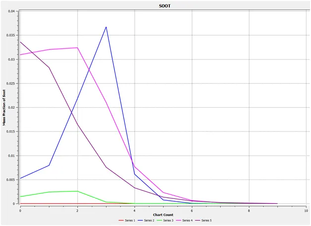
SOOT at 15% of water
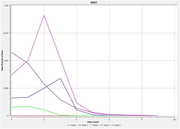
SOOT at 20% of water
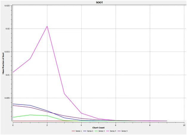
SOOT at 25% of water
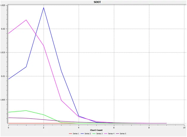
SOOT at 30% of water
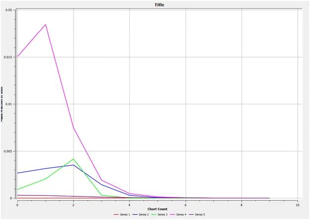
CONCLUSION
- There is a drop in the level of nitrogen oxides as water content in the fuel is increased Similarly, soot levels also decreases
- Temperature also increases as water content is added to the fuel
- Unburn hydrocarbons forms at much faster rate as water is added
- Incomplete combustion could be a result of having water
- The various species of the combustion in the reaction mechanism is seen
- The species transport and the eddy dissipation is applied in this simulation
- Thus it is concluded that the combustion simulation helps to see the detailed chemical kinetics study