Week 9 - Parametric study on Gate valve.
Aim :- Parametric study on Gate valve.
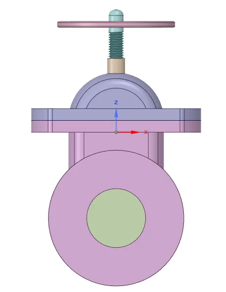
Introduction , theory A gate valve, also known as a sluice valve, is a valve that opens by lifting a barrier (gate) out of the path of the fluid. Gate valves require very little space along the pipe axis and hardly restrict the flow of fluid when the gate is fully opened. The gate faces can be parallel but are most commonly wedge-shaped (in order to be able to apply pressure on the sealing surface).
Gate valves are used to shut off the flow of liquids rather than for flow regulation. When fully open, the typical gate valve has no obstruction in the flow path, resulting in very low flow resistance.[1] The size of the open flow path generally varies in a nonlinear manner as the gate is moved. This means that the flow rate does not change evenly with stem travel. Depending on the construction, a partially open gate can vibrate from the fluid flow.[1]
Gate valves are mostly used with larger pipe diameters (from 2" to the largest pipelines) since they are less complex to construct than other types of valves in large sizes.
At high pressures, friction can become a problem. As the gate is pushed against its guiding rail by the pressure of the medium, it becomes harder to operate the valve. Large gate valves are sometimes fitted with a bypass controlled by a smaller valve to be able to reduce the pressure before operating the gate valve itself.
Gate valves without an extra sealing ring on the gate or the seat are used in applications where minor leaking of the valve is not an issue, such as heating circuits or sewer pipes.
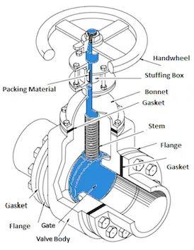
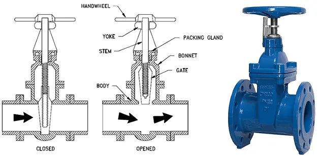
Socket or butt-welding end-gate valves in air, fuel gas, feedwater, steam, lube oil, and other systems are typical applications. Threaded-end gate valves may be used in air, gaseous, or liquid systems. Concern for leakage from threaded connection can be addressed by seal welding the threaded connection or by using thread sealants, as appropriate. In low-pressure and low-temperature systems such as fire protection systems’ water piping or water distribution pipelines, flanged gate valves are commonly used
Solving & Modelling approach
Typical Gate Valve Applications
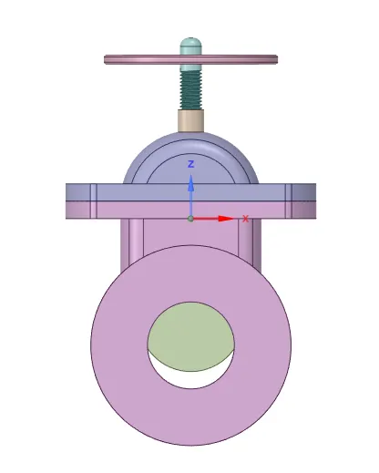
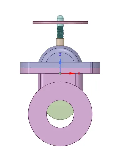
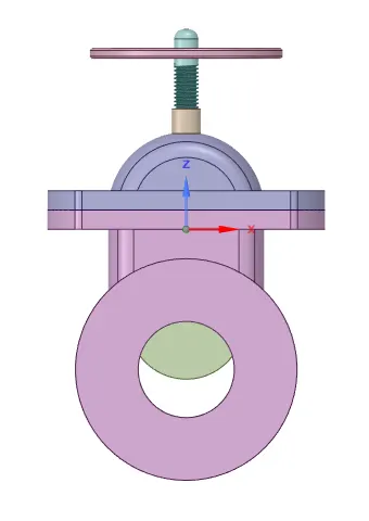
Geometry section
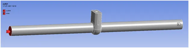
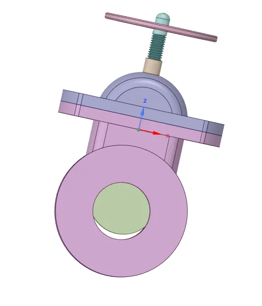
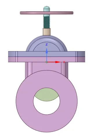
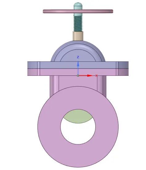
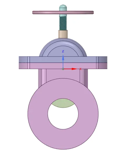
Here we import the geometry file
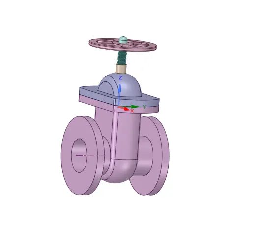
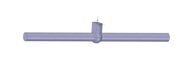
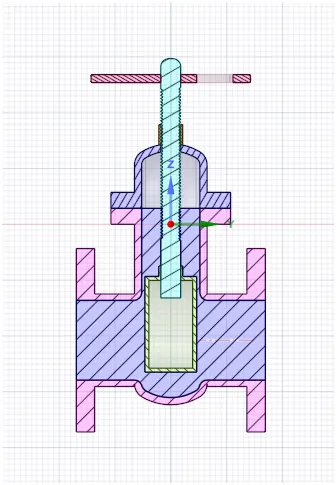
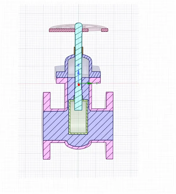
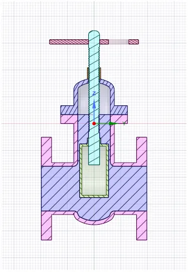
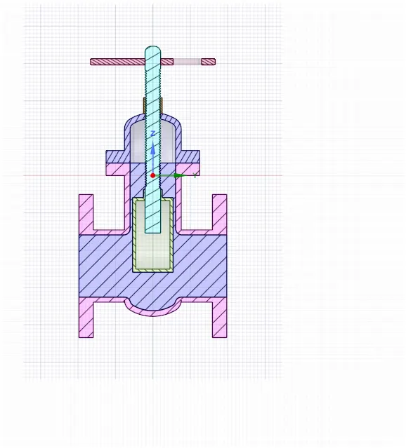
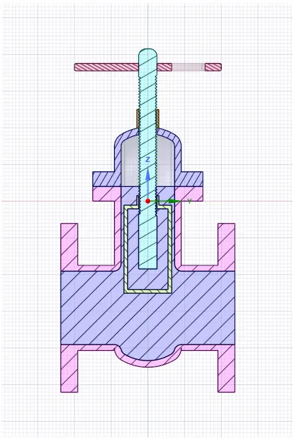
Then extract the fluid volume in the geometry part by using selecting edges methods
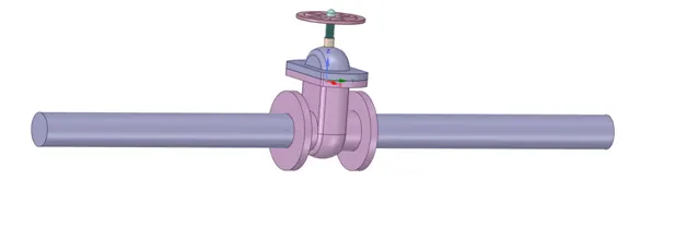
And its actual volume look like given figure below
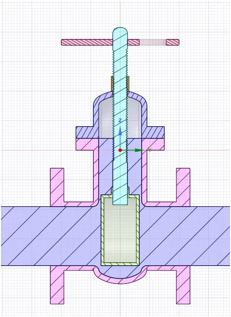
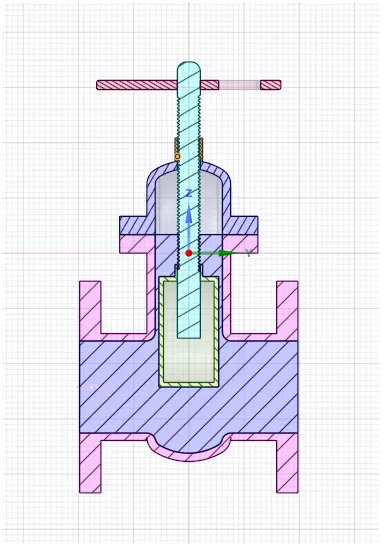
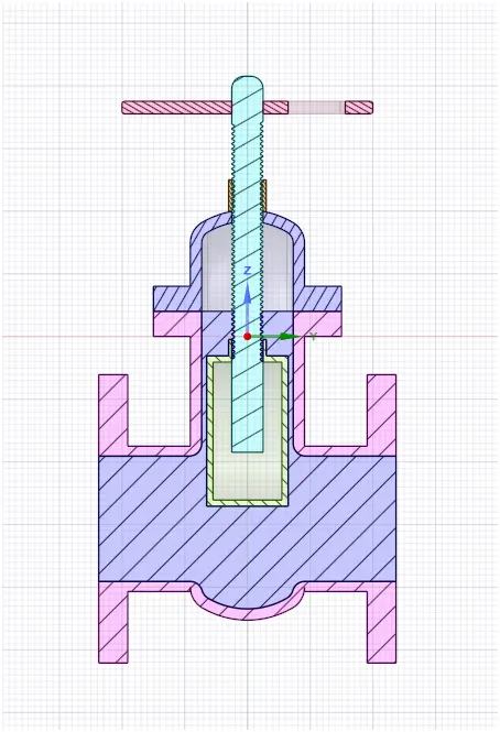
Then open the gate of valve for 10 mm and set parameter of gate valve in group 1.
In this figure shown the gate valve is opening for 10 mm
Meshing section
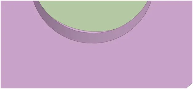
First set the element size for meshing and input other parameter.
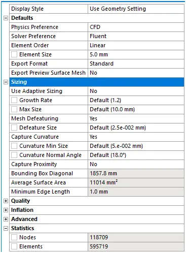
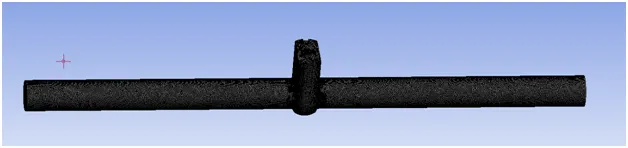
After putting input of mesh then update the mesh or generate the mesh.
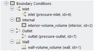
After meshing name the side of geometry as inlet and outlet
Setup section

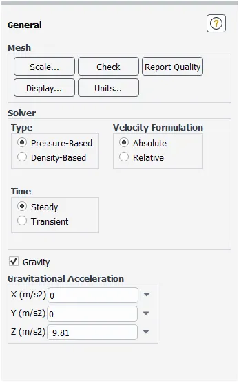
Put general setting of setup as we seen below figure
Here we use gravitation force in z direction
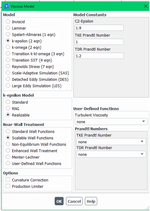
Here we use k epsilon model of viscous model
With stable wall function
Here we have taken Pressure for inlet = 10 Pa.
Typically for Pipe flow, pressure of 10 Pa is acceptable.
In Viscous model, we have taken K-Epsilon model.
The Reason behind choosing the K-Epsilon Viscous model is characteristic of the flow, which is turbulent.
For Reynolds No. about 2000 and more, flow is turbulent. So we have taken K Epsilon Viscous model.
But here, we have given Pressure Inlet, instead of Velocity Inlet. So knowing the velocity of the flow for correct Reynolds No. is required.
So, to know the velocity of the flow, we have to go for initializing the solution. So, go to Solution, and select Standard Initialization, and Initialize from Inlet.
After initialization, we can get the correct velocity and calculate the Reynolds No. and from that, we can decide for the appropriate viscous model.
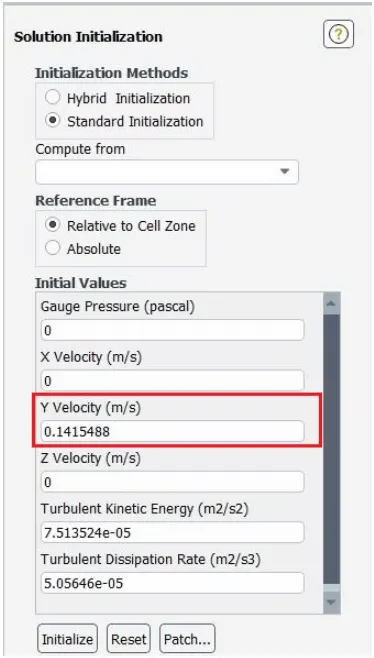
In above image, we can see that Velocity at the inlet will be 0.1415488 m/s in Y-Direction
So, for Reynolds No.,
p=998.2 Kg/m³
V=0.1415488 m/s
D = 0.1 m
Re=[pVD]/μ
= [998.2 0.1415488 0.1]/0.001003
= 14087.14
Here, Reynolds No. is 14087.14, which is more than 2000.
So the flow is turbulent.
So the viscous model will be K-Epsilon.
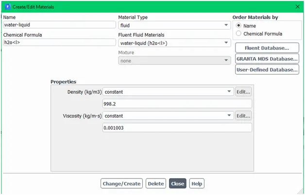
Then after choose material here we choose water as material fluid which flow inside the pipe
Then set up boundary condition here we set inlet condition is pressure inlet at 10 psi
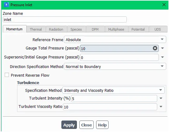
Here we are interested to know mass flow rate at outlet section
So we create mass flow rate graph
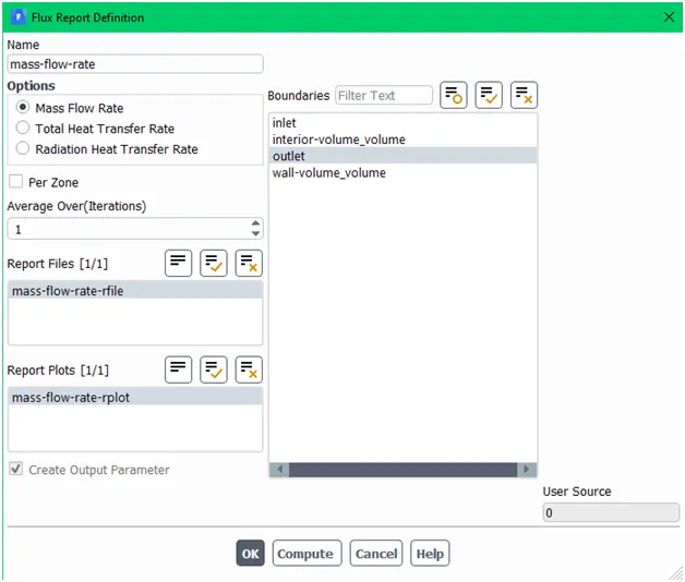
After setup all condition in setup part then calculate or run for 500 iteration.
Result section
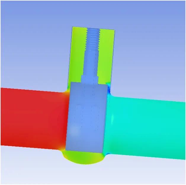
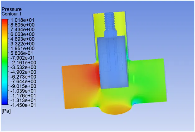
In the above figure show pressure contour of gate valve as we show in left side of gate valve is in red color which indicate high pressure and in right side of gate valve is in light blue color which indicate low pressure at outlet of pipe. This pressure contour is at 10 mm opening of gate valve .
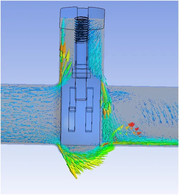
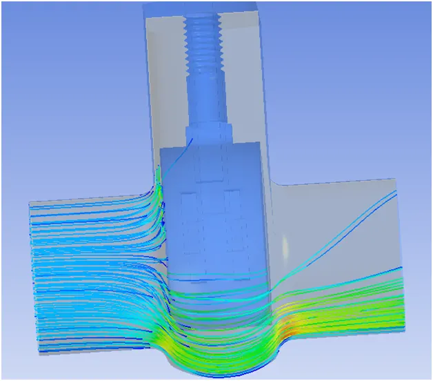
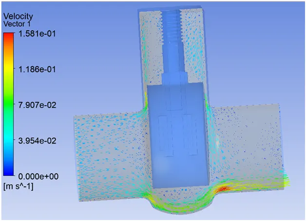
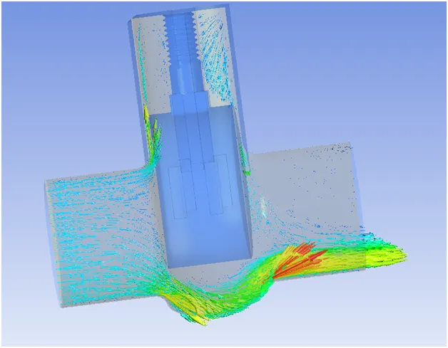
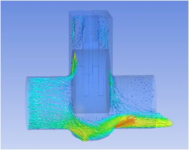
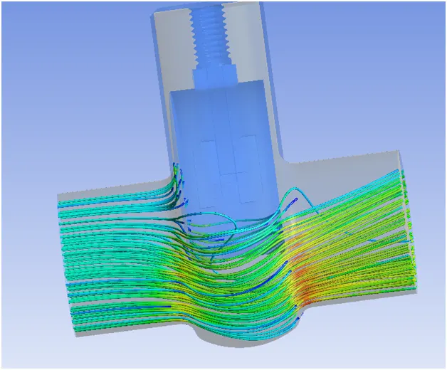
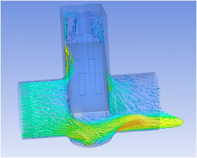
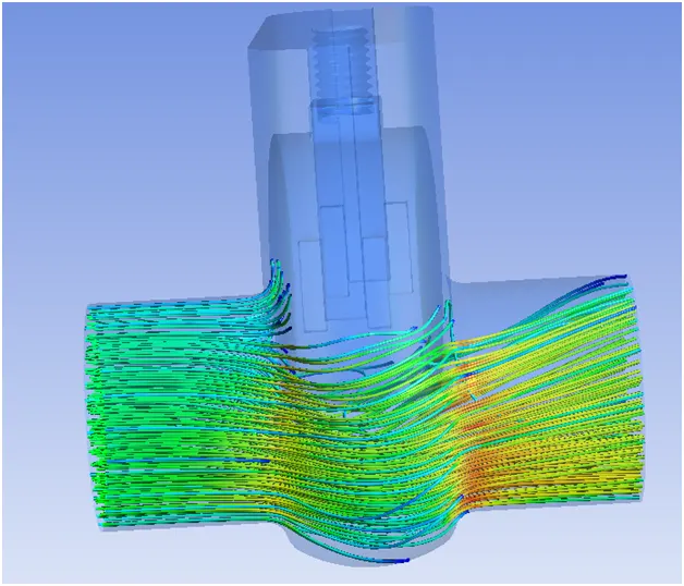
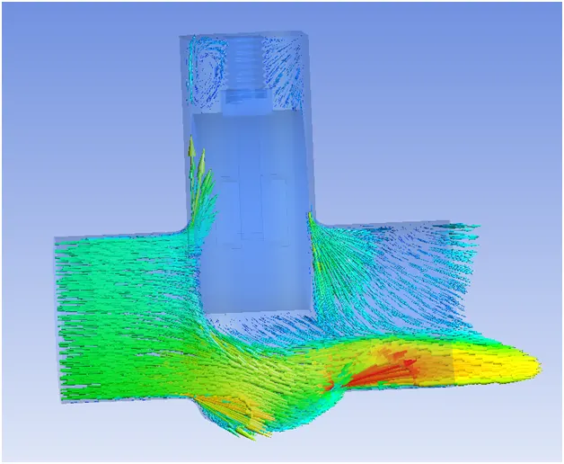
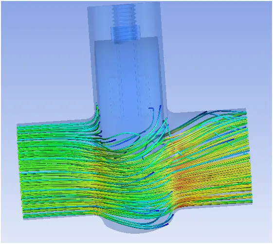
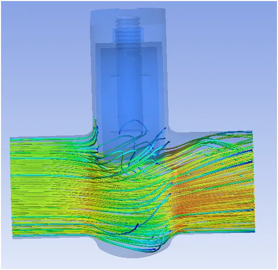
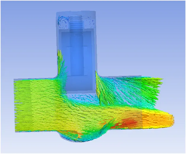
Above figure is show how the fluid is pass through the 10mm opening the gate valve and as we show in figure how the water fluid is pass through the gate valve and in above section of gate there are some leakage of water.
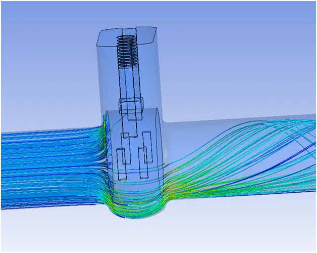
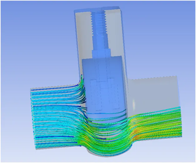
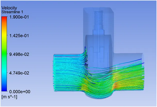
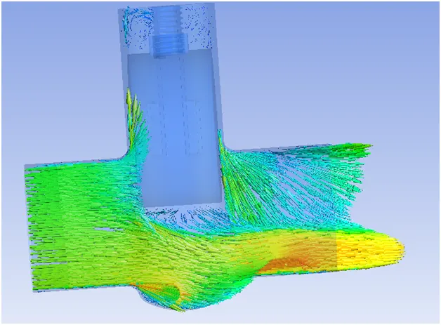
In this stream line figure show how the velocity is change during and after the passing the gate valve here blue color is indicate the water is stagnant and at opening the gate valve the velocity of water is highest and after passing the gate valve the velocity is decrease as we shon the change in color.
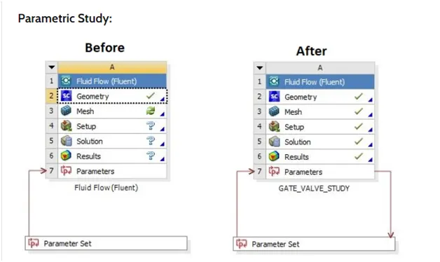
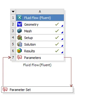
Here we can see the parametric option this option is used to study different design point in the same simulation. Here we have to put the input value.
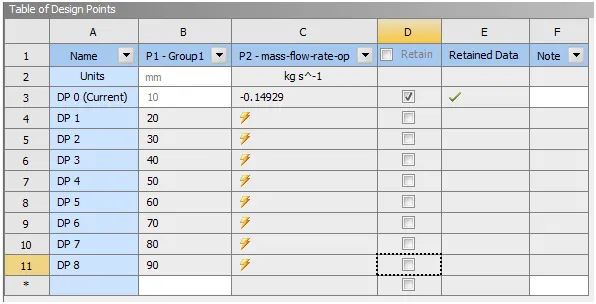
As we show in above figure DP 1 row is fill and also tick all row but from 3 to 11 rows are not filled but here we put all input in group 1 column. Here the value of group 1 is the opening of gate valve in mm which is from 10mm to 90 mm.
After set all condition in parametric setup then we have to calculate.
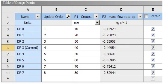
After calculating all value of group 1 then we have all mass flow rate of gate opening which is shown in above figure. From this value we can easily calculate the flow coefficient and flow factor.
Flow coefficient
The flow coefficient of a device is a relative measure of its efficiency at allowing fluid flow. It describes the relationship between the pressure drop across an orifice valve or other assembly and the corresponding flow rate. Mathematically the flow coefficient Cv (or flow-capacity rating of valve) can be expressed as :
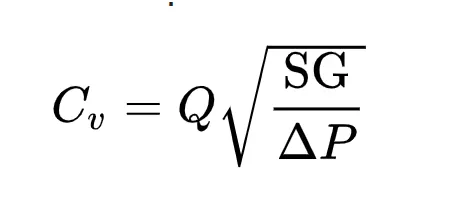
where:
Q is the rate of flow (expressed in US gallons per minute),
SG is the specific gravity of the fluid (for water = 1),
ΔP is the pressure drop across the valve (expressed in psi).
In more practical terms, the flow coefficient Cv is the volume (in US gallons) of water at 60 °F that will flow per minute through a valve with a pressure drop of 1 psi across the valve. The use of the flow coefficient offers a standard method of comparing valve capacities and sizing valves for specific applications that is widely accepted by industry. The general definition of the flow coefficient can be expanded into equations modeling the flow of liquids, gases and steam using the discharge coefficient.
Flow factor
The metric equivalent flow factor (Kv; commonly used everywhere else in the world with the exception of the United States) is calculated using metric units :
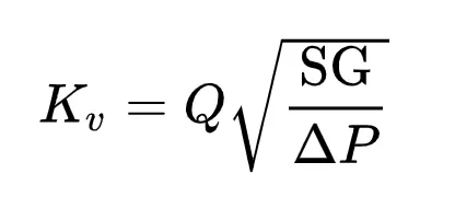
where[3][4]
Kv is the flow factor (expressed in ).
Q is the flowrate (expressed in cubic metres per hour [ ]),
SG is the specific gravity of the fluid (for water = 1),
∆P is the differential pressure across the device (expressed in [bar]).
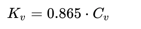
Kv can be calculated from Cv using the equation:
|
CASE |
OPENING OF GATE VALVE IN mm |
MASS FLOW RATE |
|
1 |
10 |
-0.14929 |
|
2 |
20 |
-0.23023 |
|
3 |
30 |
-0.33908 |
|
4 |
40 |
-0.44954 |
|
5 |
50 |
-0.56601 |
|
6 |
60 |
-0.65995 |
|
7 |
70 |
-0.75412 |
|
8 |
80 |
-0.82944 |
|
|
|
|
Calculation
Flow coefficient
SG = 1000/998.2
= 1.00180 Which is almost equal to 1 so
The value if SG = 1
ΔP = pressure difference of outlet and inlet but outlet pressure is 0.000145037
Which is neglected so our pressure difference is 10psi.
SG = Q*√1/10
Flow factor
Kv = 0.865*Cv
Case 1
SG = 0.14929*√1/10
= 0.04727
Kv = 0.865*0.04723
= 0.04089
Case 2
SG = 0.23023*√1/10
= 0.07280
Kv = 0.865*0.07280
= 0.06297
Case 3
SG = 0.33908*√1/10
= 0.10722
Kv = 0.865*0.10722
= 0.09275
Case 4
SG = 0.44954*√1/10
= 0.14215
Kv = 0.865*0.14215
= 0.12296
Case 5
SG = 0.56601*√1/10
= 0.17898
Kv = 0.865*0.17898
= 0.15482
Case 6
SG = 0.65995 *√1/10
= 0.20869
Kv = 0.865*0.20869
= 0.04355
Case 7
SG = 0.75412 *√1/10
= 0.23847
Kv = 0.865*0.23847
= 0.20627
Case 8
SG = 0.82944 *√1/10
= 0.26229
Kv = 0.865*0.26229
= 0.22688
|
CASE |
OPENING OF GATE VALVE IN mm |
MASS FLOW RATE |
FLOW COEFFICIENTS |
FLOW FACTOR |
|
1 |
10 |
-0.14929 |
0.04727 |
0.04089 |
|
2 |
20 |
-0.23023 |
0.07280 |
0.06297 |
|
3 |
30 |
-0.33908 |
0.10722 |
0.09275 |
|
4 |
40 |
-0.44954 |
0.14215 |
0.12296 |
|
5 |
50 |
-0.56601 |
0.17898 |
0.15482 |
|
6 |
60 |
-0.65995 |
0.20869 |
0.04355 |
|
7 |
70 |
-0.75412 |
0.23847 |
0.20627 |
|
8 |
80 |
-0.82944 |
0.26229 |
0.22688 |
Pressure contour
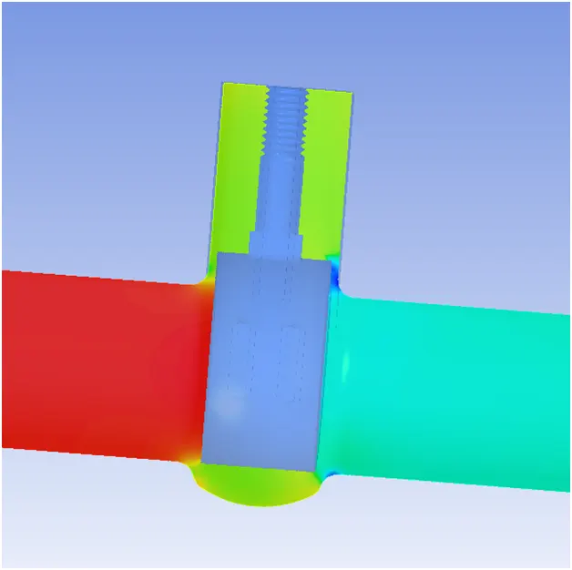
10 mm
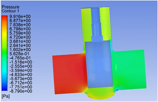
20mm
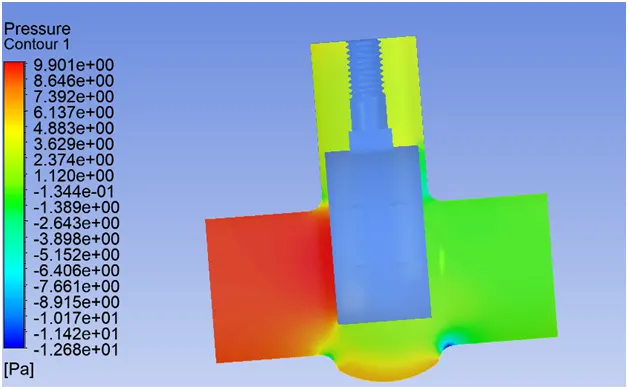
30 mm
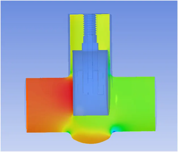
40 mm
50 mm
60 mm
70 mm
80 mm
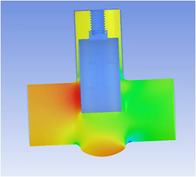
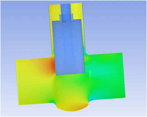
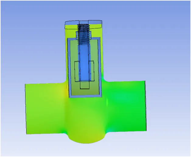
All contour in pressure decreasing order.
All pressure of valve are shown in above figure where in figure 1 we show the more pressure difference but when we come from figure nu 1 to figure 8 then the pressure difference is decrees and finally when valve is open for 80 mm then no pressure difference is occur which show that fluid has enough space to pass the gate valve.
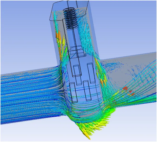
10 mm
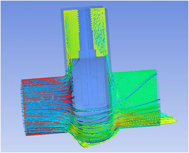
20 mm
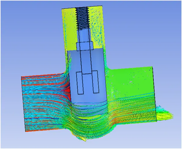
30 mm
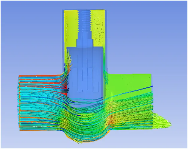
40 mm
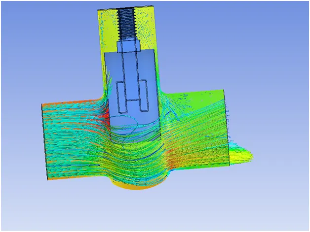
50 mm
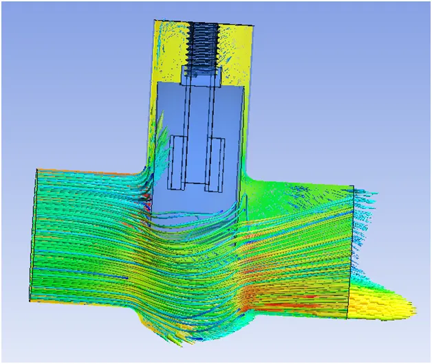
60 mm
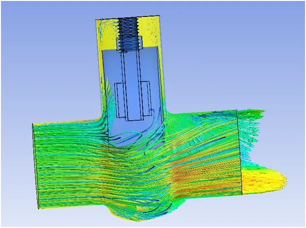
70 mm
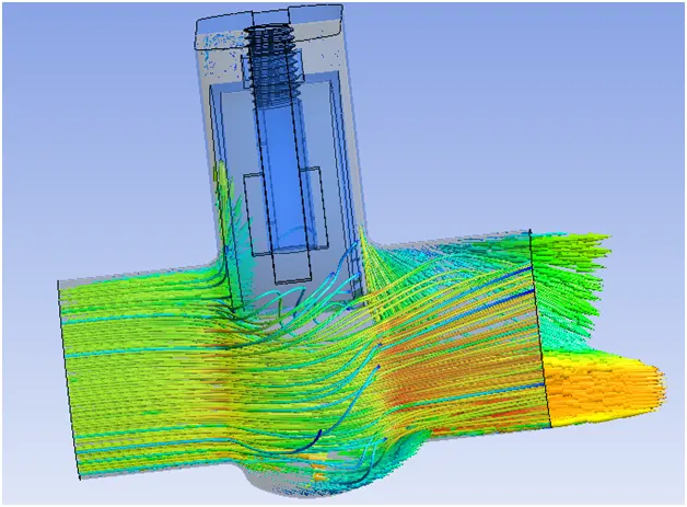
80 mm
Conclusion:
- We can conclude from observations that velocity in the first case is very low. As opening or lift of the Gate Disc increases, velocity of the flow increases. We can observe that at the front or inlet side of the valve, pressure is high. As flow passes through the valve opening, it decreases. And at the outlet there are no any restrictions to the flow, so pressure becomes 0.
- It means there is minimum Pressure Drop.
- There is a gradual increase in Mass Rate, Flow Coefficient and Flow Factor as Lift of the Gate Disc increases, or from 10% to 80%, or 10 mm 80 mm.When the valve if fully open, Mass Flow rate and Flow Coefficient and Flow Factor becomes maximum.
- Thus, parametric study helps to analyze the different positions of valve opening and gives the benefit to get easily and quick results.