Week 3 - External flow simulation over an Ahmed body.
AIM= Analysis flow and Turbulence Structures in the Wake of a Simplified Car Model (Ahmed Model)
The aim of the present study is to investigate experimentally the aerodynamic behaviour of the Ahmed body under various geometrical conditions and to test the ability of the CFD simulation
OBJECTIVE = analysis the variable of flow parameters.
SOFTWARE USED = o ANSYS, SpaceClaim - To prepare FV model and setup cases of Ahmed Body Geometry.
o ANSYS, Meshing - To mesh the given model.
o ANSYS, FLUNET - To setup the boundary conditions and to solve the given model.
o ANSYS, CFD Post - To perform Post Processing.
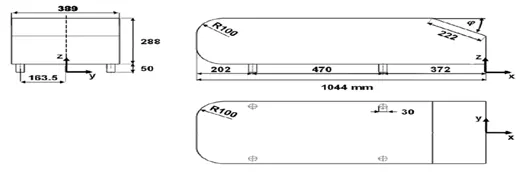
INTRODUCTION = The Ahmed Body was first created by S.R. Ahmed in his research “Some Salient Features of the Time-Averaged Ground Vehicle Wake” in 1984. Since then, it has become a benchmark for aerodynamic simulation tools. The simple geometrical shape has a length of 1.044 meters, height of 0.288 meters, and a width of 0.389 meters. It also has 0.5-meter cylindrical legs attached to the bottom of the body and the rear surface has a slant that falls off at 40 degrees.
Solving & Modelling approach
Geometry
The geometrical measurement of Ahmed body is given as shown in figure below
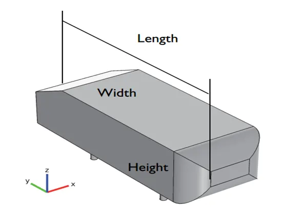
In 3D view
By using this dimensions we have to design Ahmed body model in ANSYS SPACECLAIM
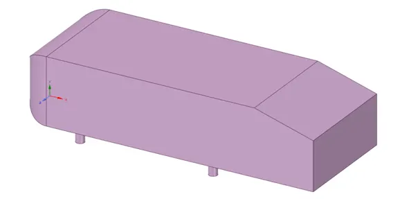
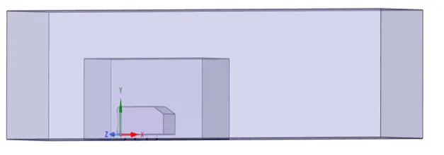
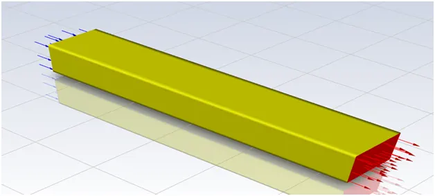
Our aim of this model is analyse external flow over an Ahmed body so we have to create wind tunnel and in ANSYS we can move with enclosure option.
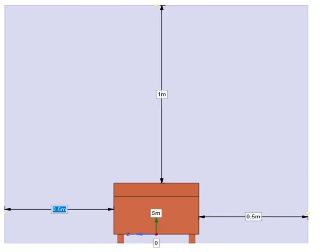
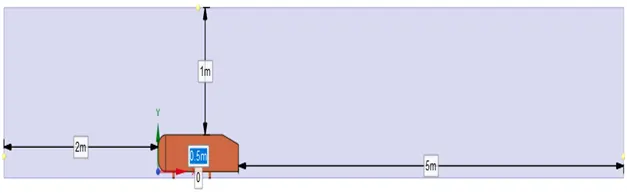
After creating enclosure it look like the Ahmed body is placed in a tunnel.Here we have to analyse the surface of the body and when we use this single enclosure to analyse the flow reaction over the body then it take a lot of time to simulate the simulation due to more number of meshing element and number of nodes so to fix this problem we can create one more small enclosure around the Ahmed body but this smaller enclosure is small in size as compare to bigger enclosure .
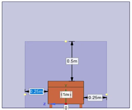
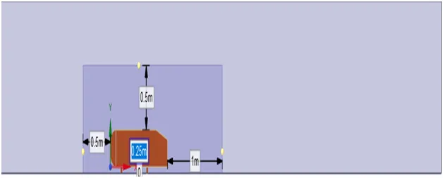
After create enclosure it look like as shown in figure below.
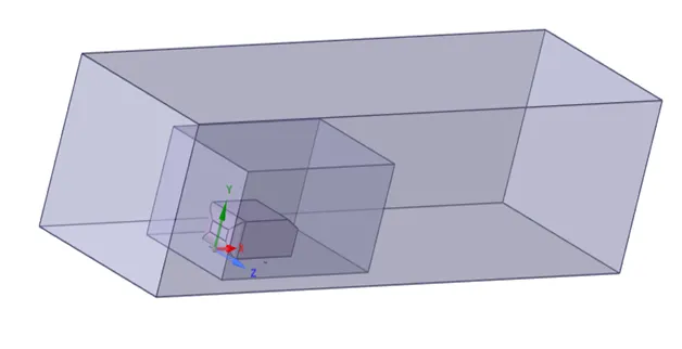
After enclosure we have to create plane at the middle section of the Ahmed body in direction of X,Y coordinate which is perpendicular to Z axis.For this we have to choose the plane option in SpaceClaim and then click on the meeting on the X,Y,Z coordinates axes. Then it automatic create three plane but here only one plane is use full for us which is normal to Z direction and other two plane is deleted.
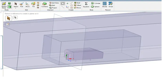
After deleting other two plane it look like given in figure.
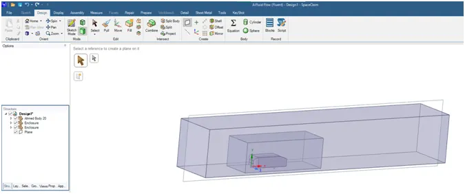
Now we have to make section plane in X,Y direction by selecting section plane option
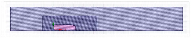
As we seen in section plane in above figure in the area of small enclosure the hatches line of cutting section plane is over lapping one another.
Due this overlapping the mesh which we will generate in mess section is also getting over lapped in small enclosure and we will not get accurate result of simulation so first we have to remove this over lapping hatches line of section plane. By using interference option we can fix this overlapping problem.
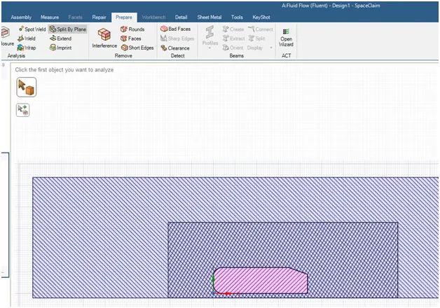
It automatic detect the overlapping section and is resolve it
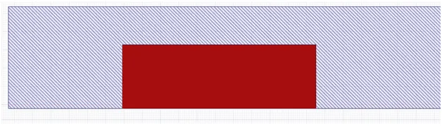
And finally we get a clear section view.
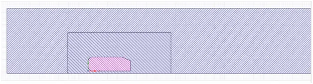
Now we finished our geometry section .
Meshing
In meshing part we divide the whole geometry in three parts
Outer enclosure
Inner enclosure
Ahmed body
For produce good result meshing part play very important role in simulation so produce good mesh we multiple tools of mesh
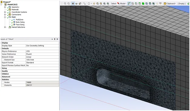
So for outer enclosure we use multi Zone mesh because multi zone mesh is easily connect its boundary with another mesh boundary which is shown in given figure. Here mesh and element size is 100.
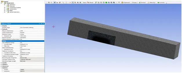
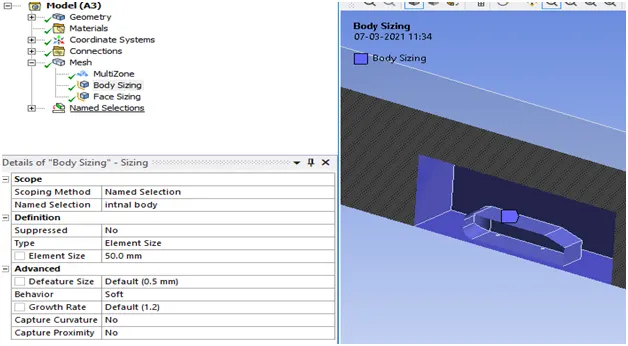
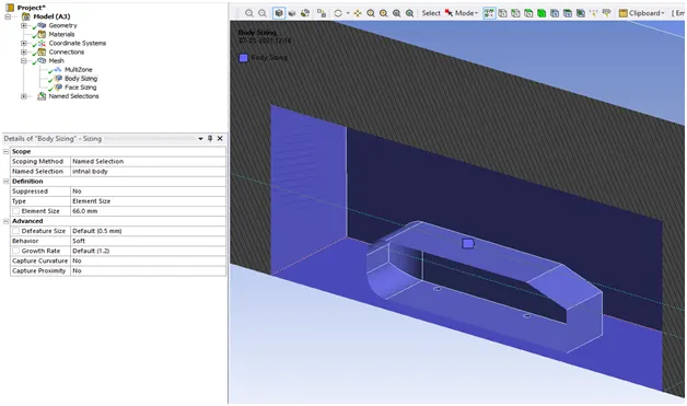
At inner enclosure we use different mesh tool called body sizing which is given below.
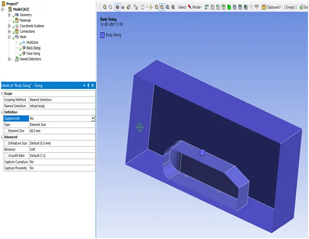
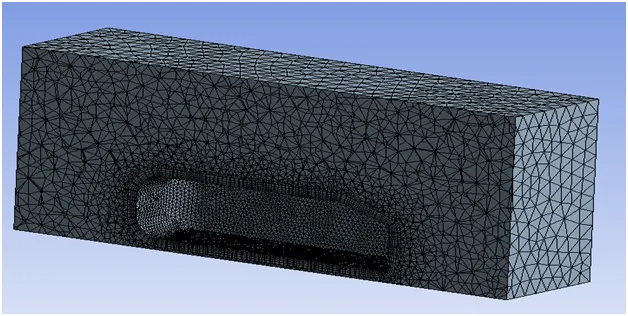
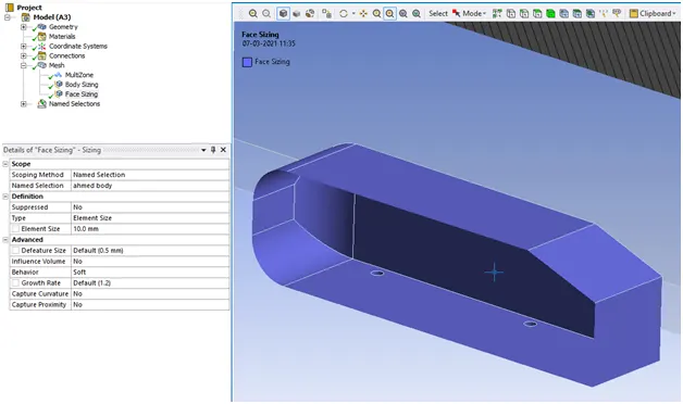
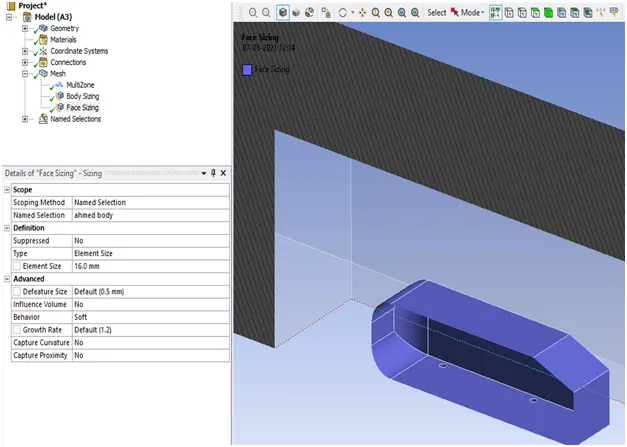
And for meshing the surface of Ahmed body we use face sizing
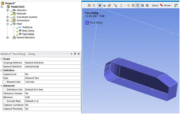
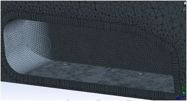
At the surface of Ahmed body we use inflation layer which provide good result in simulation
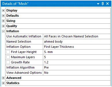
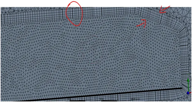
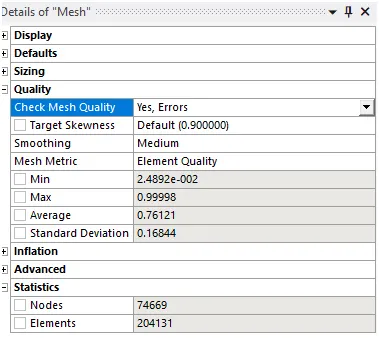
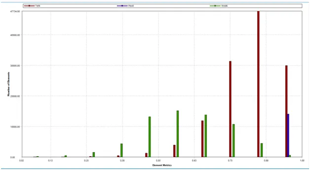
Over all mesh quality
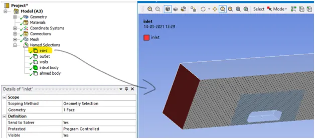
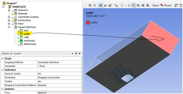
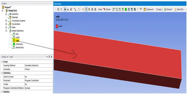
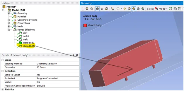
Naming the geometry
Inlet
Outlet
Wall
Internal body

Ahmed body
Setup
In setup part we apply condition and check the simulation result here we have to apply try and failed method for good result of simulation.
Here we use pressure based solver and steady case simulations.
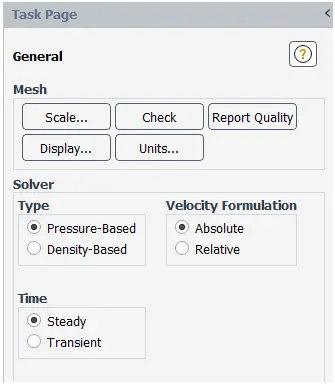
In this simulation we use 25m/s velocity and it is less than 0.3 mach that’s why we use pressure based solver for simulation.
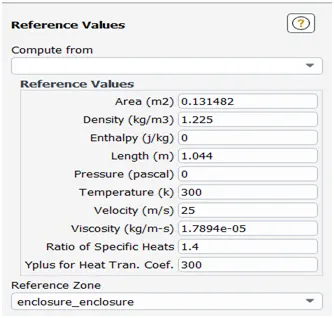
Reference values
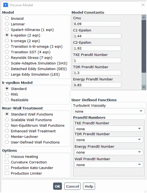
In viscous model k-epsilon model is used because we want result near the surface of Ahmed body.
Inlet condition
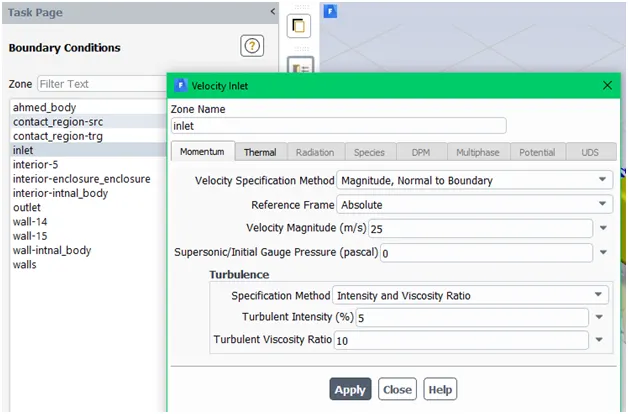
Velocity magnitude is 25m/s
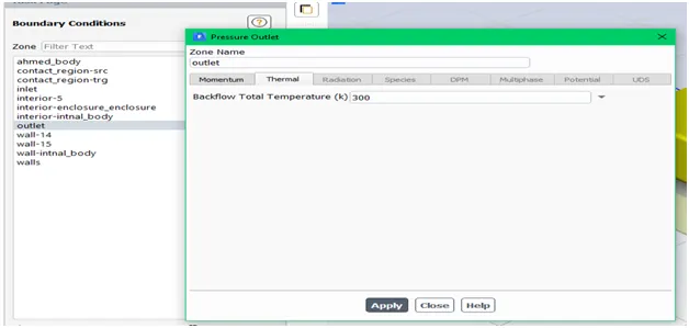
Temperature of fluid is 300k.
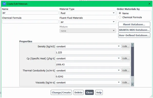
And fluid flow is air.
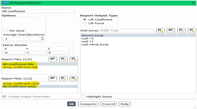
And for calculate drag and lift coefficients
After define condition create a plane and then create contours of velocity and pressure on that plane
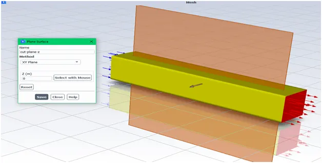
Creating plane and name that plane is cut plane z and it’s normal to z direction
And hit the calculate option for 300 iterations
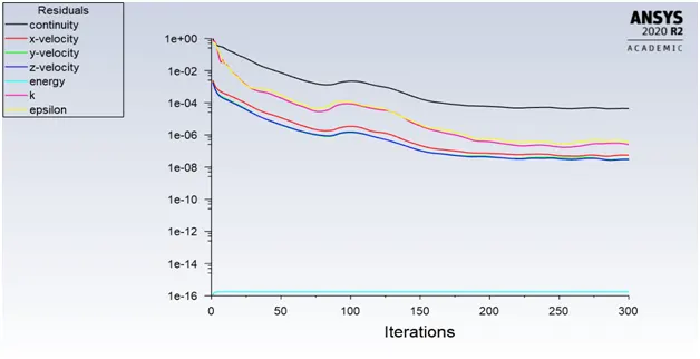
After completing the iterations we got result.
Residual
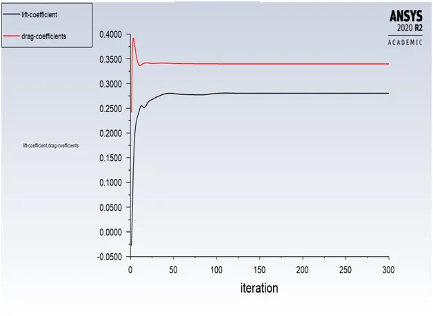
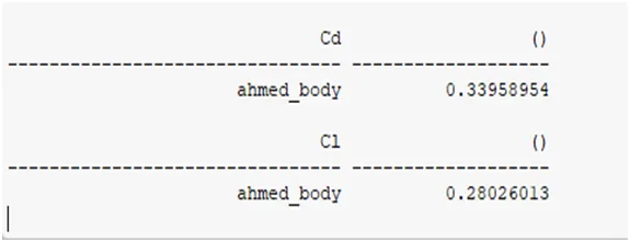
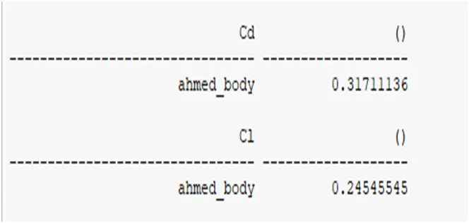
Drag and lift coefficients
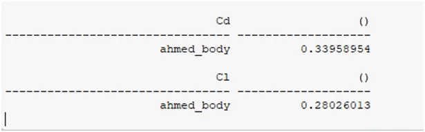
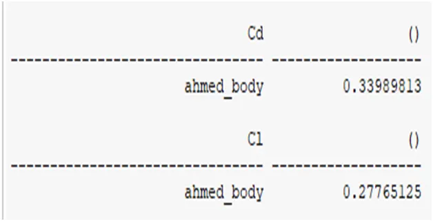
Drag and lift force coefficient value is
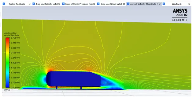
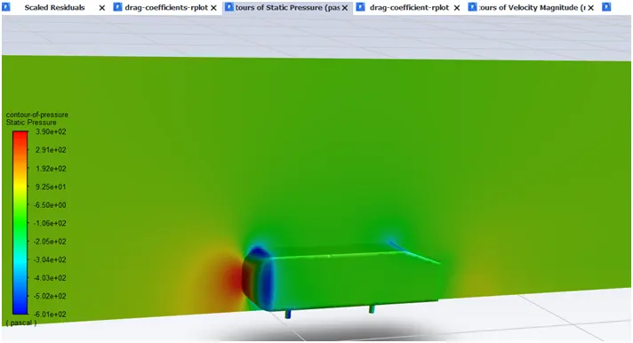
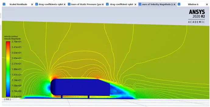
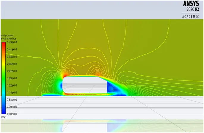
Velocity and pressure contours are given below
Velocity Contour
Pressure contour
ANSYS, CFD Post
CFD post section provide us more tools to check the more accuracy of simulations and here some tool are very important by using that we can check the flow parameters in precise manner or in detail.
First we have to create a plane in the normal direction of Z
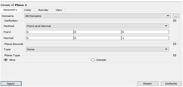
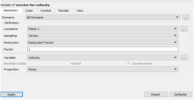
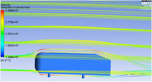
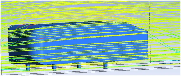
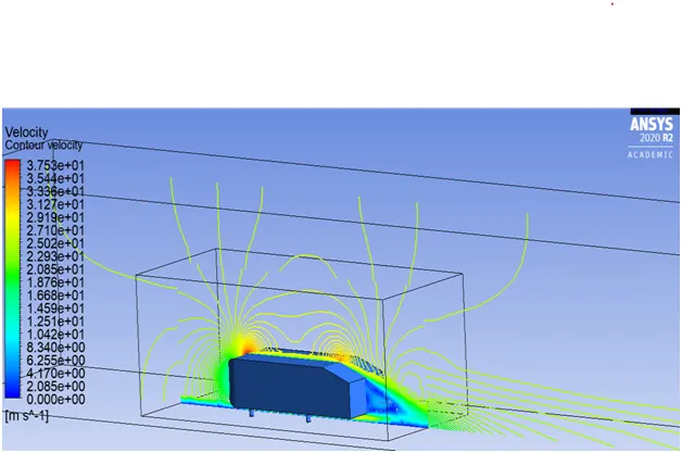
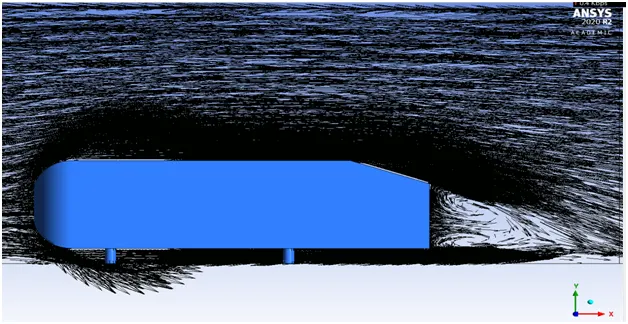
After creating XY plane we can able to observe vector for velocity and streamline on Ahmed body
- Vector for velocity

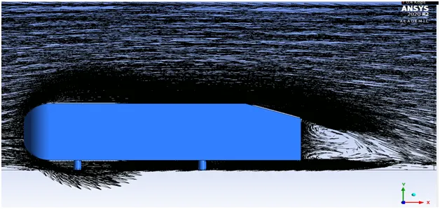
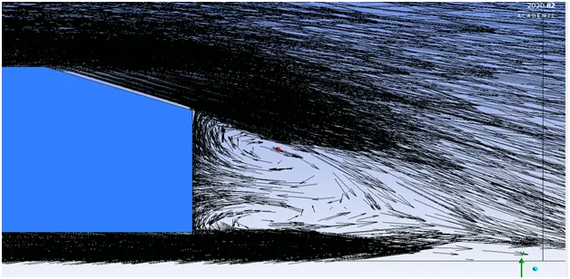
Wake region of Ahmed body
- Streamline on Ahmed body
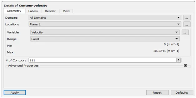
Contour velocity
Expected Results:
Velocity and pressure contours
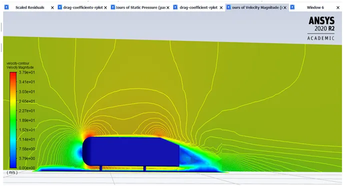
Velocity contour
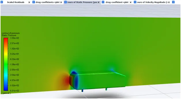
Pressure contour
The drag coefficient plot for a refined case.
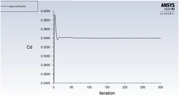
Drag coefficient for velocity 25m/s
Magnitude of lift and drag coefficients are.
The vector plot clearly showing the wake region.
Perform the grid independency test and provide the values of drag and lift with each case.
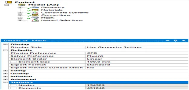
In grid dependency test here we perform three different case and in each case it have different number of elements and nodes
Case1
Number of element 451240
Number of nodes 154529
Case 2
Number of element 204131
Number of nodes 74669
Case 3
Number of element 185238
Number of nodes 68804
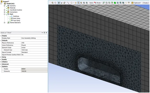
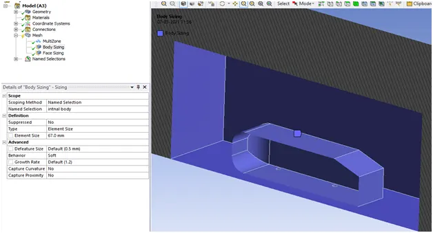
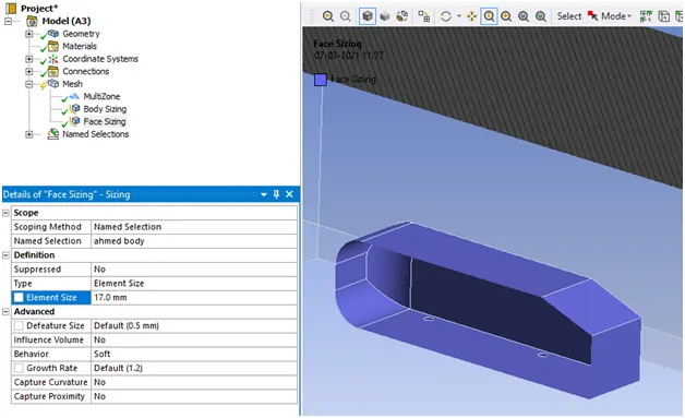
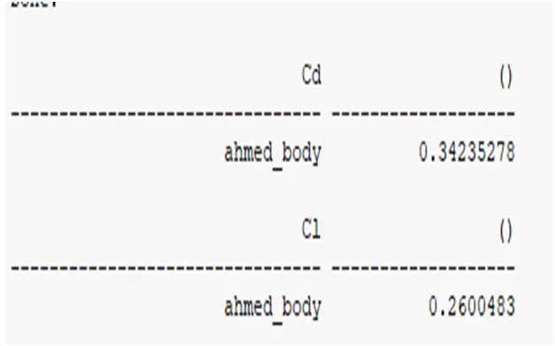
Table of grid dependency test result.
|
Number of elements |
Number of nodes |
Body sizing |
Face sizing |
Value of CD (DRAG COEFFICIENTS) |
Value of CL (LIFT COEFFICIENTS) |
|
|
CASE 1 |
451240 |
154529 |
50.0MM |
10.0MM |
0.31711136 |
0.24545545 |
|
CASE 2 |
204131 |
74669 |
66.0MM |
16.0MM |
0.33989813 |
0.27765125 |
|
CASE 3 |
185238 |
68804 |
67.0MM |
17.0MM |
0.34235278 |
0.2600483 |
Q1. Describe Ahmed's body and its importance.
- The Ahmed body is simplified car body used in automotive field to study the impact of the flow pattern on the drag. The external aerodynamics of the car defines many major traits of an automobile like stability, comfort and fuel consumption at high speeds. The flow around the vehicle is characterized by high turbulent and three dimensional flow separations as well as there is a growing need for more insight into the physical features of these dynamical flows. The Ahmed Body is a simplified car, used in automotive field to investigate the flow analysis and find the wake flow around the body. Ahmed body is made up of round front part, a moveable z slant plane in the rear of the body to study the detachment phenomena at different angles, and a rectangular box which link the front part and the rear slant plane. The principal objective to study such a simplified car body is to tackle the flow processes involved in drag production. Through perceiving the mechanisms involved in creating drag one can be able to design a car to minimize drag and therefore reducing fuel consumption and maximize vehicle performance.
Importance
Ahmed body represents the simplified ground vehicle geometry of a bluff body type. Its shape is simple enough for accurate flow simulation and retains some important practical features relevant to automobiles body. This model helps us to calculate turbulent flow field around the simple car using the k-epsilon model.
An Ahmed body represents a simplified like vehicle volume which helps understand the fundamental physics defining by the engineers ,the lift and drag forces and coefficients at certain characteristically velocities, pressure differences, and seeing and analyzing the vortices, turbulence and Reynolds number obtained. ANSYS is a general purpose FEA and CFD simulation software. It gives numerical prediction of the behavior of a system.
These numerical predictions need to be validated by experimental data. People working in vehicle aerodynamics use Ahmed body to validate their numerical model because the experimental data from wind tunnel testing is available for Ahmed body. Once the numerical model in validated, it is used to design new models of the car.
Its shape is simple enough to allow for accurate flow simulation but retains some important practical features relevant to automobile bodies. This model describes how to calculate the turbulent flow field around a simple car-like geometry using the Turbulent Flow, k-epsilon and k- omega interface. Later, either experimentally or computationally it can be recreated all the same but with a desired geometry, new to come up to the market or a research.
The wake was shown in Ahmed body is to be highly dependent on slant angle. For slant angles less than 12°, the flow remains attached over the slant. The flow is essentially two-dimensional and has low drag. Between 12° and 30° the flow becomes much more three- dimensional as the c-pillar vortices form. These reach maximum strength at 30°. The drag increases significantly as the low-pressure cores act on the rear surfaces. Past 30° the flow separates fully off the slant. This results in a sudden decrease in drag.
Q2. Explain the reason for the negative pressure in the wake region.
- The negative pressure is due to the velocity difference applied at a certain Reynold number and the rear angle, which at a low Reynolds number when this difference in pressure happens the wake obtained increases the drag due to the pressure drop behind the Ahmed body, which at a high Reynolds number due to the vortices generated it produces small amounts of pressure thrusting the body.
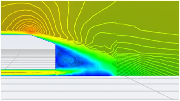
Q3. Explain the significance of the point of separation.
- The point of separation defined by the Ahmed body and the flow, the alpha angle depending on which value is at it causes change in flow direction, forces required, lift on the body, induced drag due to "tip vortex", at a critical value flow in slant stalls and reduced lift-reducing as well drag, all depending on the value of alfa and the Reynolds numbe