Week 8 - Simulating Cyclone separator with Discrete Phase Modelling
Aim:- To perform analysis on cyclone separator and calculate the separation efficiency and pressure drop.
Introduction:- Cyclones are devices that employ a centrifugal force generated by a spinning gas stream to separate particles from the carrier gas. Their simple design, low maintenance costs, and adaptability to a wide range of operating conditions such as sizes and flow rates make cyclones one of the most widely used particle removal devices. By using suitable materials and methods of construction, cyclones may be adapted for use in extreme operating conditions: high temperature, high pressure, and corrosive gases. Cyclones are important particle removal devices in both engineering and process operations.
Theory of the topic:- Cyclones are devices that employ a centrifugal force generated by a spinning gas stream to separate particles from the carrier gas. Their simple design, low capital cost and nearly maintenance-free operation make them ideal for use as precleaners for more expensive final control devices such as bag30 houses or electrostatic precipitators. Cyclones are particularly well suited for high temperature and pressure conditions because of their rugged design and flexible component materials. Cyclone collection efficiencies can reach 99% for particles bigger than 5 µm [5], and can be operated at very high dust loading. 35 Cyclones are used for the removal of large particles for both air pollution control and process use. Application in extreme conditions includes the removal of coal dust in a power plant and the use as a spray dryer or gasification reactor.
Engineers are generally interested in two parameters in order to carry out an assessment of the design and performance of a cy- 40 clone. These parameters are the collection efficiency of particle and pressure drop through the cyclone. An accurate prediction of cyclone efficiency is very important because an inaccuracy in the efficiency prediction may result in an inefficient design of the cyclone separator. CFD has a great potential to predict the 45 flow field characteristics and particle trajectories inside the cyclone as well as the pressure drop [6]. The complicated swirling turbulent flow in a cyclone places great demands on the numerical techniques and the turbulence models employed in the CFD codes when modeling the cyclone pressure drop. 50 This study presents an application of computational fluid dynamics, in the prediction of cyclone efficiency. This study also reviews the prediction of four different empirical models for cyclone efficiency, namely Lapple [1], Koch and Licht [2], Li and Wang [3], and Iozia and Leith [4].
1)Iozia and Leith
(1990) logistic model is a modified version of Barth (1956) model which is developed based on force balance. The model assumes that a particle carried by the vortex endures the influence of two forces: a centrifugal force, Z, and a flow resistance, W. Core length, zc , and core diameter, dc , are given as
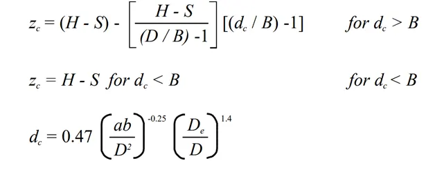
The addition made by Iozia and Leith on the original Barth (1956) model are the core length zc and slope parameter β expression which is derived based on the statistical analysis of experimental data of cyclone with D = 0.25 m. The collection efficiency ηi of particle diameter dpi can be calculated from
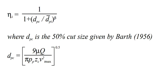
2) LI AND WANG MODEL
The Li and Wang (1989) model includes particle bounce or re-entrainment and turbulent diffusion at the cyclone wall. A two-dimensional analytical expression of particle distribution in the cyclone is obtained. Li and Wang model was developed based on the following assumptions: • The radial particle velocity and the radial concentration profile are not constant, for uncollected particles within the cyclones. • Boundary conditions with the consideration of turbulent diffusion coefficient and particle bounce re-entrainment on the cyclone wall are:
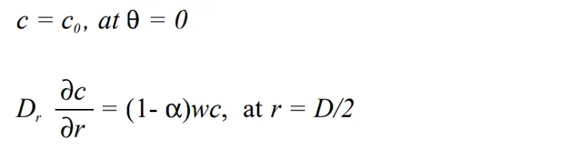
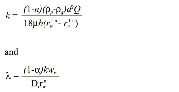
The tangential velocity is related to the radius of cyclone by: uRn = constant. The concentration distribution in a cyclone is given as:
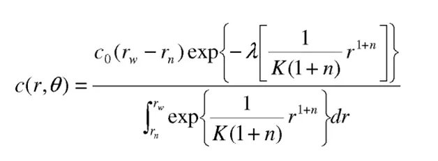
Where
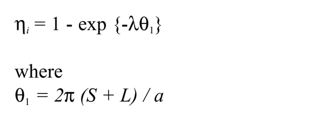
The resultant expression of the collection efficiency for particle of my size is given as
3) KOCH AND LICHT MODEL
Koch and Licht (1977) collection theory recognized the inherently turbulent nature of cyclones and the distribution of gas residence times within the cyclone. Koch and Licht describe particle motion in the entry and collection regions with the additional following assumptions:
- The tangential velocity of a particle is equal to the tangential velocity of the gas flow, i.e. there is no slip in the tangential direction between the particle and the gas.
- The tangential velocity is related to the radius of cyclone by: uRn = constant. A force balance and an equation on the particles collection yields the grade efficiency ηi.
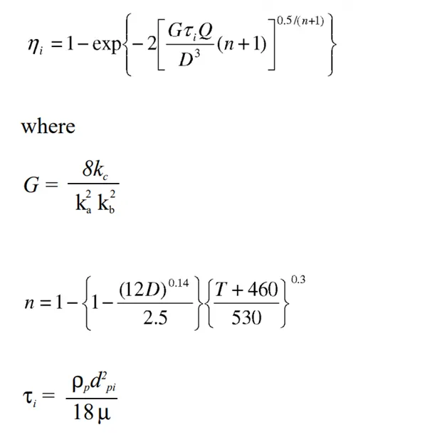
G is a factor related to the configuration of the cyclone, n is related to the vortex and τ is the relaxation term.
4)LAPPLE MODEL
Lapple (1951) model was developed based on force balance without considering the flow resistance. Lapple assumed that a particle entering the cyclone is evenly distributed across the inlet opening. The particle that travels from inlet half width to the wall in the cyclone is collected with 50% efficiency. The semi empirical relationship developed by Lapple (1951) to calculate a 50% cut diameter, dpc, is
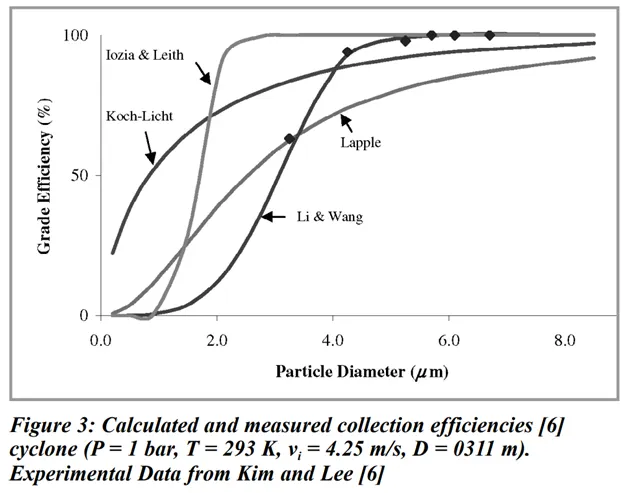
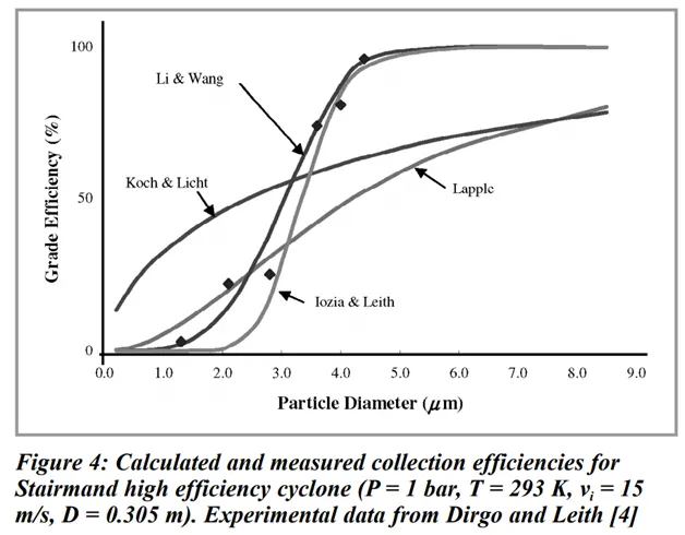
Iozia and Leith [4] logistic model predicted satisfactory the efficiency for cyclone of diameter 0.4 and 0.305 m as shown in Figures 2 and 4. For smaller cyclone diameter, the prediction of Iozia and Leith model [4] is not satisfactory. It considerably overestimates the grade efficiency for D = 0.0311 and 0.058 m as shown in Figures 3 and 5. The reason of this disagreement maybe caused by the generalised form of core length, zc in Iozia and Leith model which is developed based on the statistical analysis of experimental cyclone data from cyclone of D = 0.25 m. Therefore, the prediction of the model is only satisfactory for cyclone diameter around this range.
Solving & Modelling approach
- Geometry
In geometry section we can create or also import the geometry file in SPACECLAIM.
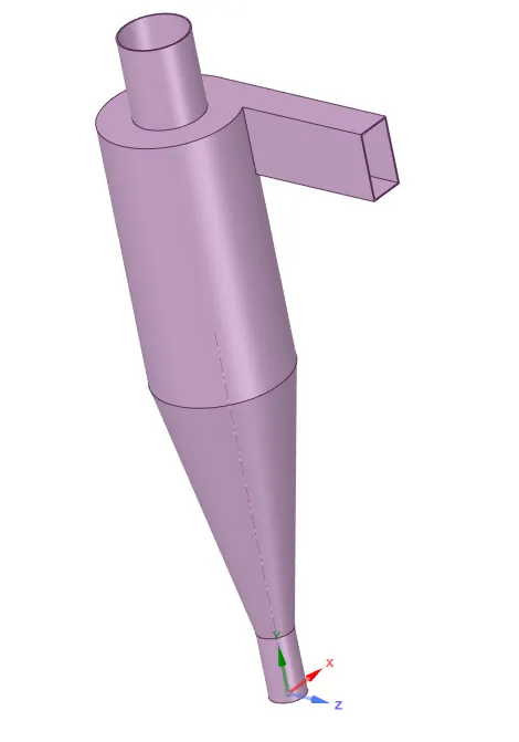
After importing the geometry file we have to extract the volume part where we have to perform the simulation.
This process is done with the help of volume extraction tool and by using selecting edges method we can extract easily.

After extraction we have to suppress the geometry part then it have only volume part
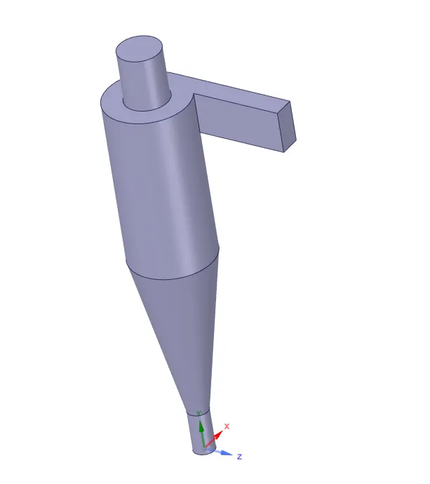
Here our geometry part has finished.
- Meshing section
In this section our aim to create a fine mesh so we have to put input like element size and which method we will used here we use cartesion method.
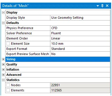
After putting input of mesh then hit on update mesh.
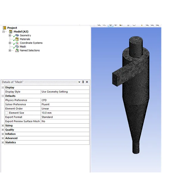
Then check the mesh quality.

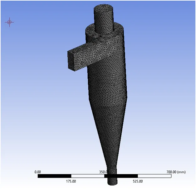
And final mish is look like this (BELOW FIG)
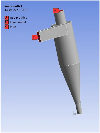
After create mesh we have to put the name on side of geometry. By selecting face selection option.
- Setup section
In this section we are able to put all input of our simulations.
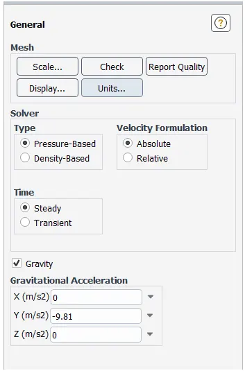
General setting:- here pressure based solver, absolute velocity and steady time and here we also use gravity force and put the value of g is -9.81 .
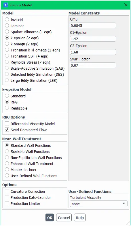
Then we have to setup viscous model here we use k-epsilon with RNG model and in RNG option we use swirl dominated flow option as we know our simulation is fully based on swirl of fluid that’s why we use this option. And lastly we use standard wall functions.
Discrete phase model A discrete phase model (DPM) is used when the aim is to investigate the behavior of the particles from a Lagrangian view and a discrete perspective. In fact, the difference between the Lagrangian and the Eulerian view is that fluid behavior in Lagrangian view is examined on the basis of a particle tracking of a particle of fluid flow; Whereas fluid behavior is considered in Eulerian view based on the assumption of a finite volume element in the fluid flow path.
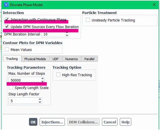
If the behavior of discrete particles in the presence of a continuous flow field is affected by continuous flow, the interaction with the continuous phase must be activated. Also, if the particle tracking is relatively unsteady over time, the unsteady particle tracking option must be activated. The discrete phase can be applied in various physical forms, the type of which depends on the problem model. One of the physical defining modes is the two-way turbulent coupling mode, which is used to study the effects of changes in the turbulent quantities caused by particle damping and Eddy turbulence.
Injection Also, the injection process for the mixed flow is defined in the input section of the model. In this way, in the input section of the model, the desired material enters the interior space of the model with the same discrete state or particle by particle. This particle injection as a discrete state can occur in different states. For example, the combusting mode is used when the material is injected into the model’s interior to perform the combustion process.
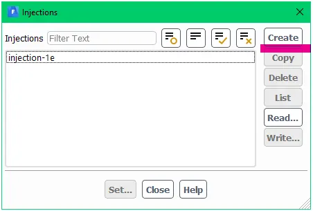
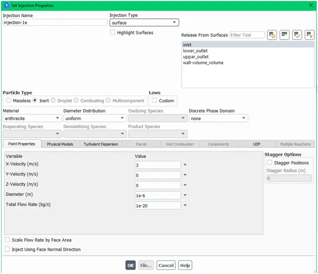
Set injection property here we can set which type of particle is injected in the cyclone separator here we use anthracite particle as a material and diameter of each and every single particle is uniform and surface injection type and the particle material is enter in the separator from inlet side. And finally we have to setup the inlet velocity that is 3m per second from inlet.
Now we have to input boundary condition
1st inlet condition
Here our velocity is same as we put in injection property of DPM which is 3 meter per second
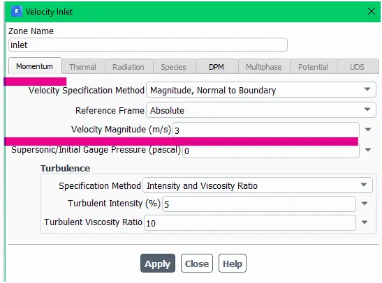
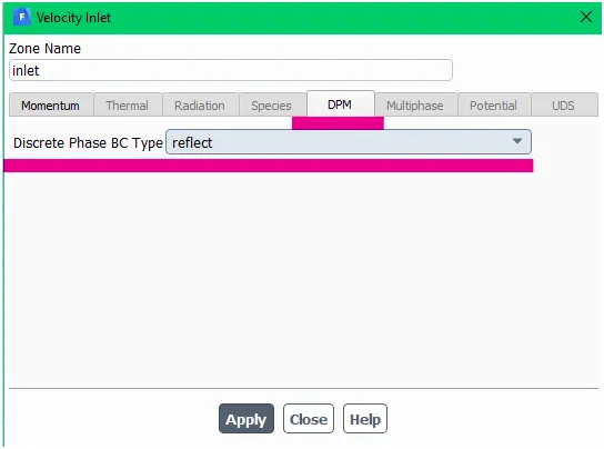
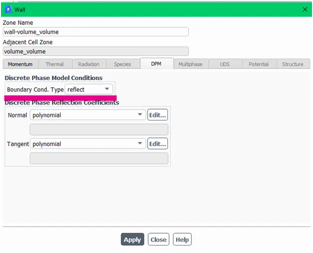
And discrete phase model of inlet condition is reflect.
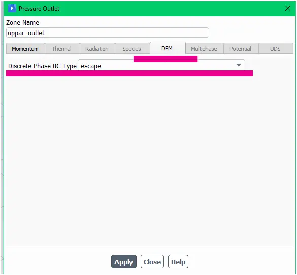
DPM of upper outlet is escape
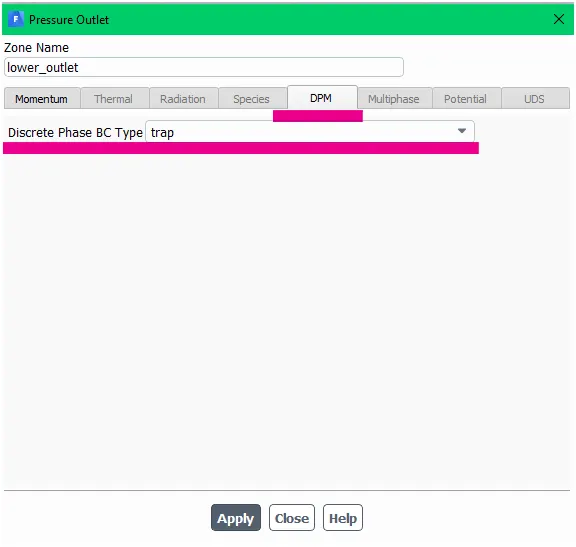
DPM of lower outlet is trap
DPM of wall is reflect
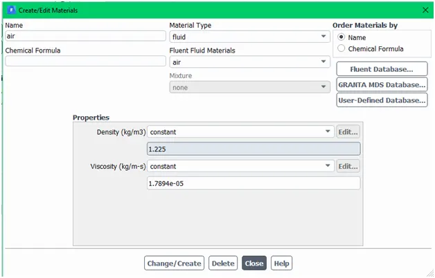
Here we use air as a fluid
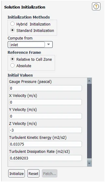
After set all input we have to initialize the whole setup
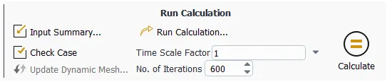
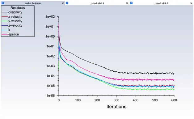
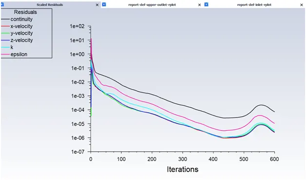
Then hit the calculation option for 600 iterations.
After calculation is completed the result is shown below.

Case 1
Here we performed this simulation is only for 1μm diameter but we have to perform more simulation for different diameters so the all setup is done in above simulation is same here we will change only diameter of particle.
|
Diameter of particle |
Velocity at inlet |
|
1μm |
3m/sec |
|
2μm |
3m/sec |
|
3μm |
3m/sec |
|
4μm |
3m/sec |
|
5μm |
3m/sec |
Trapped particle
Separation efficiency = ---------------------------------------- * 100
Tracked particle
- For 1μm of diameter of particles
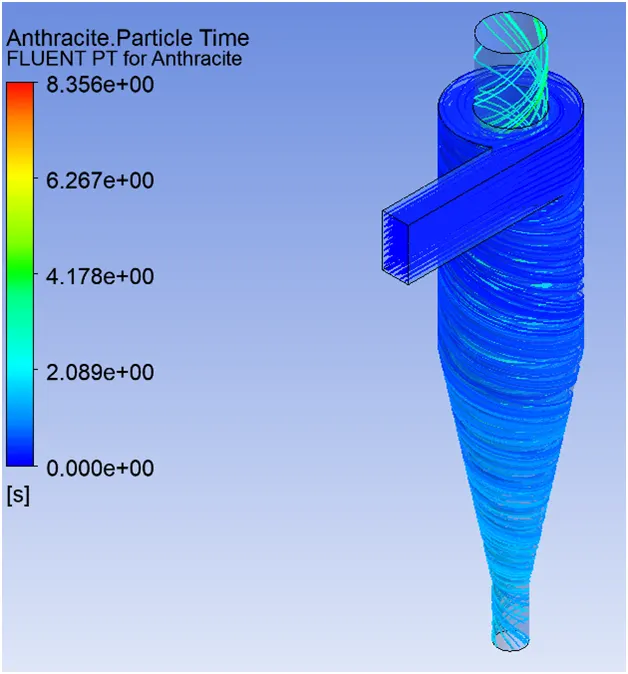
Separation efficiency 17%
- For 2μm of diameter of particles .

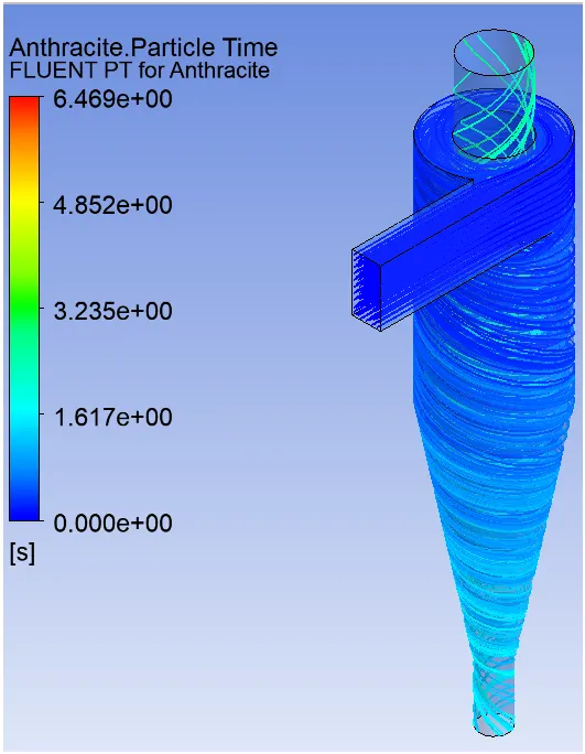
Separation efficiency 75%
- For 3μm of diameter of particles
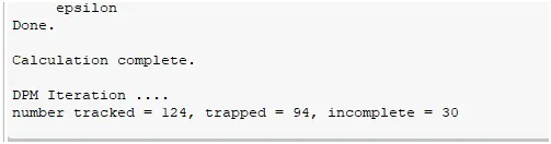
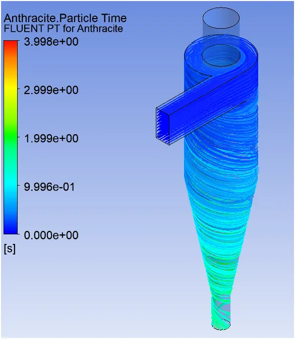
Separation efficiency 75%
- For 4μm of diameter of particles

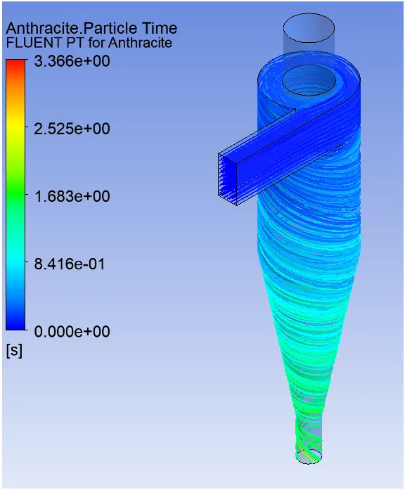
Separation efficiency 76%
- For 5μm of diameter of particle

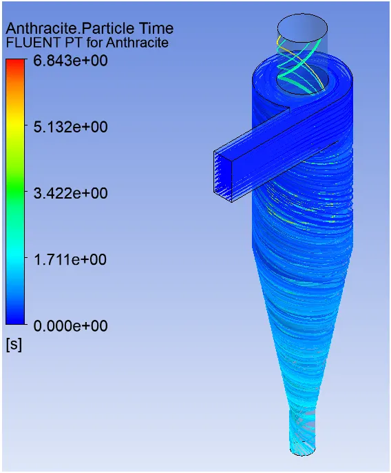
Separation efficiency 79%
|
Diameter of particle |
Velocity at inlet |
Separation efficiency |
|
1μm |
3m/sec |
17% |
|
2μm |
3m/sec |
75% |
|
3μm |
3m/sec |
75% |
|
4μm |
3m/sec |
76% |
|
5μm |
3m/sec |
79% |
As we show in table when diameter of particle is increases then the separator efficiency is also get increased and after 2μm diameter of particle the efficiency of cyclone separator is increasing but in slightly manner so from here we can say that particle from 3μm is easily separated in cyclone separator
Case 2
Here we change the velocity from 1m/sec to 5m/sec and diameter of particle is 5μm remain same for all simulation as we shown below table.
|
Velocity at inlet |
Diameter of particle |
|
1m/sec |
5μm |
|
2m/sec |
5μm |
|
3m/sec |
5μm |
|
4m/sec |
5μm |
|
5m/sec |
5μm |
Trapped particle
Separation efficiency = ---------------------------------------- * 100
Tracked particle
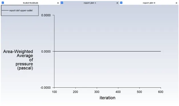
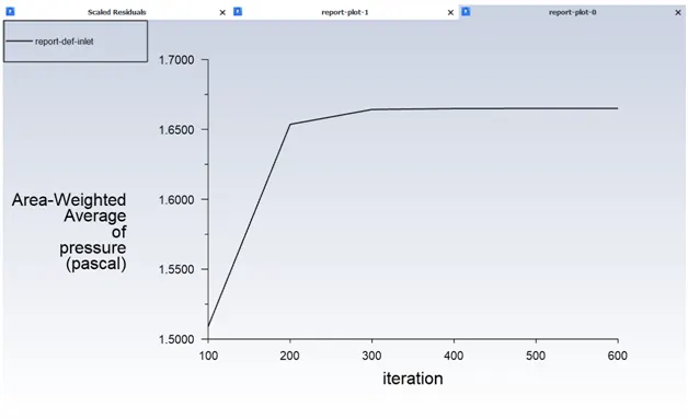
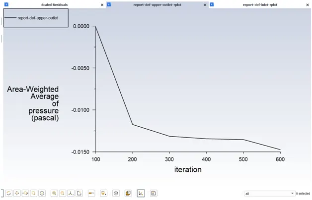
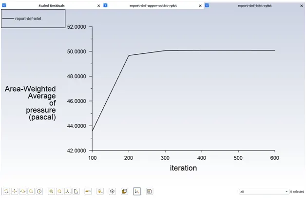
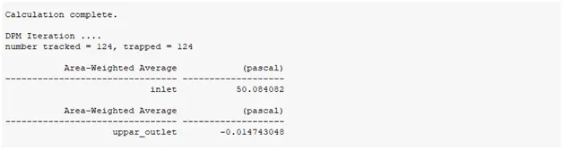
Pressure drop =pressure at inlet – pressure at outlet
- Velocity at inlet is 1m/sec and diameter of particle is 5μm
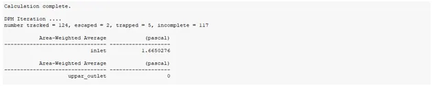
Separation efficiency = 4.03%
Pressure drop = 1.6650
- Velocity at inlet is 2m/sec and diameter of particle is 5μm
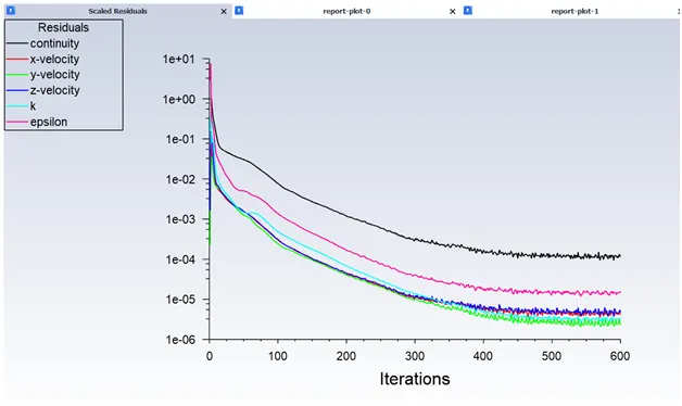
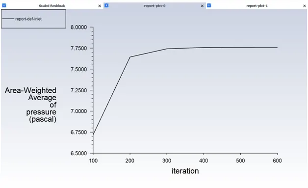
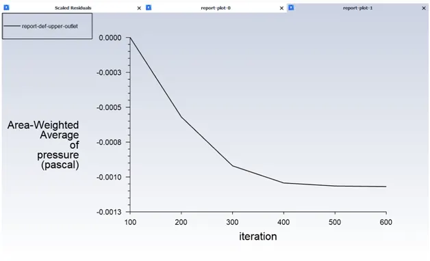
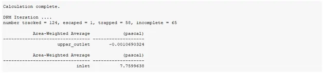
Separation efficiency = 46.77%
Pressure drop = 7.761032832
- Velocity at inlet is 3m/sec and diameter of particle is 5μm
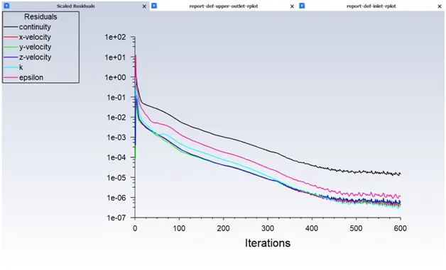
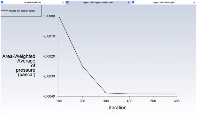
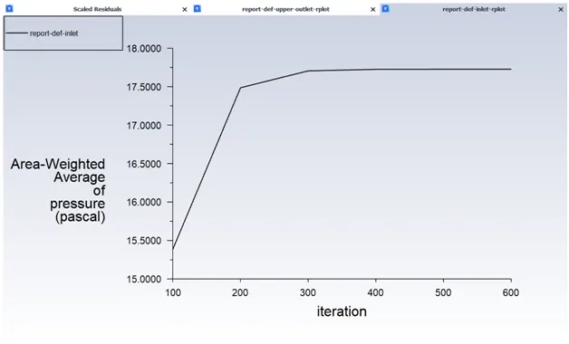
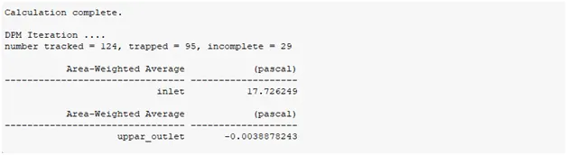
Separation efficiency = 76.61%
Pressure drop = 17.73013682
- Velocity at inlet is 4m/sec and diameter of particle is 5μm
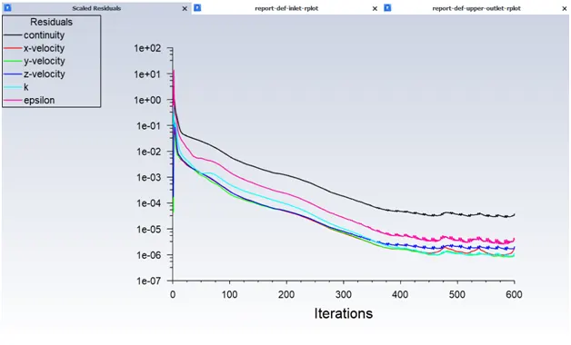
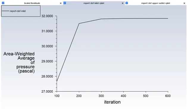
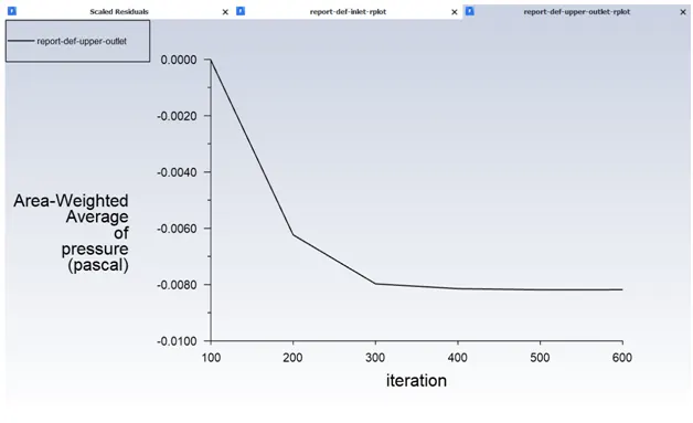
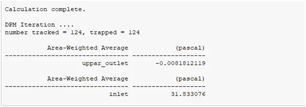
Separation efficiency = 100%
Pressure drop = 31.84125721
- Velocity at inlet is 5m/sec and diameter of particle is 5μm
Separation efficiency = 100%
Pressure drop = 50.09882505
|
Velocity at inlet |
Diameter of particle |
Efficiency % |
Pressure drop |
|
1m/sec |
5μm |
4.03 % |
1.6650 |
|
2m/sec |
5μm |
46.77 % |
7.761032832 |
|
3m/sec |
5μm |
76.6 % |
17.73013682 |
|
4m/sec |
5μm |
100 % |
31.84125721 |
|
5m/sec |
5μm |
100 % |
50.09882505 |
We can see from tables that in Case 1, efficiency of separation increases with particle diameter and in Case 2, with increment of Velocity
- Also we can observe that in Case 1, Separation efficiency increases in gradual manner with increase in particle diameter.
But in Case 2, separation efficiency increases rapidly with increase in velocity. It is because the Pressure Drop has more impact in cyclone separator efficiency.
- In Case 1, particle resident time decrease with increase in particle Diameter.
- In Case 2, particle resident time decrease with increase in particle Velocity
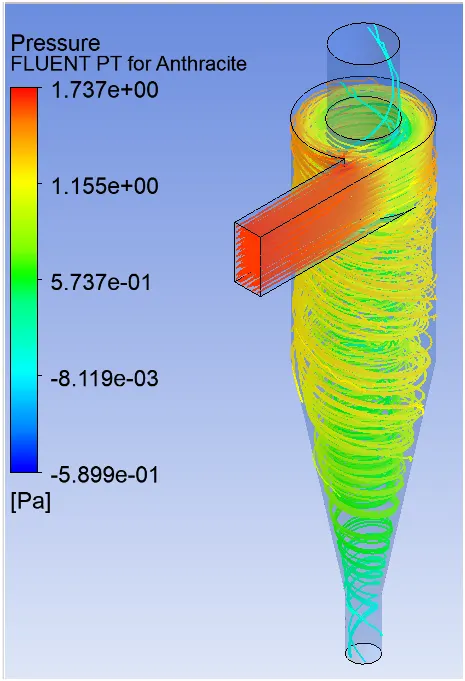
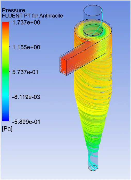
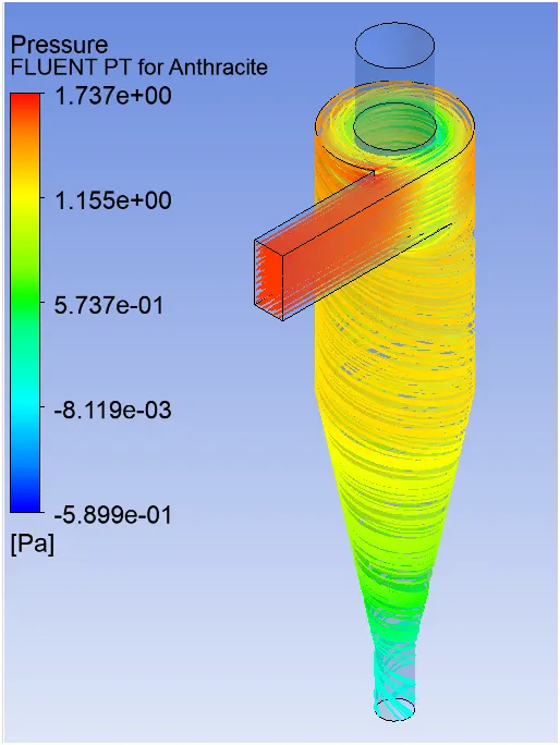
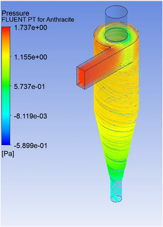
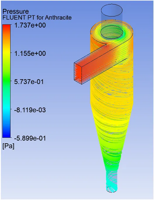
- We can see from the Pressure contour in all cases that Velocity is high at the inlet, because the Particle are being injected forcefully by the inlet.
• Also Pressure is high at the inlet and at the outlet surface of the low at the axial portion, because when particles travels in a swirl motion, they are being imparted on the outer surface of cyclone. So most of the Particles are thrown from axial to radial direction and due to that pressure at the outlet surface will always be high.
Conclusion
- We can conclude that Separation Efficiency of cyclone separator depends on both Diameter of particles and also on the velocity of the particles.
- Higher velocity is more effective for higher efficiency.
- Higher efficiency of cyclone separator has highest pressure drop.
- Higher the velocity, higher the pressure drop and highest the efficiency.
- With increase in Diameter of Particles and velocity of particle, particle resident time decreases.
- So less resident time taken by particle results in higher efficiency of cyclone separator.