Week 10 - Simulating Combustion of Natural Gas.
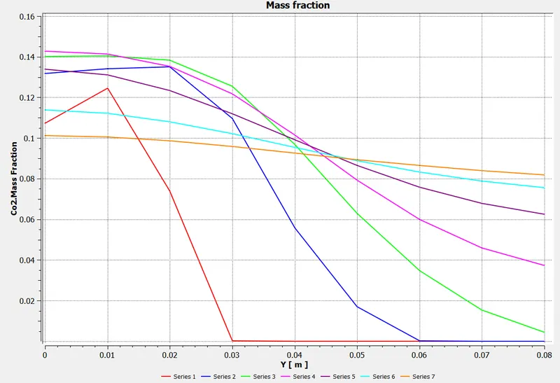
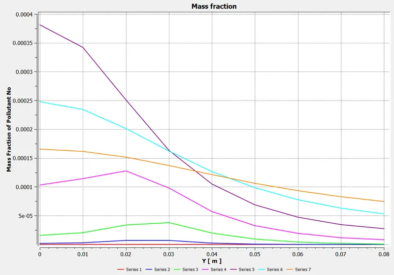
Aim : To perform a combustion simulation on the combustor model and plot the variation of the mass fraction of the different species.
Objective :
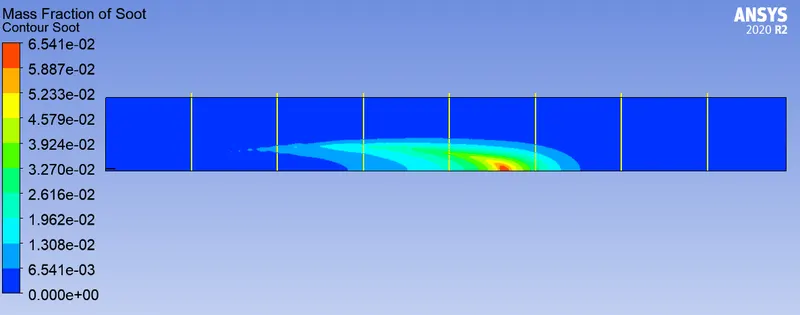
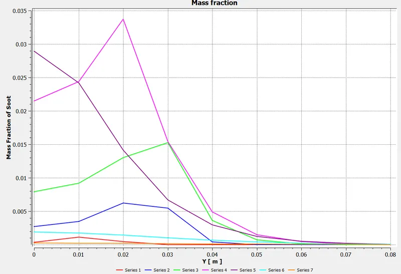
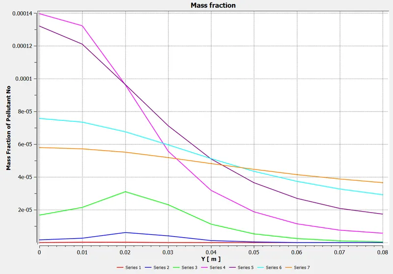
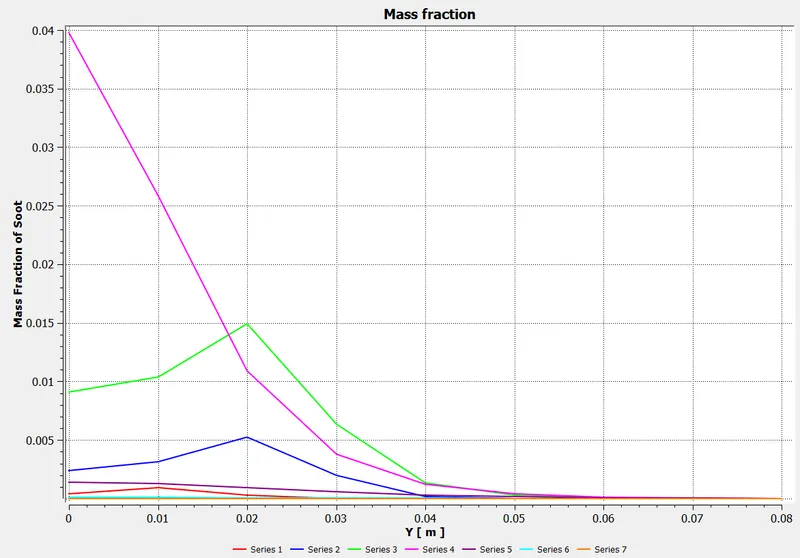
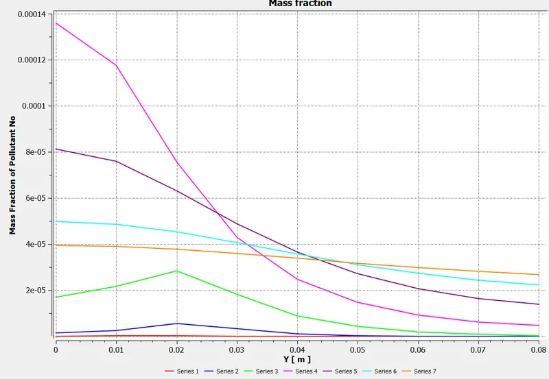
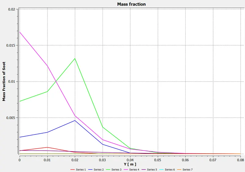
- Using line probes at different locations of the combustor to plot for CO2, H2O, CH4, N2, O2, NOx emissions & Soot formation.
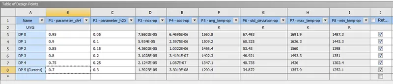
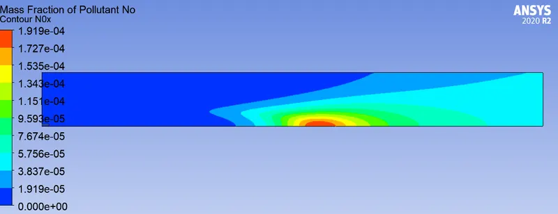
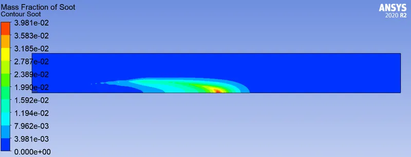
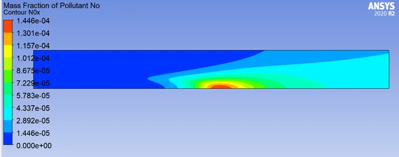
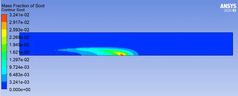
- To check the effect of adding the water in the fuel from 5% to 30% by mole and observe the effect of it on the Nox and soot is getting formed at the outlet of the combustor.
Introduction :
The emission of particulate matter, or soot, can be considered a side effect associated to combustion processes characterized by high temperature and rich conditions. The production of these carbon nanoparticles entails a reduction in the efficiency of combustion device, as well as determental effect on climate change and human health. Therefore drastic reduction in emmision is mandatory, demanding for deeper understanding in the formation of process.which is still an open issue in combustion chemistry research.
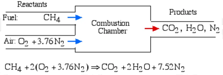
Stoichiometric combustion of methane (Natural Gas) in atmospheric air -
Species transport equation - Using this governing eqn. Fluent can model mixing & transport of chemical species by solving conservative equations describing convection,diffusion and reaction sources for each component species.

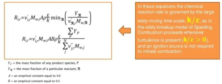
Eddy dissipation model - based on the work of Magnussen and Hjertager, is a turbulent-chemistry reaction model. Reaction rates are assumed to be controlled by turbulence, ignoring the effect of chemistry timescale.
In EDM the net rate of production of species(i) due to reaction (r), is given by
Solution & Modeling aprroach -
Geometry -
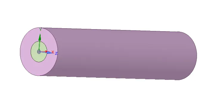
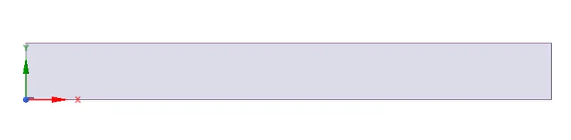
- 3D model imported to space claim & splited or removed 3/4th of body to get a Axi-symmetry sectional plane along X-Y plane and copied to new model file.
- Now this 2D combustor model having outer side surface of fuel Inlet thick pipe is combined using tool.
Meshing-
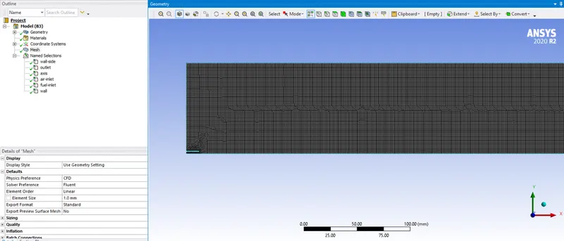
- 1mm global size meshing done and Hexa elements was formed.
- Capture curvature enabled.
total no. of elements = 67423
Setup-
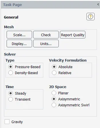
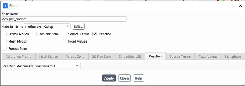
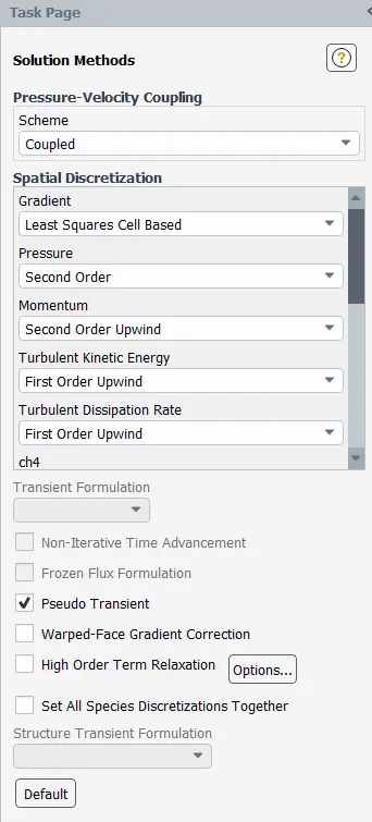
- Axisymmetric 2D space is turned On and steasy state analysis is done,as we are interested an uniform temperature distribution at outlet.This type a scenario can be easily achived from Turbulence chemestry interaction model using 'Eddy dispation model'. where fuel burning is governed by energy source but for turbulence.
- Here K & eplison should be high enough providing characteristic turbulence time scale from which ansys fluent calculates combustion time resulting faster desired results.(less computational time)
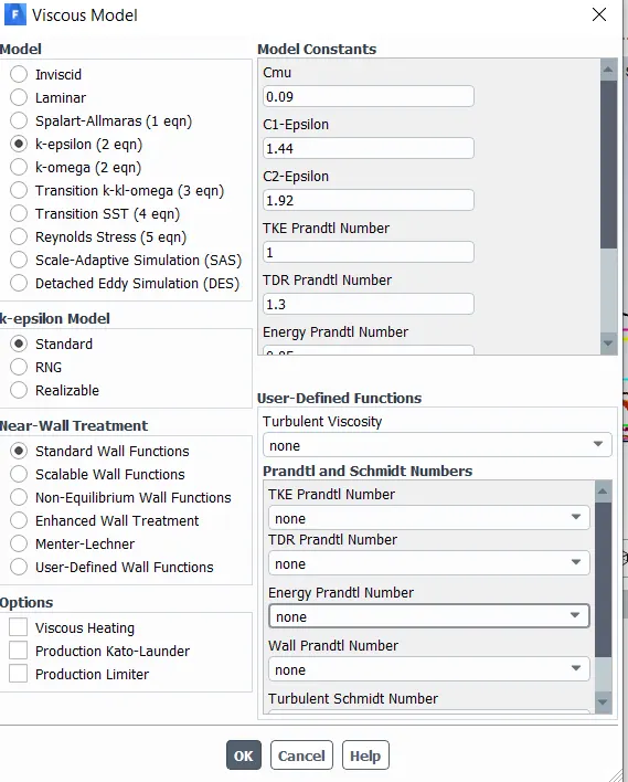
- Energy is turned On and K-epsilon model is preffered in this type of case, enabling this will alow eddy-dispation model.
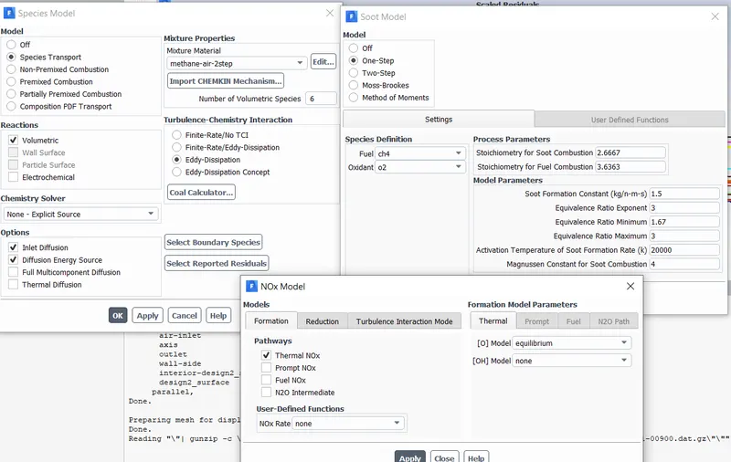
- In species model 'Transport' is tuned On and Volumetric reaction type is enabled as reactions takes place in Gas phase.
- Later checked on for Inlet diffussion & Diffussion energy source,because by default in pressure based solver diffusion coeffient are not included at Inlet.
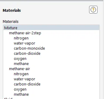
- Methane-air-2step mixture is used, which allows to add water(h20) in thier mixture properties.
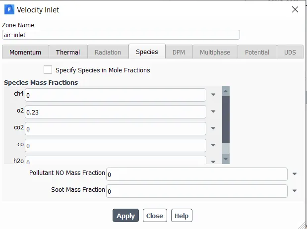
- Boundary condition -
Air-Inlet : Velocity = 0.5m/s ; temp = 300k ; In species mass fraction O2 = 0.23 (23%)
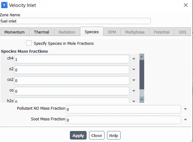
Fuel Inlet : Velocity = 80m/s ; temp = 300k ; In species mass fraction CH4 = 1 (100%)
Outelt : Presure outlet = 0 pa
Walls : temp = 300k.
- Hybrid Intialization is done.
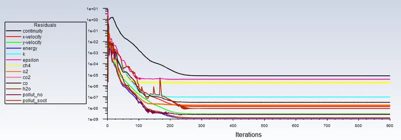
- Simulation run for 900 iterations and found that residuals converged at 250 iterations.
Part -1
Results -
Residuals
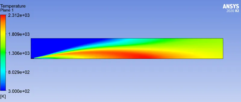
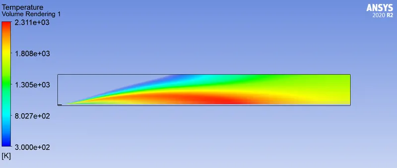
Temperature contour -
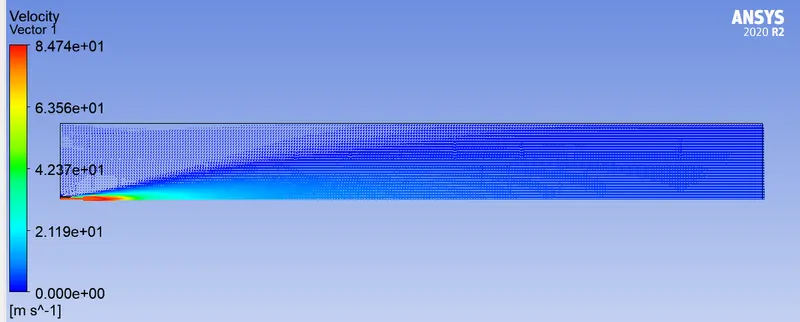
Velocity vector contour -
Mass fractions :
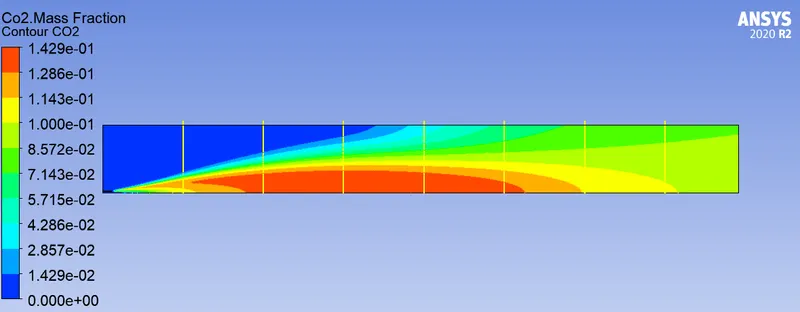
Co2
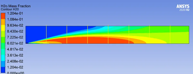
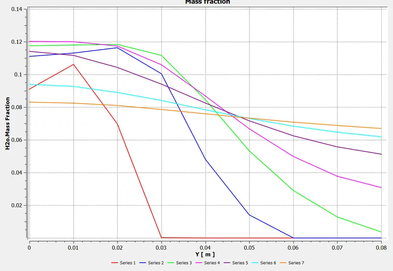
H20
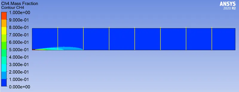
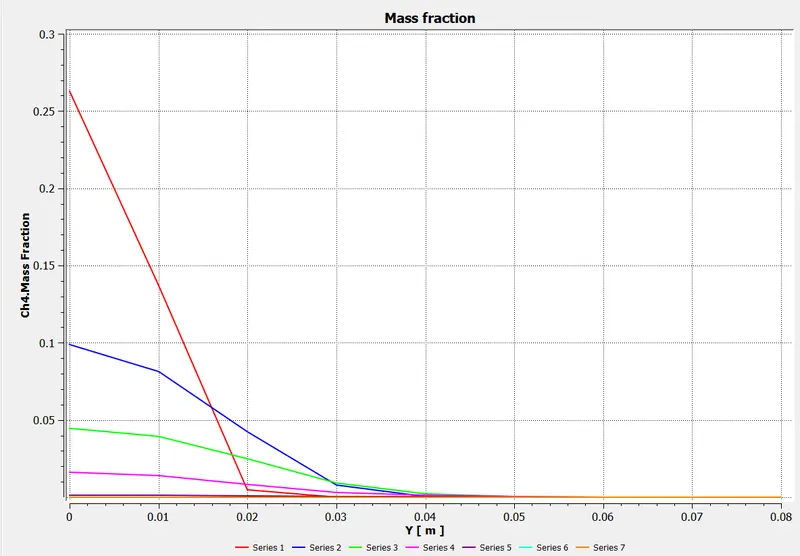
CH4
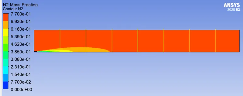
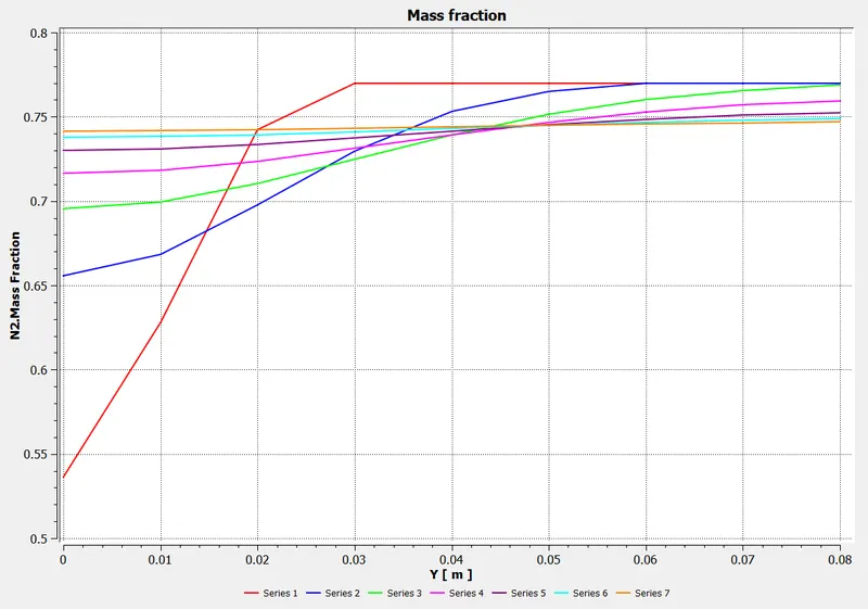
N2
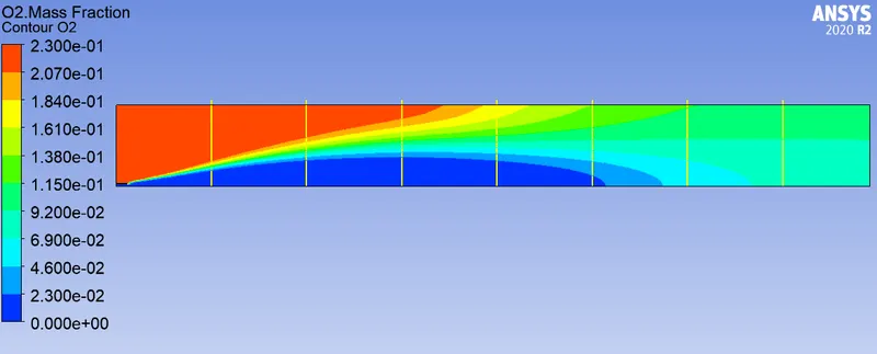
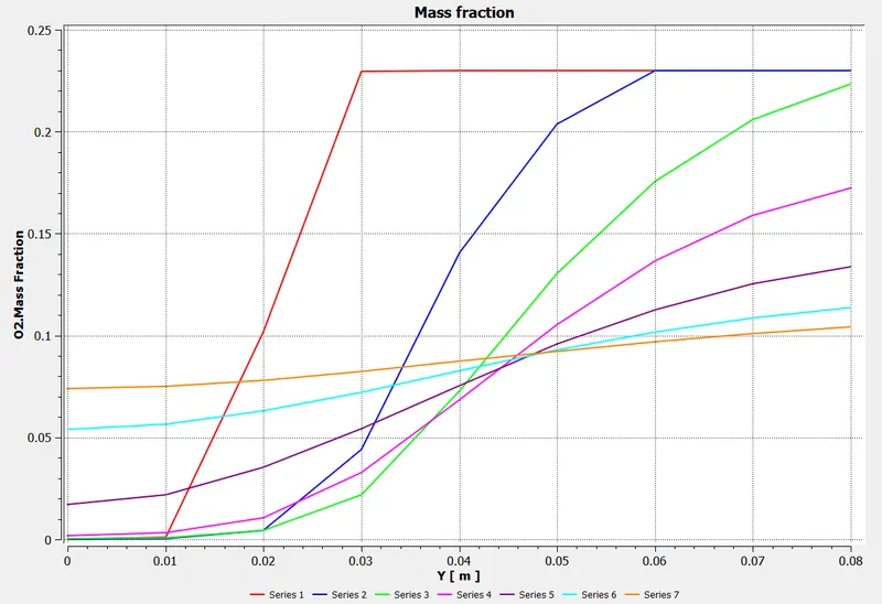
O2
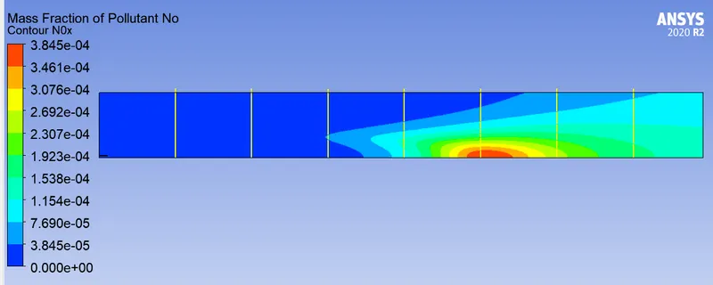
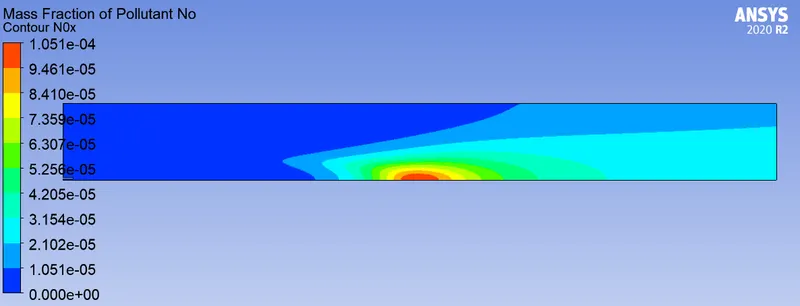
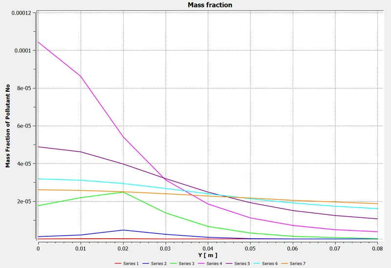
Nox
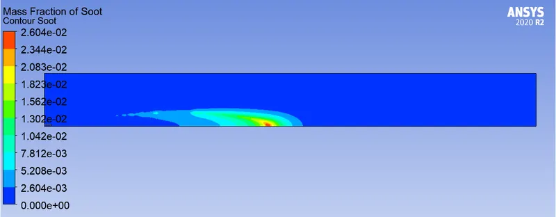
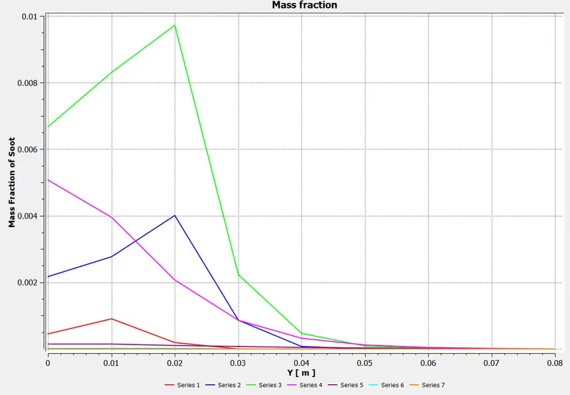
Soot
Part -2
Setup-
- In species Fuel Inlet BC , H20 is added in terms of % mass fraction from 5% to 30%.
- By changing CH4 & H20 mass fraction from constant to parameter, design points are added in the parametric window.
Results -
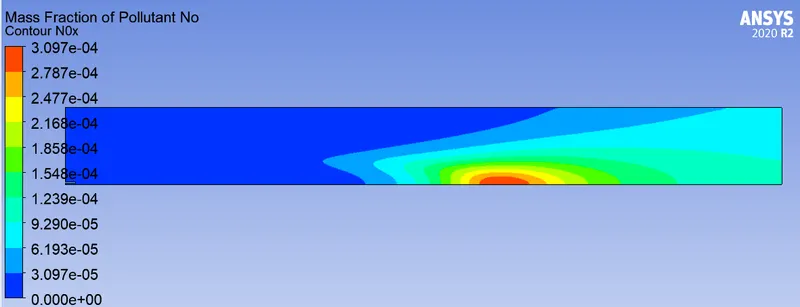
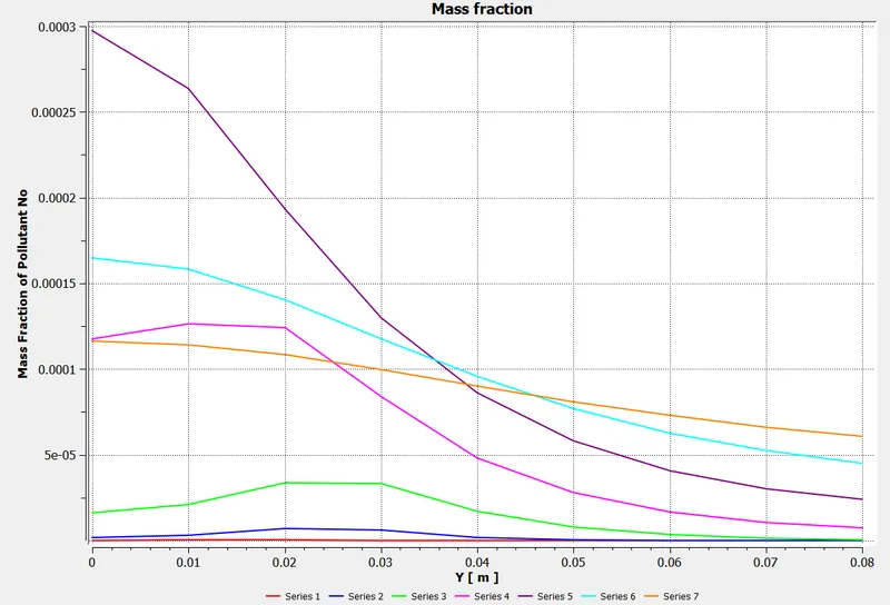
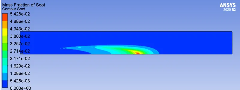
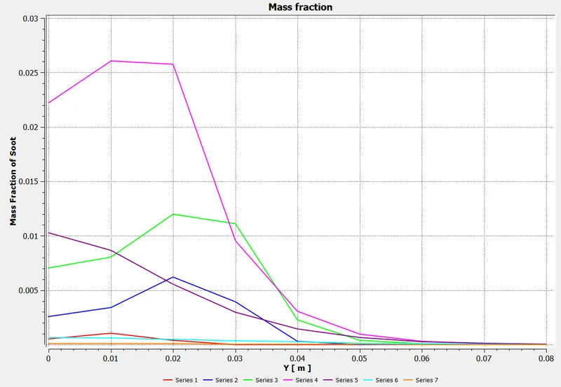
Case1-DP0 : CH4=95%, H20=5%
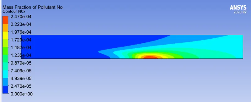
Nox
Soot
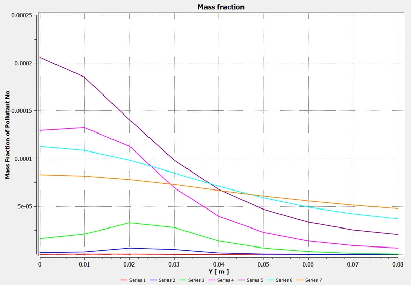
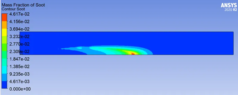
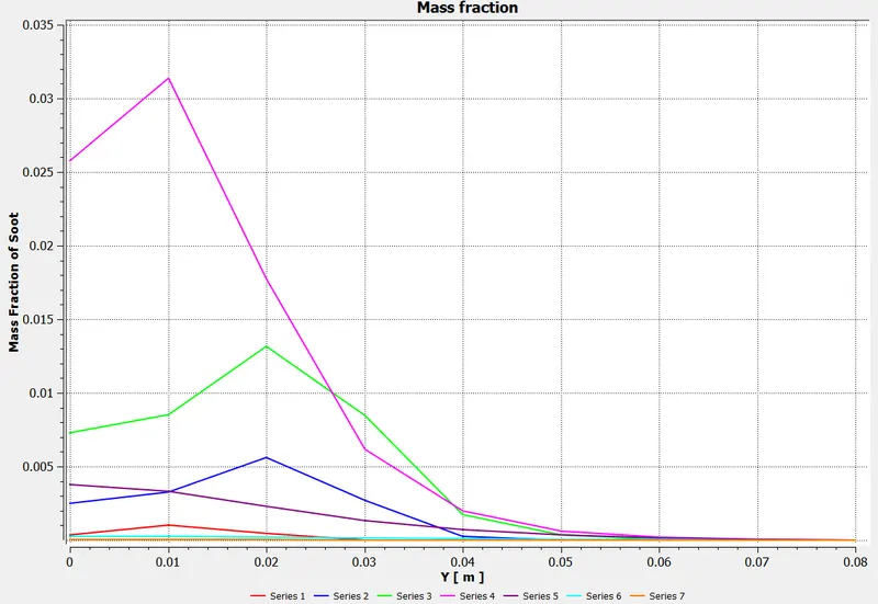
Case2-DP1 : CH4=90%, H20=10%
Nox
Soot
Case3-DP2 : CH4=85%, H20=15%
Nox
Soot
Case4-DP3 : CH4=80%, H20=20%
Nox
Soot
Case5-DP4 : CH4=75%, H20=25%
Nox
Soot
Case6-DP5 : CH4=70%, H20=30%
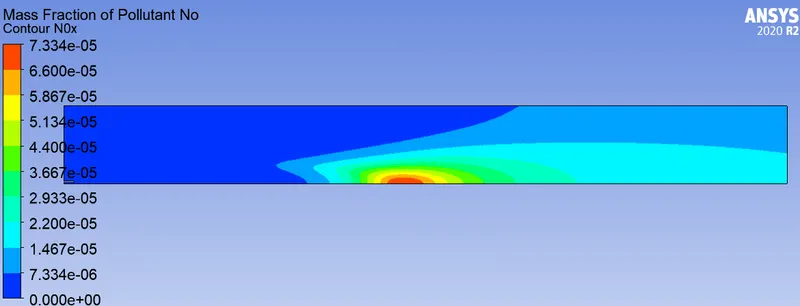
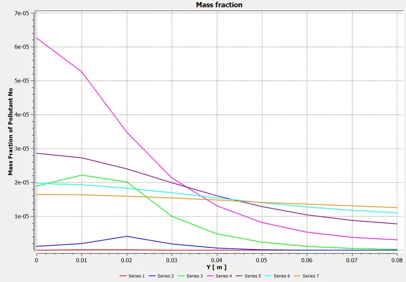
Nox
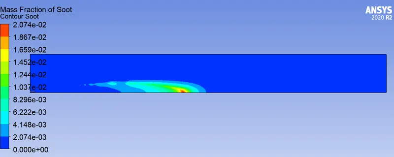
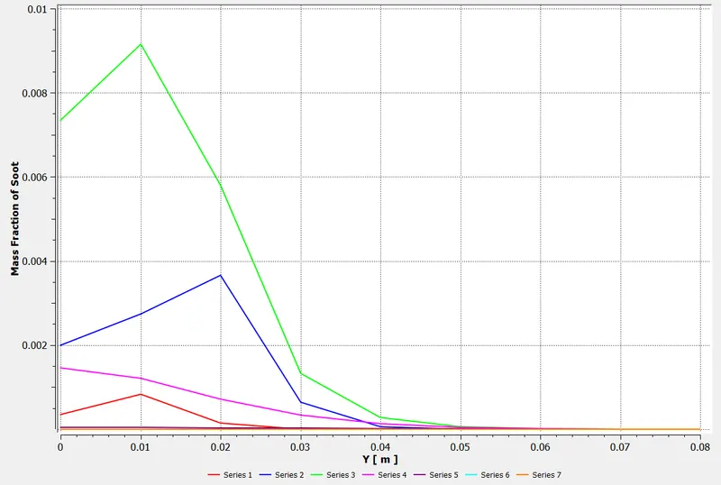
Soot
Comments -
- There are several methods to reduce Nox & soot, one of them is addion of water in fuel.
- Nox : There is no much major variation observed in Nox mass fraction contours but seen decrease in outlet.
- Soot : We can observe from the above numerical cases that consideribly reducion in soot with increase in water%. Also the soot mass fraction contours length is reduced significantly.
- Temperature : After 15% std. deviation of temperature reduced and min temp. also fell down.