Week 10 - Simulating Combustion of Natural Gas.
AIMS
The aim of the challenge is to simulate the combustion of naural gas in an IC Engine.
OBJECTIVES
- To import the combustor 3D model in Spaceclaim, convert it into 2D ad save it as new model.
- To mesh the combustor model with suitable mesh setting.
- To setup the solver setting with proper solver model and its parameter.
- To generate plots of mass fraction of in combustion species -CO2, H2O, O2, N2, CH4, NOx and soot formation.
THEORY
Natural gas, colourless highly flammable gaseous hydrocarbon consisting primarily of methane and ethane. Natural gas is one of the major combustion fuels used throughout the globe. Natural gas combustion is an exothermic chemical reaction in which natural gas and oxygen react, producing heat and several chemical byproducts. Byproducts of combustion are a concern, albeit It is certainly cleaner than burning many fossil fuels. To study combustion of natural gas CFD is used, by simulating combustion mixing of fuel and air, temperature rise, flame propagation, byproduct properties etc can be predicted. In this study we will simulate natural gas combustion and find byproduct fractions with effect of mixture of water and fuel as inlet, on soot formation.
The constant increase of world energy consumption, that represents a crucial challenge for researchers and scientists. Mostly, fossil fuel under goes some type of combustion and produce energy and byproducts. Obnoxity of emission is a main concern today because is it raising the global average temperature. Nox is one of the most dangerous byproduct, to limit it, water can be mixed during the combustion of natural gas. In this study we will study the effect of water quantity at inlet, on mass fraction of NOx and soot formation.
Combustion is a very complex process because it involves large number of chemical reactions, which will have multiple steps in their mechanism. CFD software makes this task easy, it provides several models like eddy dissipation, finite rate chemistry, finite rate eddy dissipation model etc. to find source of combustion in no time and as a result it allows you to plot mass fraction plots, contours of temperature and velocity, which is very helpful to visualize flame propagation, hot spot etc.
Flames can be divided into two types premixed flame and non-premixed(diffusion) flames. These further divided into laminar and turbulent.in premixed fuel and air mixed homogenously before combustion. In non-premixed fuel and air meet during combustion. When a self-sustainable flame propagates at subsonic velocities then flame is called as laminar flame. Turbulent flame is just opposite to that, most of the combustion device produces turbulent flames. In this study we are assuming that turbulent flame will rise during natural gas combustion. Also, there is no energy source which incites combustion, Burning is starting by turbulence.
Through the combustion process we follow one reaction that drives the simulation in back ground which is the combustion reactiongiven below.
`CH_4+2(O_2+3.76N_2)-> CO_2+2H_2O+7.52N_2`
This reaction is used to calculate the mole fractions and mass fractions used in the simulation.
GEOMETRY
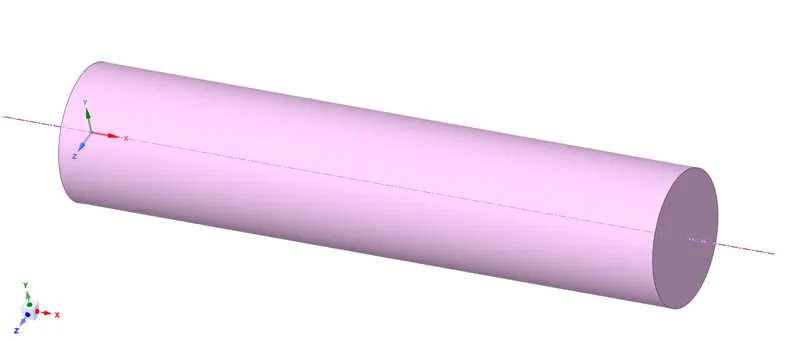
The geometry shown below is 2 chambered combustion set up where we have small sot between air inlet and fuel inlet . We loaded this 3D geometry into space claim and then we cut this geomtery with two planes. Used split command to split 3 quandrants. Later utilized the combine command to join different zones in the geometry and copied the 2D geometry in XY plane and pasted to new file
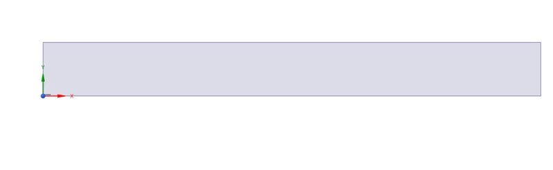
The 2D geometry created from the 3D has shown below. The geometry is extracted in XY plane such that the axis of the geometry should be on X axis in order to perform an asymetrical simulation in fluent.
MESH
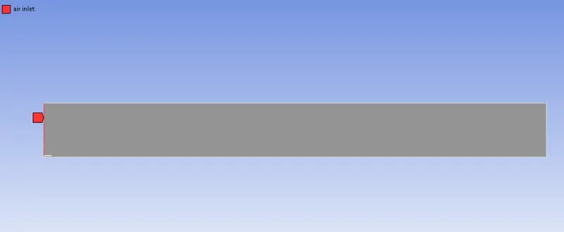
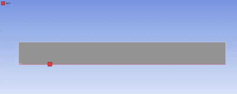
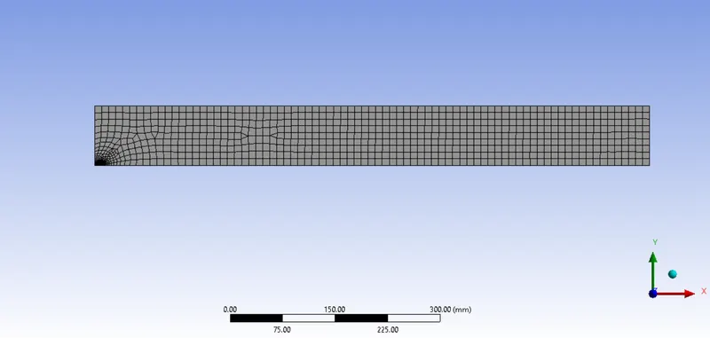
Model was imported from Spaceclaim and tia mesh was deployed with element size 1mm. Named selection was created like fuel inlet, air inlet, wall etc, these used for boundary conditions in solver setup. The locations of the boundaries are given below
air inlet :
axis:
fuel inlet:

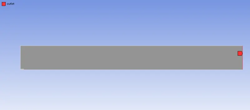
outlet:
The figure below is the mesh used for the simulation of natural gas in combustion.
SETUP AND RESULTS
Started with general setting we proceeded with pressure based steady state solver, because fluid flow velocity is very low. In 2D space axisymmetric was chosen due to symmetricity.
Realizable K-epsilon with standard wall functions chosen as solver model, for this simulation flow near wall was not major concern. K-omega produces best result in analysis of fluid flow near wall.
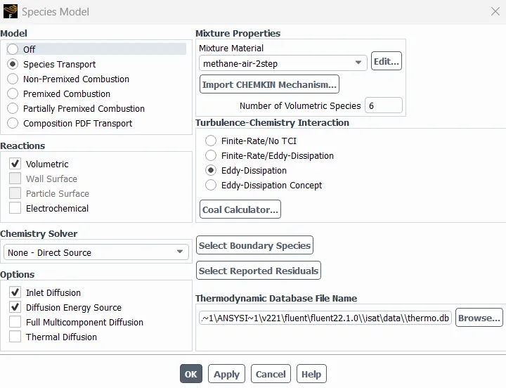
Species model was enabled. Species transport was selected, because it solves conservation equation for all species, which predicts the transport and their production in the combustion zone. In fluid phase volumetric reaction is considered always, so it was selected. Inlet diffusion and diffusion energy source was selected in this setup combustion chamber does not have any ignition source, combustion is arising due to diffusion turbulence of fuel and air. Methane-air-2step selected as mixture material which allows water addition. We proceeded with eddy dissipation model due to its robustness and it takes less time to solve model compare to other models.
Species model:
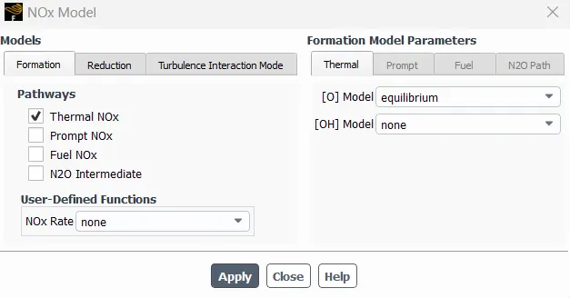
NOx model :
Soot model:
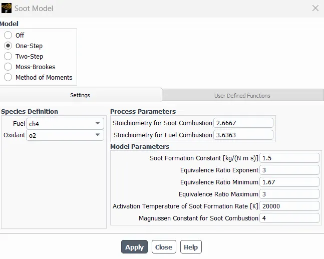
In this model the oxidant has to be changed to O2 otherwise the results will not converge.
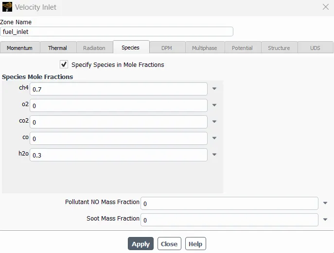
Air inlet velocity was 0.5m/s and fuel inlet velocity were given 80m/s in the boundary condition with 0.23 O2 and 1 CH4 by mass fraction. These derived from equation of natural gas combustion.
Total mole fraction OF air = 9.52 moles (2moles O2+2*3.76 moles N2)
Mole fraction of O2 = moles of O2/total moles = 2/9.52 = 0.21
Mass fraction of O2 in air = 0.23
Moles of CH4 = 1
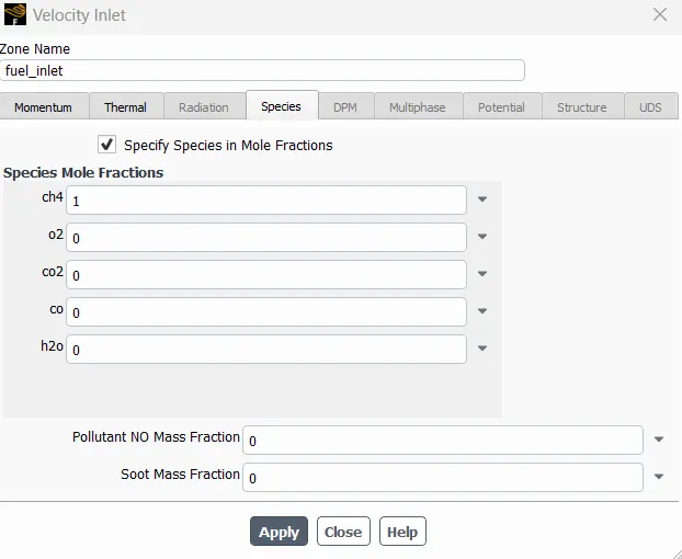
Mole fraction or mass fraction can be given to specify species. Nox model and soot model was also enable because we wanted to analyse Nox and soot formation.
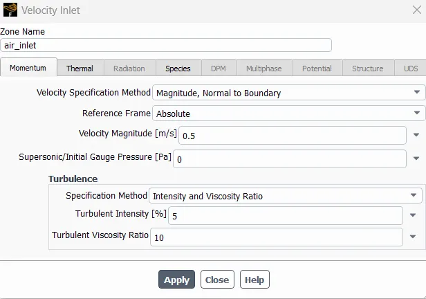
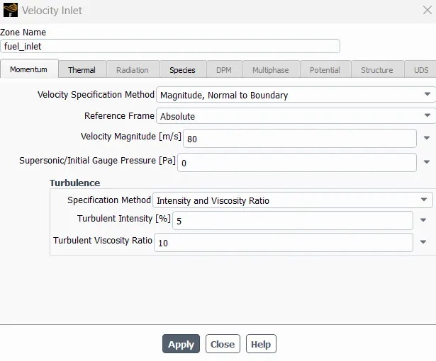
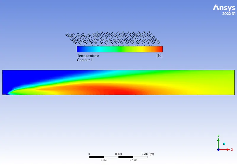
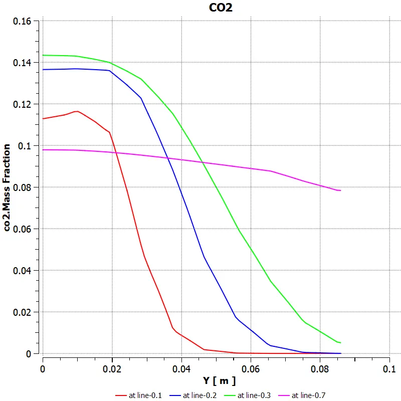
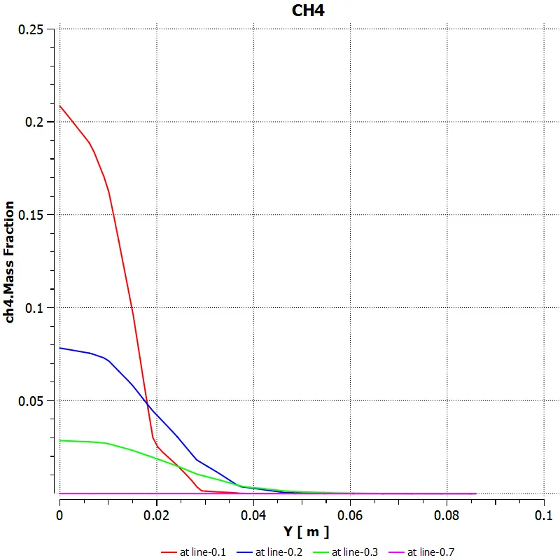
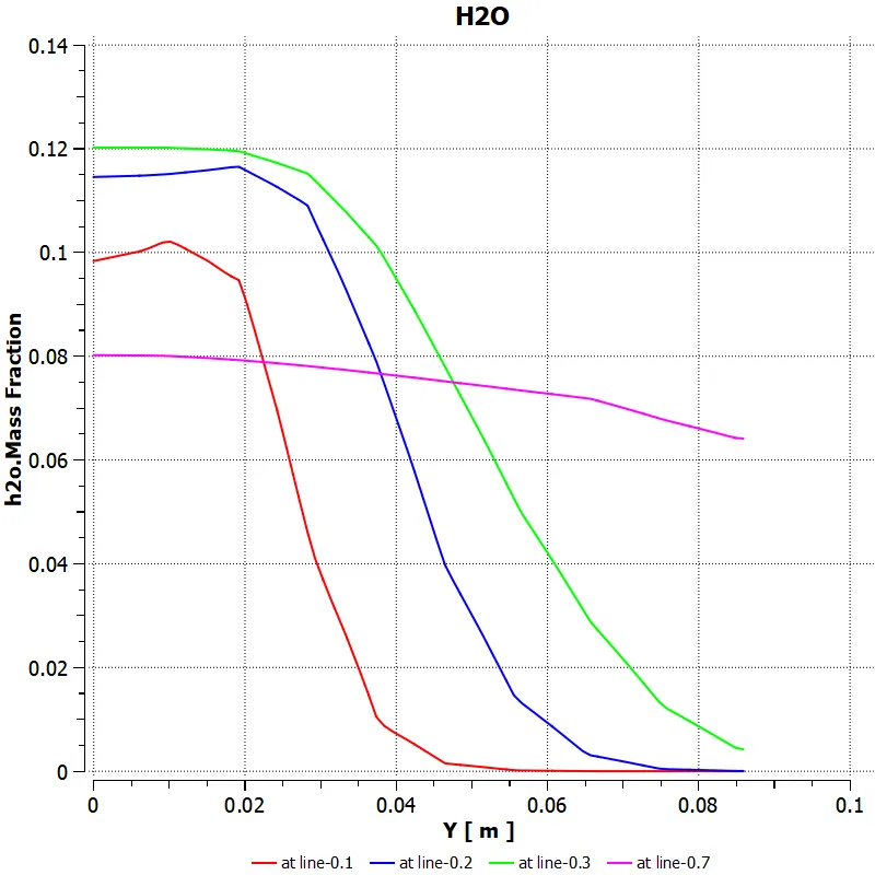
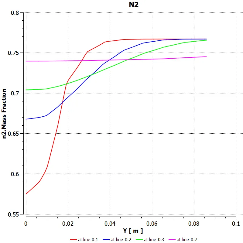
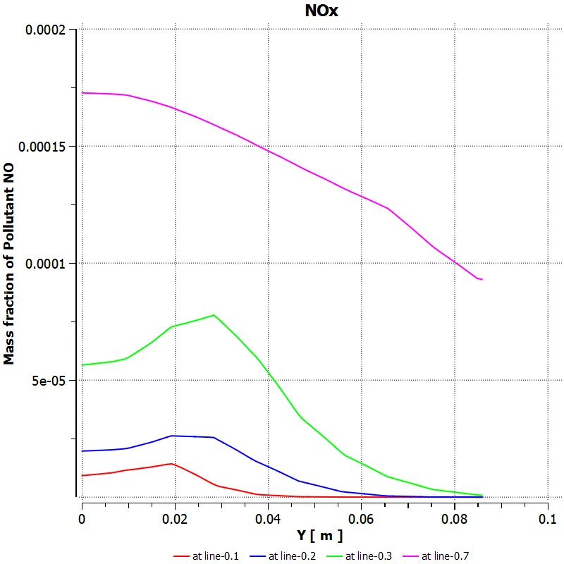
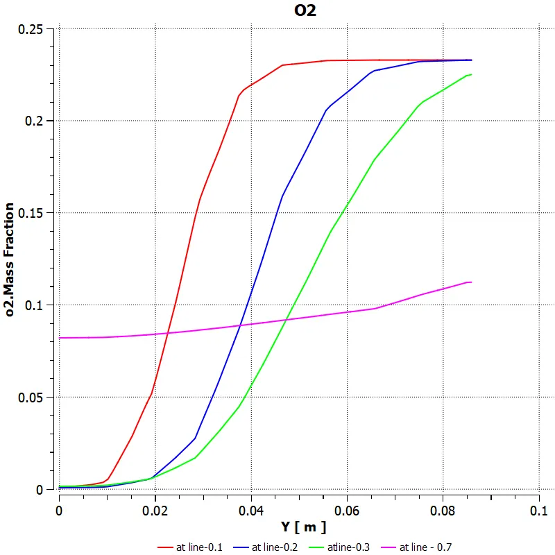
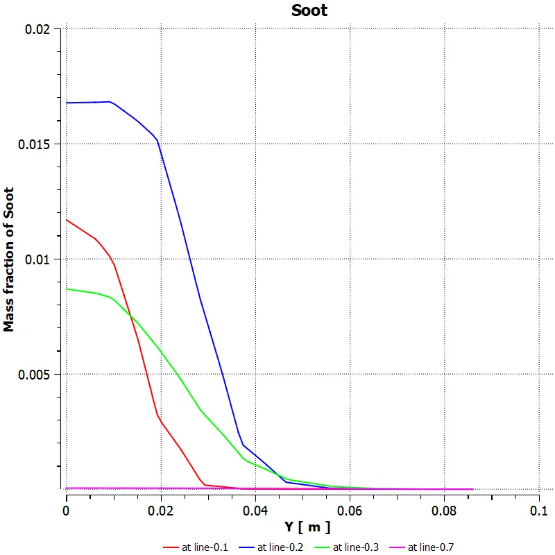
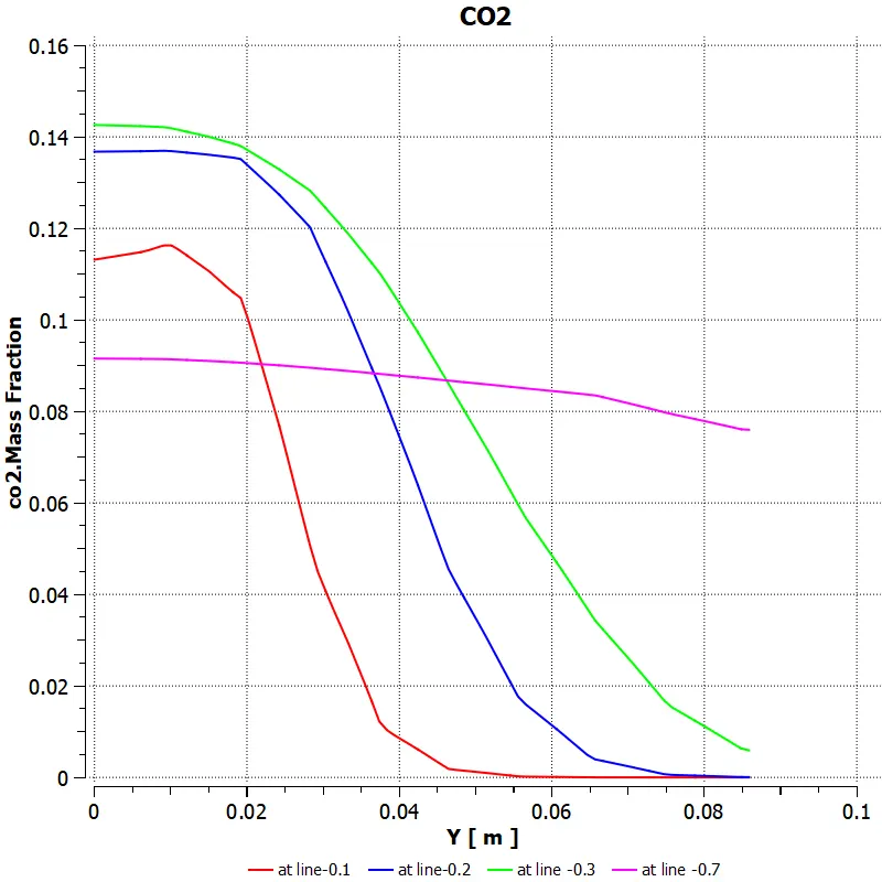
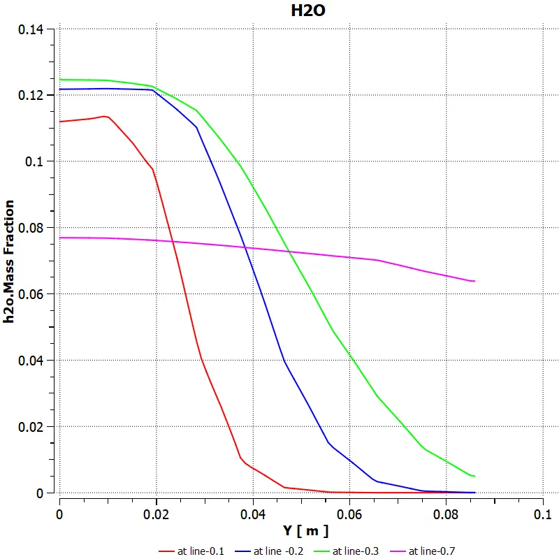
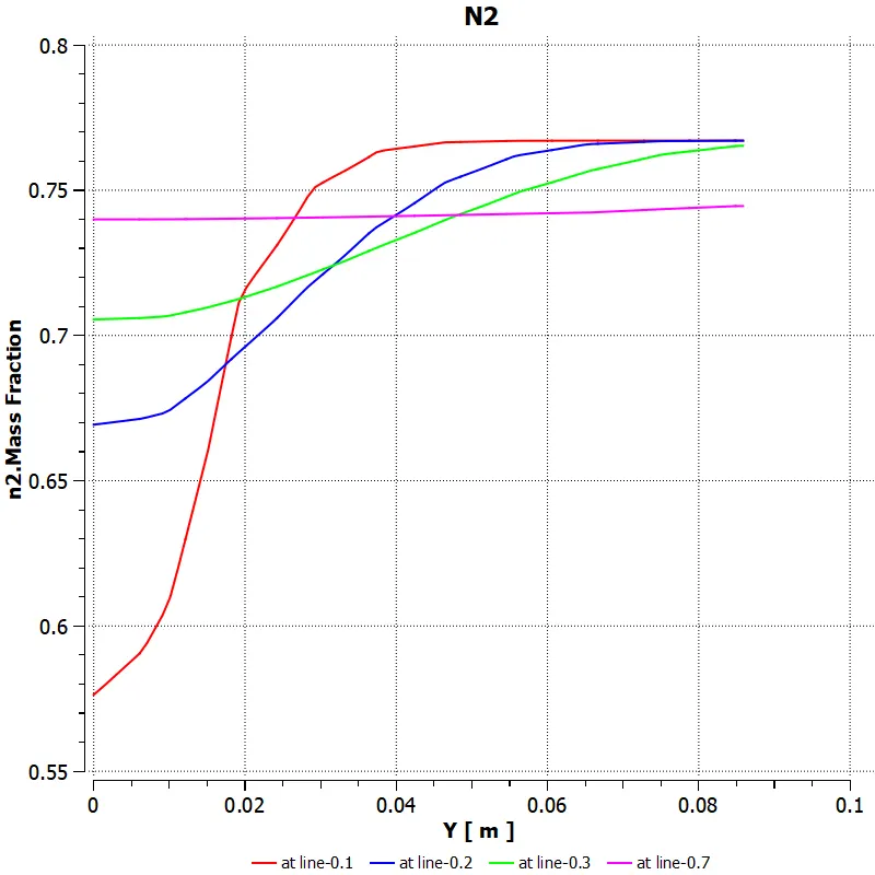
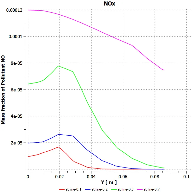
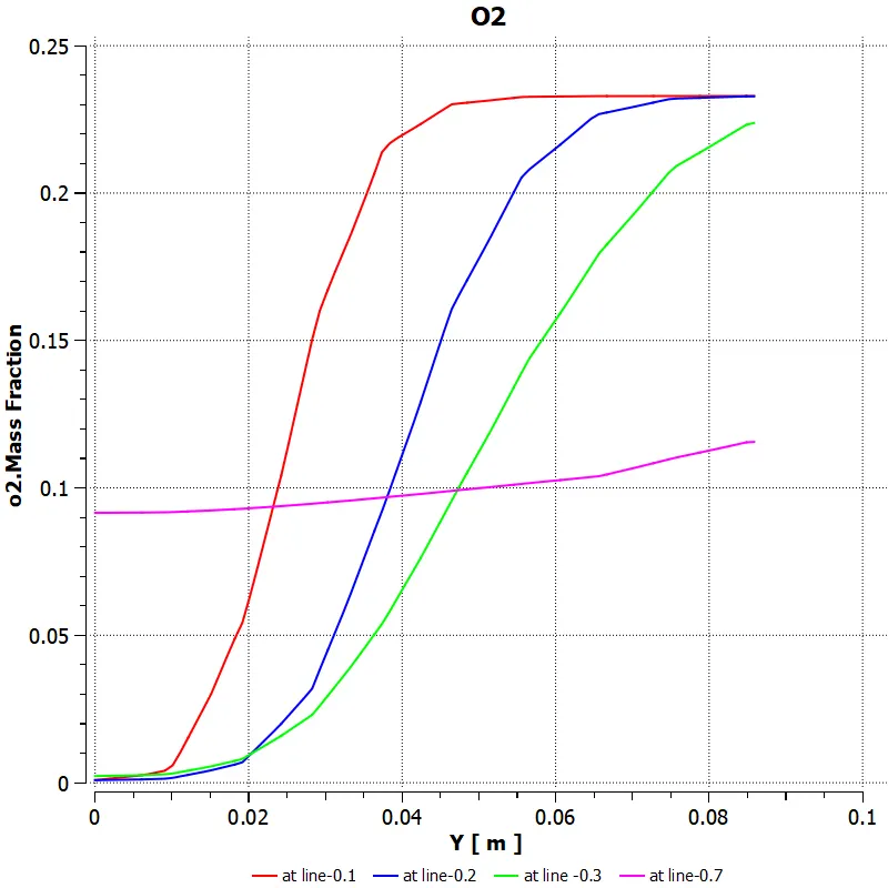
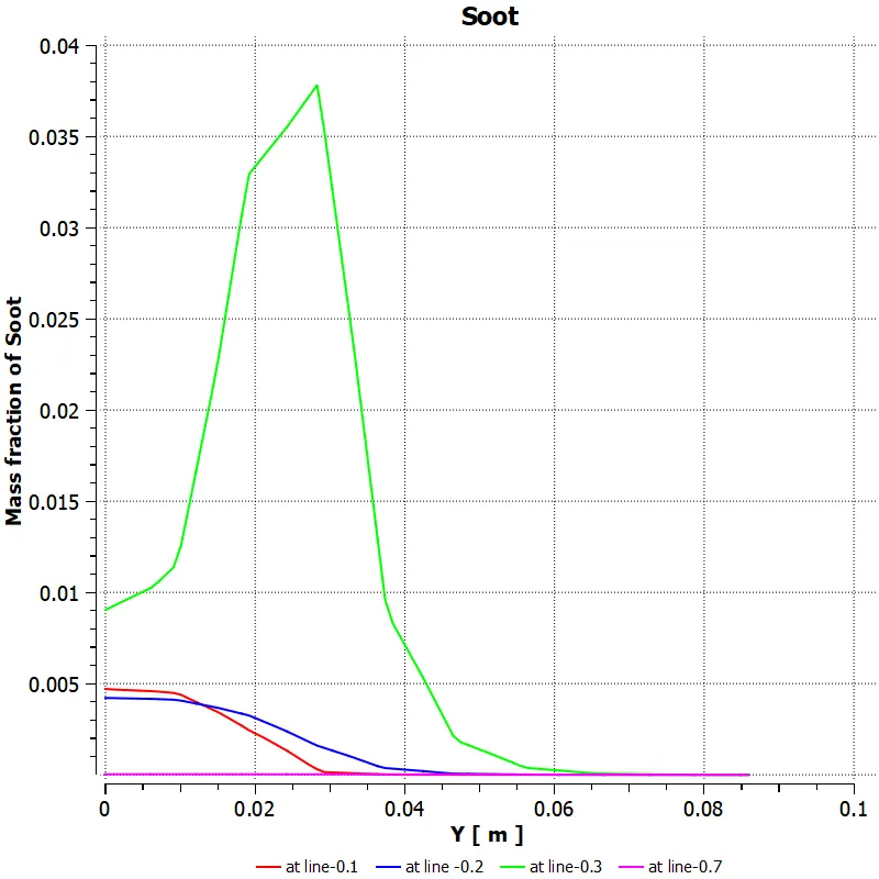
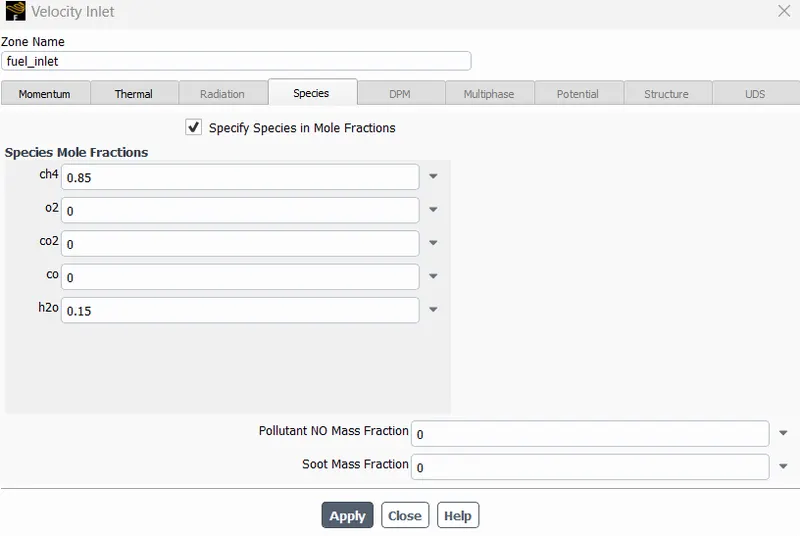
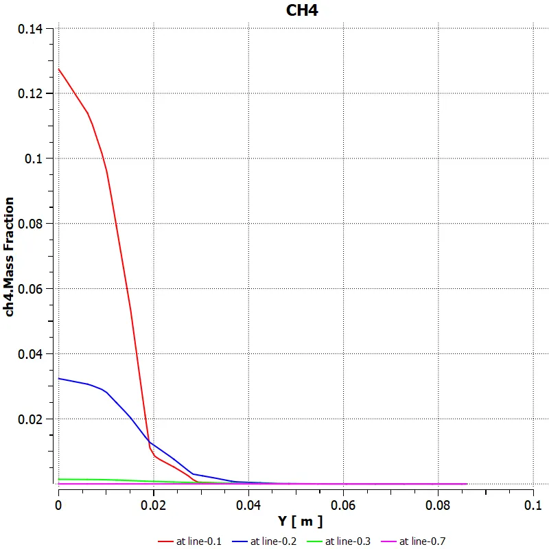
Temperature contour was created to get insights of flame front and temperature hotspots. Four probe lines were created at distance 0.1x, 0.2x, 0.3x, 0.7x x is the total distance, to inspect mass fraction of six species CO2, H2O, O2, N2, CH4 and NOx. Chart of soot formation was also plotted. In case 2 fuel is added into chamber with water from 5% to 30% to investigate the effect of water on soot formation.
METHANE MOLE FRACTION -1
In this case the mole fraction of the CH4 is taken as 1 and O2 as 0.21 which is a standard case. The temperature contour and the soot contours have given below along with the mass fraction charts of all the gases that mentioned above at different location to observe its propagation.
Temperature Contour :
In here without any water at the inlet the maximum temperature attained inside the combustion chamber is 2250K
CO2 mass fraction :
Methane mass fraction:
Water mass fraction:
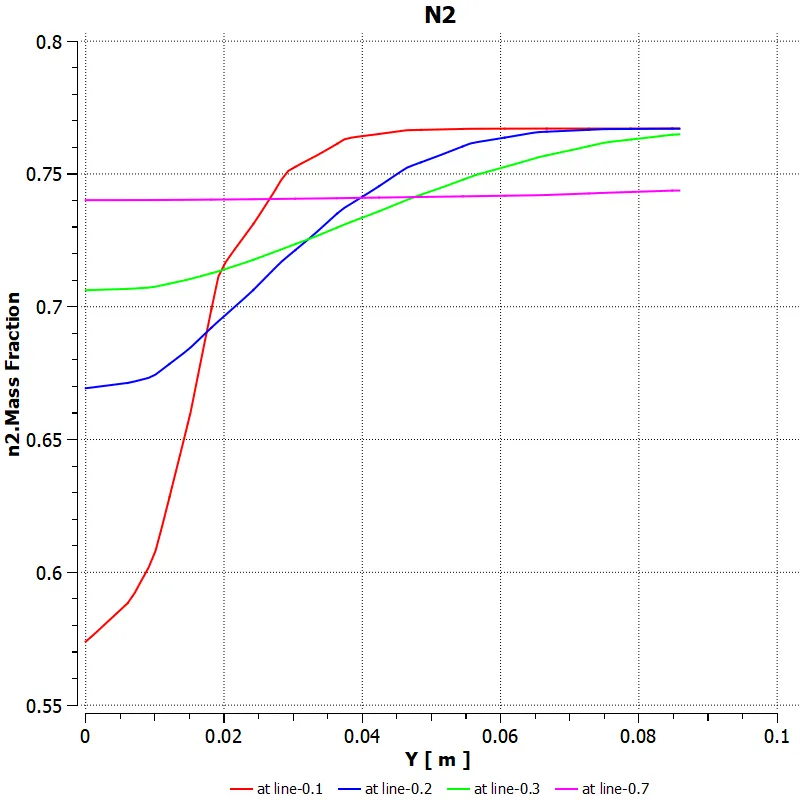
Nitrogen mass fraction:
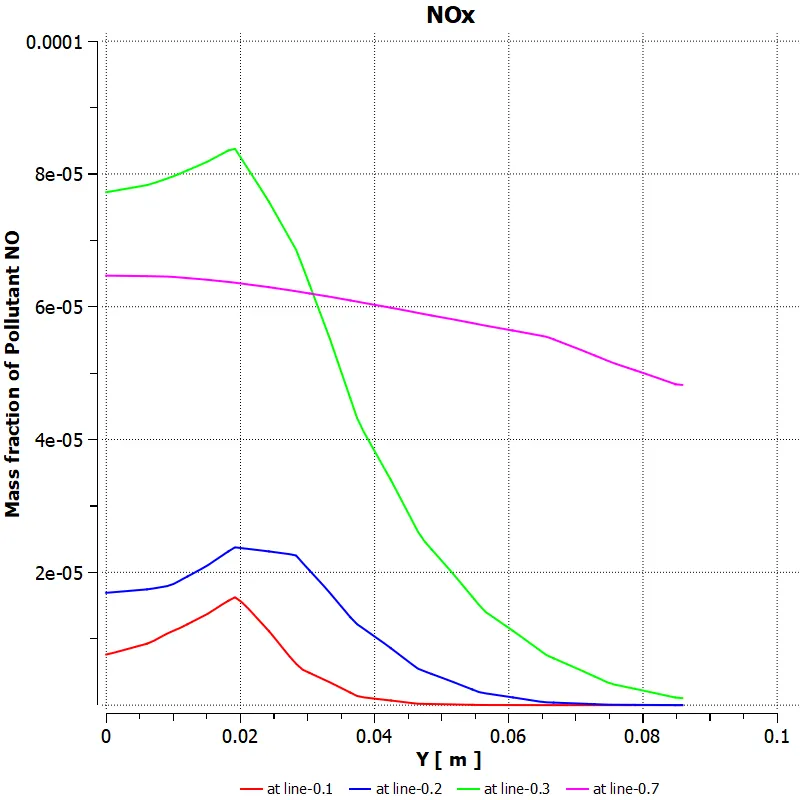
NOx mass fraction:
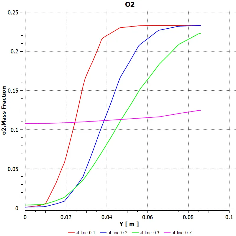
Oxygen mass fraction:
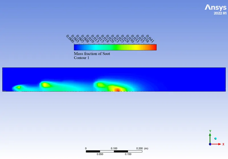
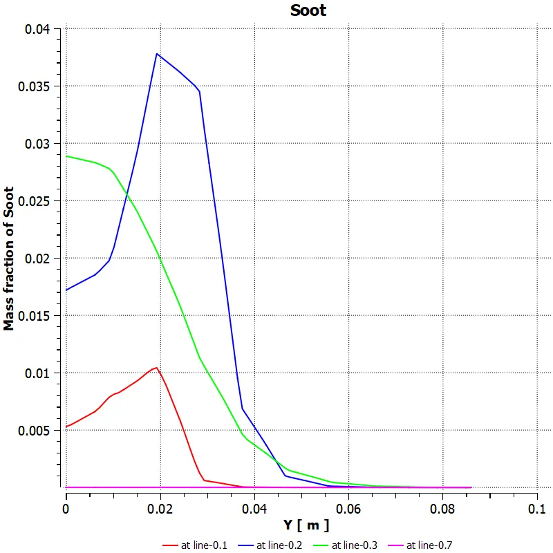
Soot mass fraction:
Soot contour:
METHANE MOLE FRACTION -0.95
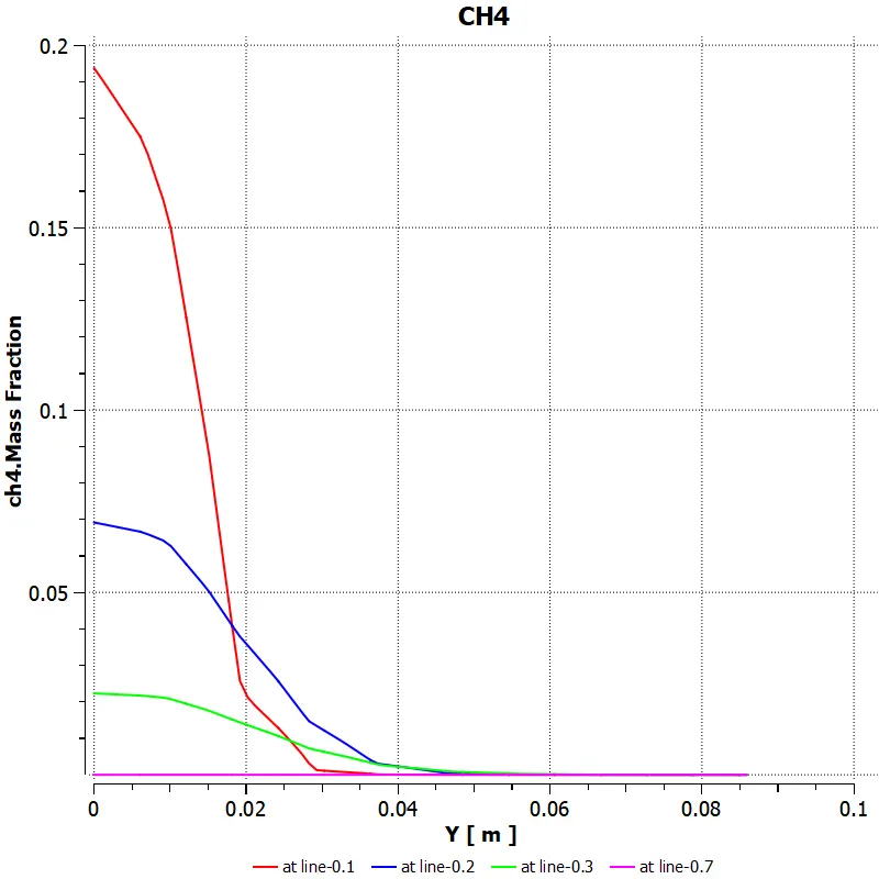
In the second case the 5% water has been added which reduces the mole fraction of the methane to 0.95 and adds 0.05 to water to obeserve the chnages in the mass fraction of the gases.
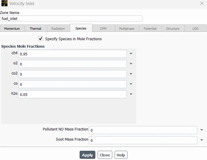
Temperature contour:
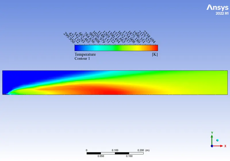
methane mass fraction:
carbon dioxide mass fraction:
water mass fraction:
nitrogen mass fraction:
NOx mass fraction:
Oxygen mass fracion:
Soot mass fraction:
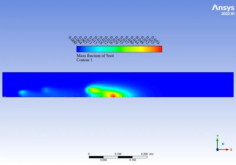
Soot contour:
METHANE MOLE FRACTON -0.85
Temperature contour:
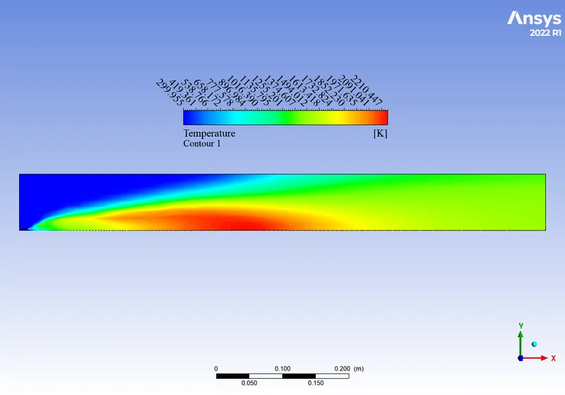
methane mass fracion:
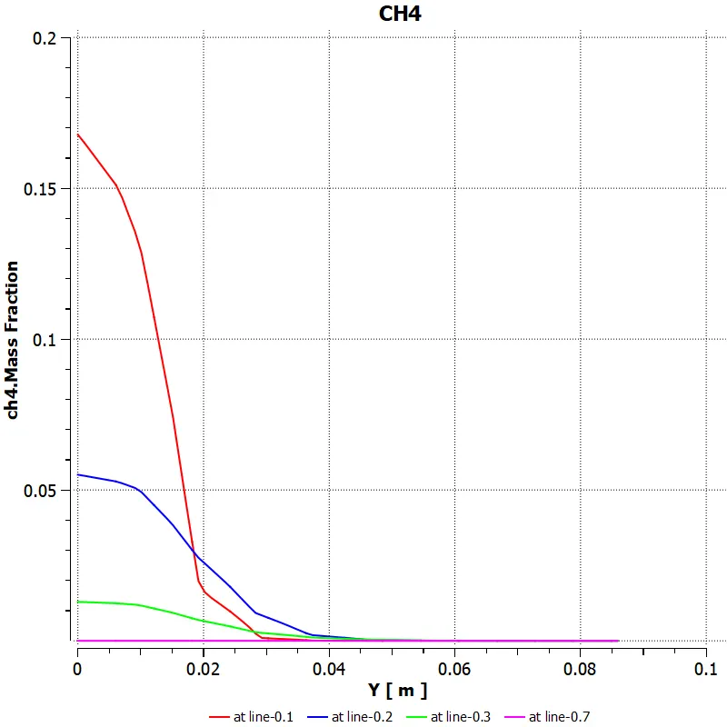
carbon dioxide mass fraction:
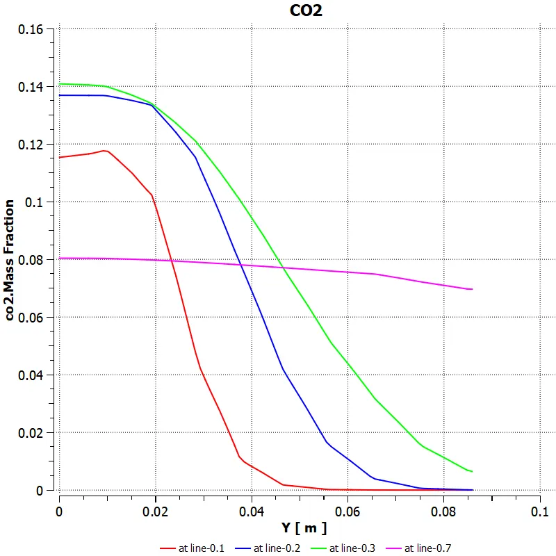
water mass fraction :
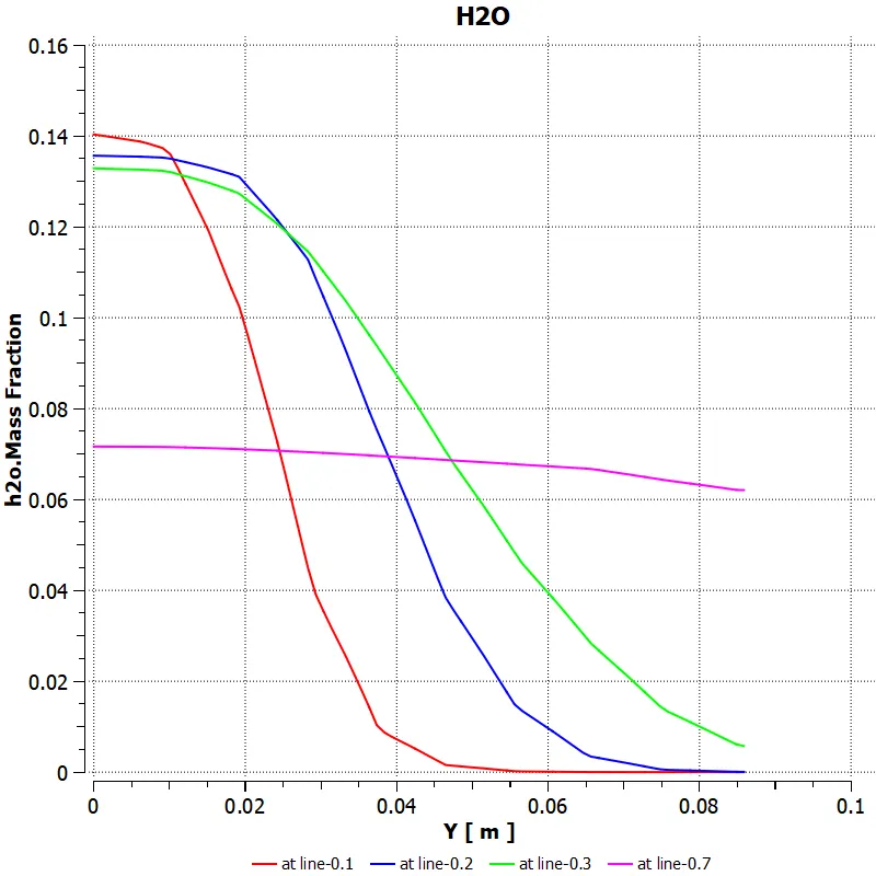
Nitrogen mass fraction:
NOx mass fraction:
oxygen mass fraction:
Soot mass fraction:
Soot contour:
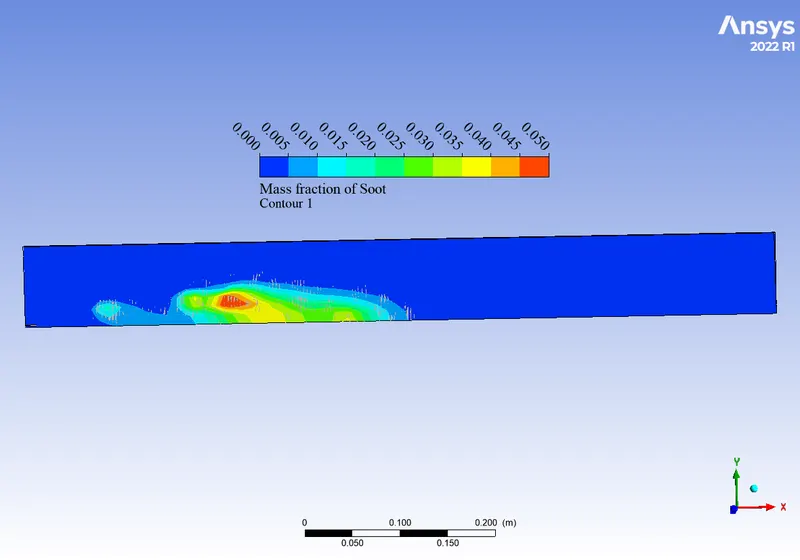
METHANE MOLE FRACTION- 0.7
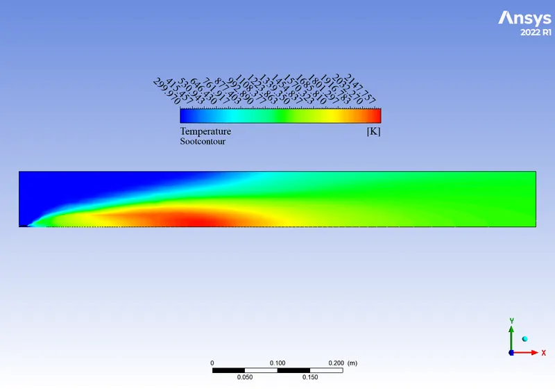
Temperature contour:
methane mass fraction:
carbon dioxide mass fraction:
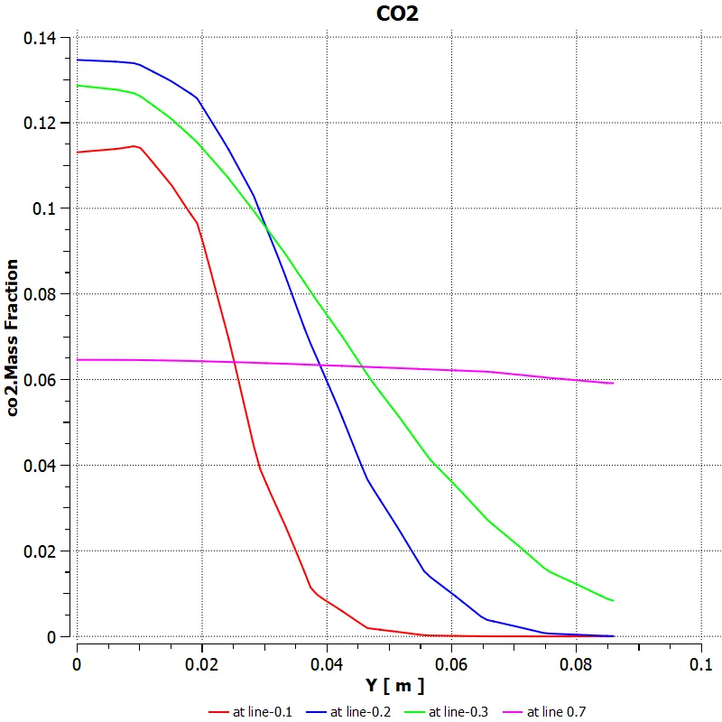
water mass fraction:
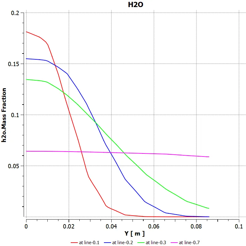
nittrogen mass fraction:
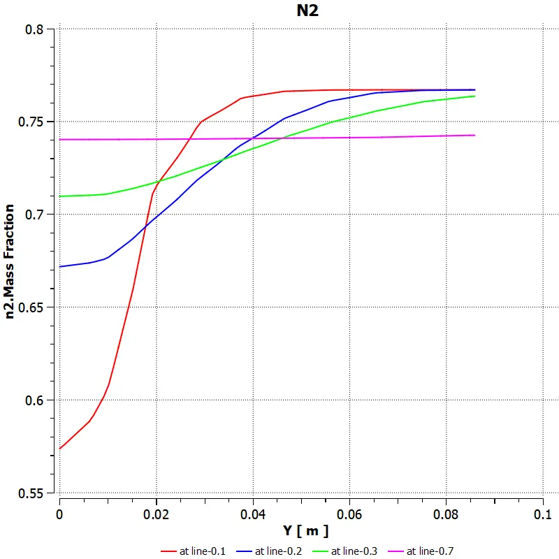
NOx mass fraction:
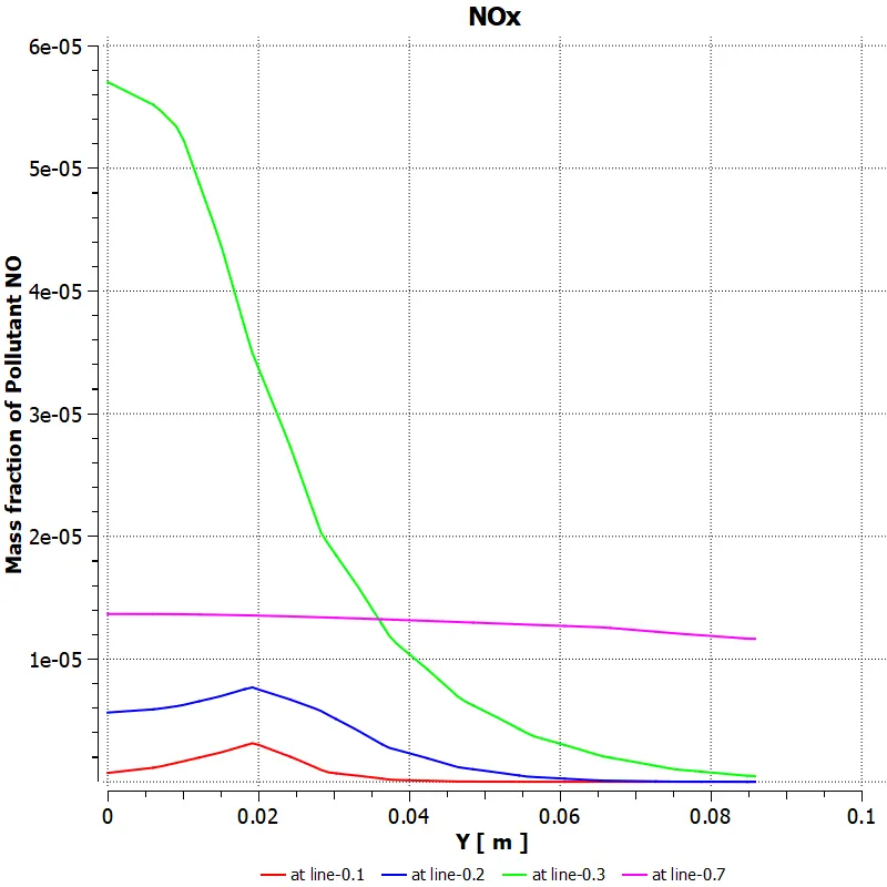
oxygen mass fraction:
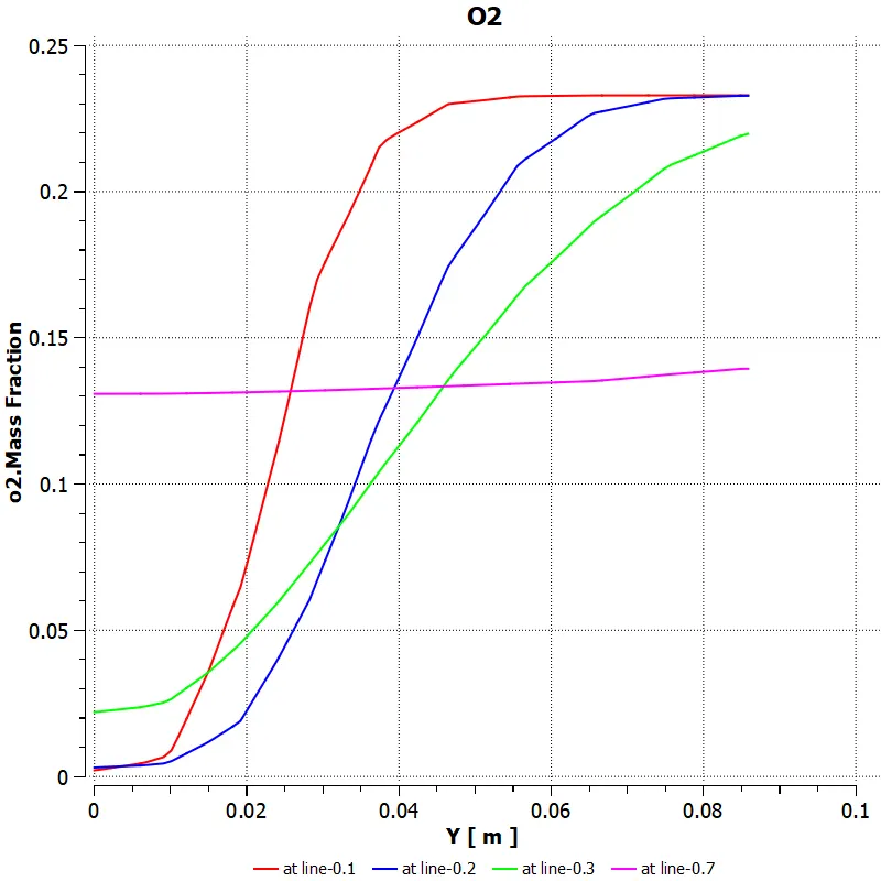
Soot mass fraction:

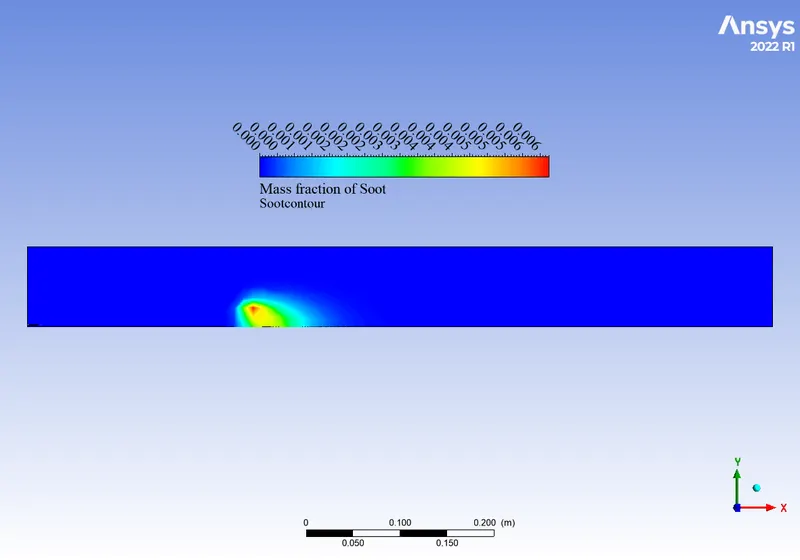
Soot contour:
CONCLUSIONS
From the results we can observe that the with increase in the water at inlet the maximum temperature of the combustion in reduced and so as the soot and Nox mass fraction.
- Adding water from 5% to 30% decreases the emission of Nox and Soot pollutants.
- Adding water also decreases the highest temperature.
- Highest temperature is achieved in the proximity of the Inlet.
- Low combustion temperature provides a number of advanced combustion strategies, including homogeneous charge compression ignition (HCCI) or premixed charge compression ignition (PCCI). LTC combustion can produce very low emissions of NOx and PM but often results in increased CO and HC.