Week 10 - Simulating Combustion of Natural Gas.
Objective:-
- To perform a combustion simulation on the combustor model and plot the variation of the mass fraction of the different species CO2, H2O, CH4, N2, O2, NOx emissions & Soot formation.
- To perform above combustion simulation with varying water containe in fuel from 5 to 30%.
Theory:-
Chemical Kinematics:- It is branch of physical chemistry that is concerned with understanding the rates of chemical reactions. It includes, How experimental condations influnce the speed of chemcial reaction and yield information about the reaction mechanisam.
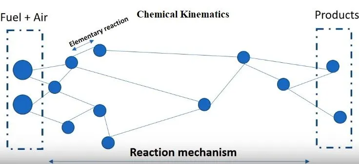
Reaction Mechanisam:- Reaction mechanisam is the step by step sequence of of elementary reactionby which overall reaction occures. In general a recation have 2 thing
1) Reactant
2) Products
3) Catalyst (Not in all reactions)
But during the reaction there are some intimidatory activites like some compound or molecule or free radical or ions are reacting with each other , these reaction occures because these things are not stable because of high potetial energy so finaly after may these type of activity we get the products. These activity during the reaction is called as Elementary reactions and these unstable component called as intimidatory species.
This complete process from reactant to product through these intimidatory species is Knowns as Reaction pathway.
Imporatnce of Reaction Pathway
- It helps us to pridict ignition delay by knowing the reaction time for that elementary reaction which start the combustion.
- With help of this we can find the heat release rate in that reaction which start combustion and then findout the rate of wotk done after the cobustion start.
- It help in emission control by giving data of soot and NOX formation in reaction.
Soot is a mass of impure carbon particles resulting from the incomplete combustion of hydrocarbons. It is a black substance formed by combustion or separated from fuel during combustion, rising in fine particles, and adhering to the sides of the chimney or pipe conveying the smoke.
Combustion Based on mixing
- Non-premixed combustion:- Direct injection in CI engines.
- Premixed combustion:- Charge mixed in carburator and ater combustion in SI engines.
- Partially premixed combustion:- Eartly combustion in IC engines.
Combustion Based on phase
- Fluid phase (Volumetric phase)
- Wall (surface recation)
- Particales (surface recation)
- Porous region(after treatment system)
Some CFD model for combustion simulation
Eddy dissipation model - The eddy dissipation model is based on the concept that chemical reaction is fast relative to the transport processes in the flow. When reactants mix at the molecular level, they instantaneously form products. The model assumes that the reaction rate may be related directly to the time required to mix reactants at the molecular level.
The eddy dissipation model was developed for use in a wide range of turbulent reacting flows covering premixed and diffusion flames. Because of its simplicity and robust performance in predicting turbulent reacting flows, this model has been widely applied in the prediction of industrial flames.
The finite chemistry model –
The finite-rate chemistry model allows the computation of reaction rates described by the molecular interaction between the components in the fluid. It can be combined with the eddy dissipation model for flames where chemical reaction rates might be slow compared with the reactant mixing rates. The finite-rate chemistry model is best applied to situations where the chemical time scale is rate-limiting. This model can be used in conjunction with both laminar and turbulent flow.
The flamelet model –
The flamelet model can provide information on minor species and radicals, such as CO and OH, and accounts for turbulent fluctuations in temperature and local extinction at high scalar dissipation rates, for the cost of solving only two transport equations. The model is only applicable for two-feed systems and requires a chemistry library as input. The model can be used only for non-premixed systems.
Simulation Process
1) Pre processing:-
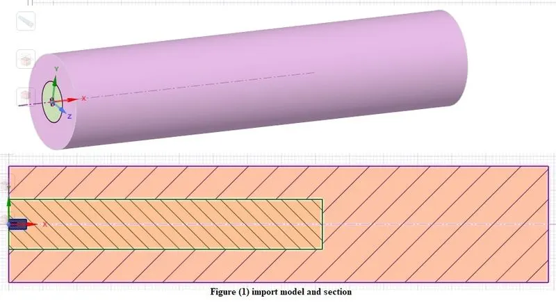
a) Geometry modeling:- First import the geometry in space claim, Now this is a 3D axis symetry model we convert this to a 2D model for simple and fast simulation. For this first make a section about front pane on this body as shown in figure then use split body command to split body through horizontal plane now copy this 2D geometry and pase in new space claim file.
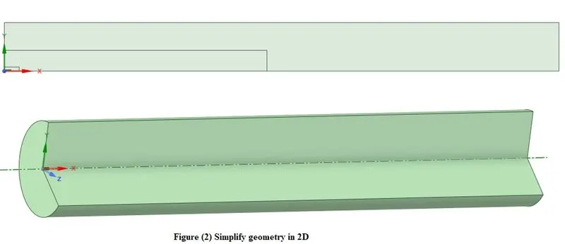
Now if you revolve it about x axis you get back the 3D model but we don't do this now because we need 2D geometry so pre escap and active the share topology and close space claim.
b) Meshing:- Now in meshing here inlet of fule is very small so we active capture defeaturing,curvature and proximate with size 0.05mm. and quart mesh of size 5mm in entaire domain.
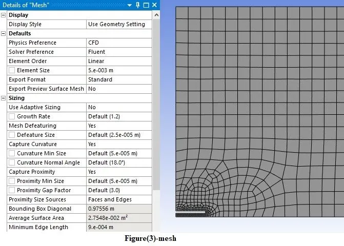
Mesh qualtiy check, Number of elements 3558
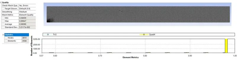
c) Name selection:-Now name of boundaries as shown in figure
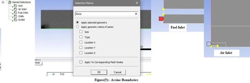
Makes boundary selection as Air inlet ,Fuel inlet, outlet, wall and axis then close and open fluent.

2) Simulation setup
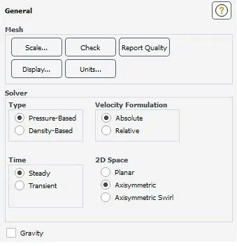
a) General :- Now this is a axis symetry model so make sure in general setting you selected axis symmetry. Here is simulation is pressure base steady staste simulation.
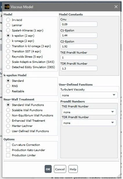
b) Viscous model:- Now in model selection first we select standerd k-epssilon model
c) species model:- Now on physics go to species , select the species transort and
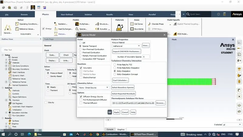
Now select material mathene-air , Reaction type volumetric and in turbulent chemesty active eddy dissipation
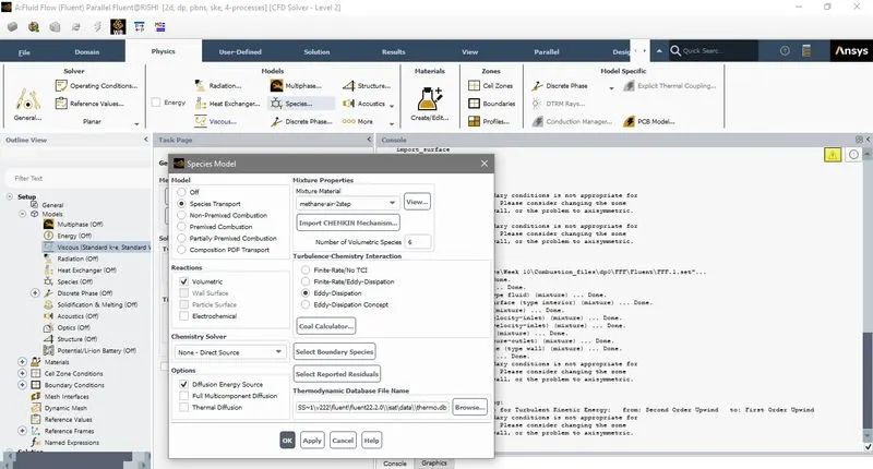
Now for our case 2 where we simulate with water containe we have to use material matene-air step2
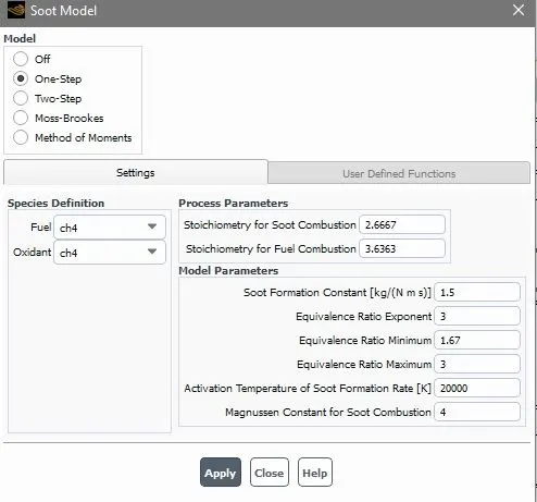
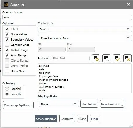
Soot model
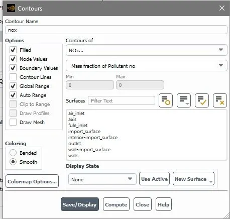
NOx model
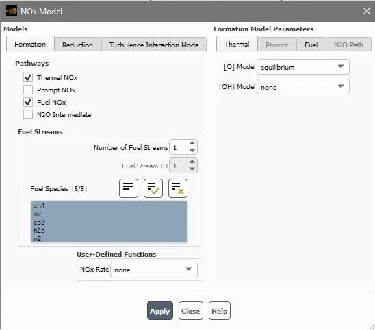
d) Boundary condations
Inlet Boundary conditions -
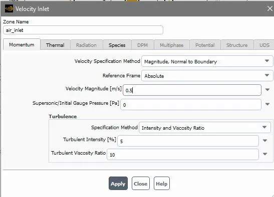
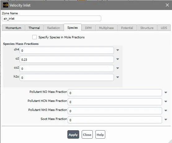
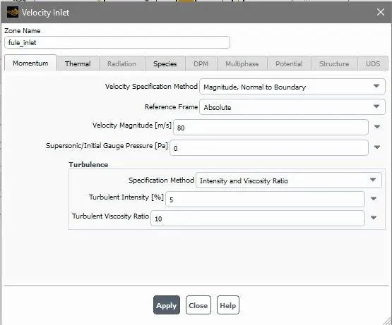
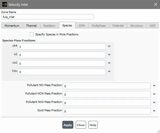
Air inlet velocity was 0.5m/s and fuel inlet velocity were given 80m/s in the boundary condition with 0.23 O2 and 1 CH4 by mass fraction. These derived from equation of natural gas combustion.
Total mole fraction OF air = 9.52 moles (2moles O2+2*3.76 moles N2)
Mole fraction of O2 = moles of O2/total moles = 2/9.52 = 0.21
Mass fraction of O2 in air = 0.23
Moles of CH4 = 1
Mole fraction or mass fraction can be given to specify species. Nox model and soot model was also enable because we wanted to analyse Nox and soot formation.
Air inlet BC
Fuel inlet BC
Contours capture
Simulation run
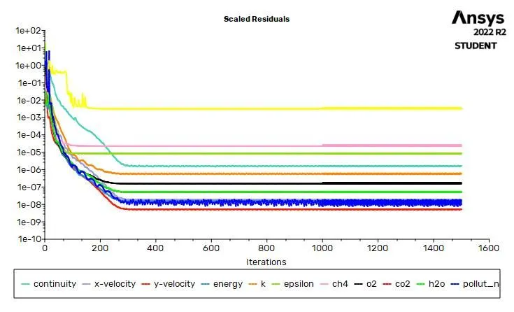
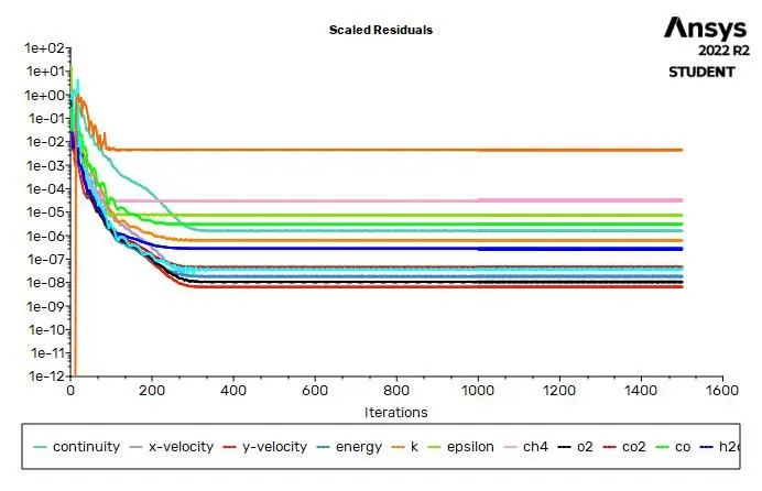
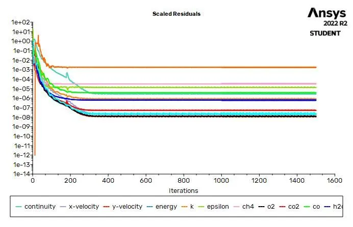
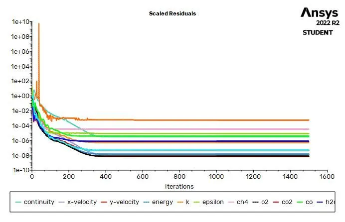
run simulation for 1500 iterations
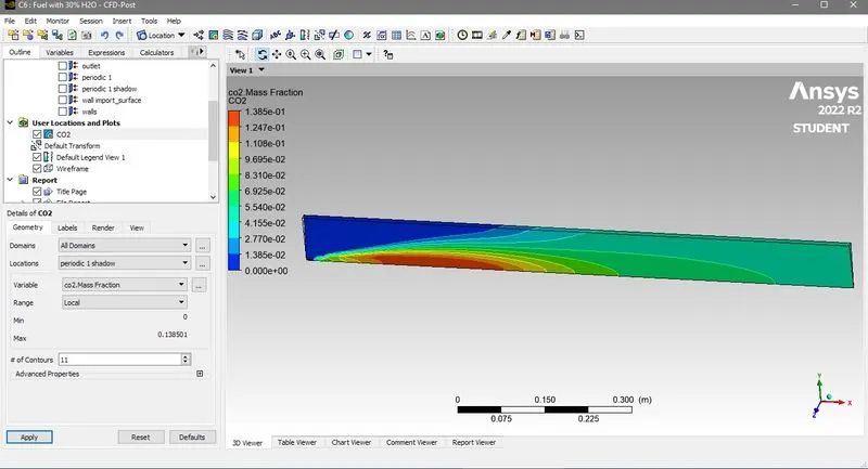
3) Post procedure:- After simulation run close the fluent and one CFD post and makes countoure of CO2,CH4,O2,N2,H2O,NOx and soot
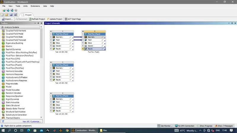
Now make study for case I and II in work bench
Results
CaseI
Residual plot
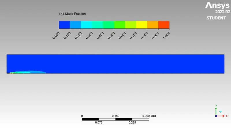
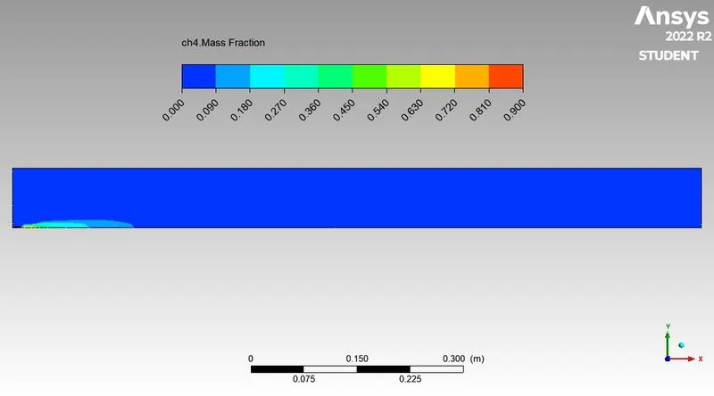
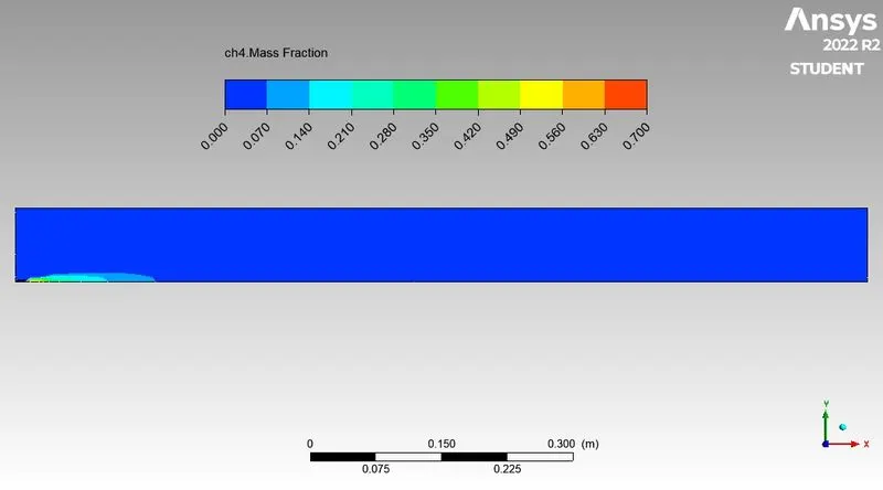
CH4 mass fraction
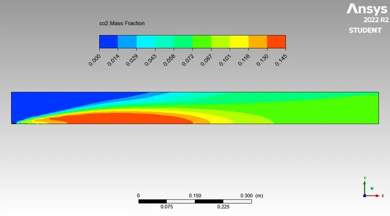
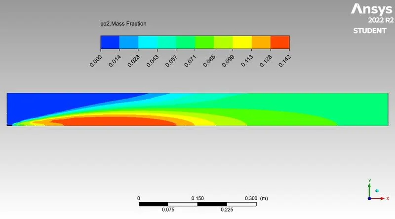
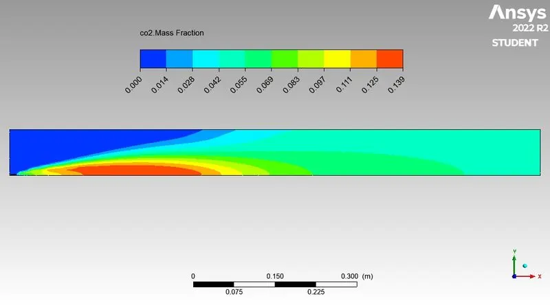
CO2 mass fraction
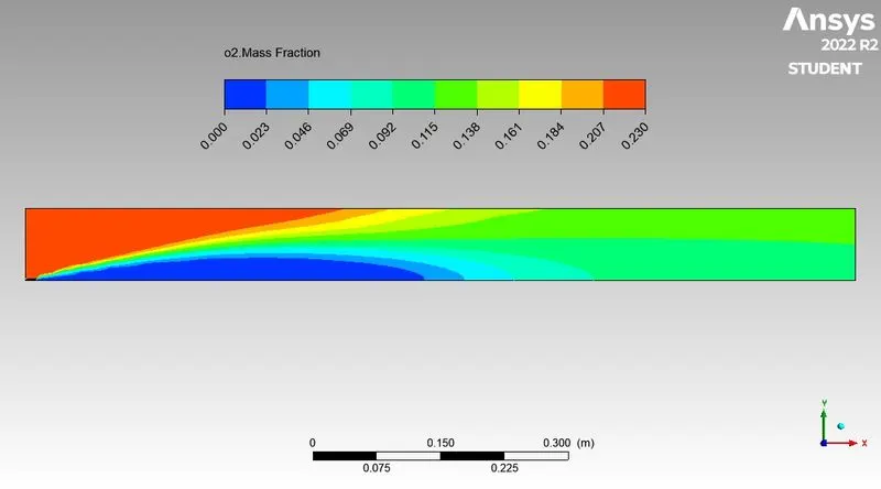
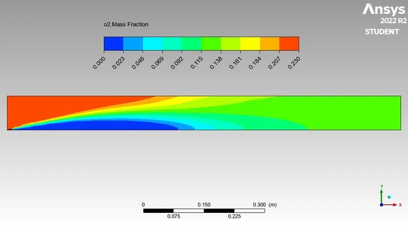
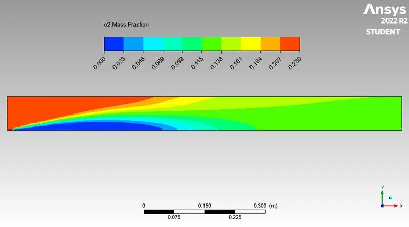
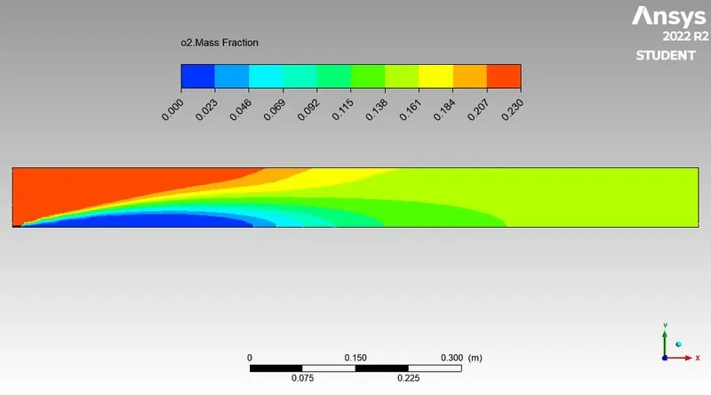
O2 mass fraction
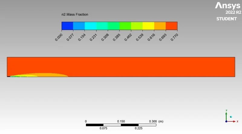
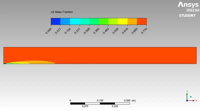
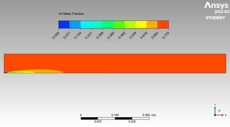
N2 mass fraction
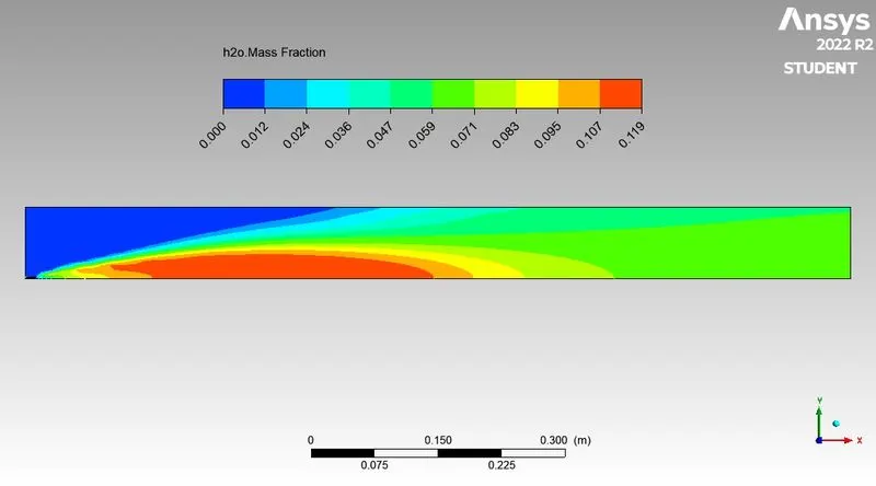
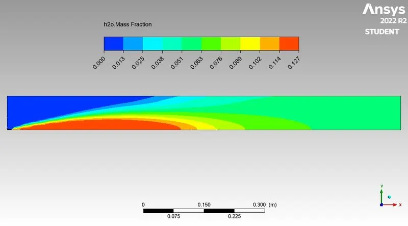
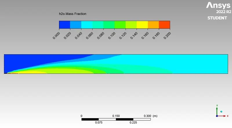
H2o mass fraction
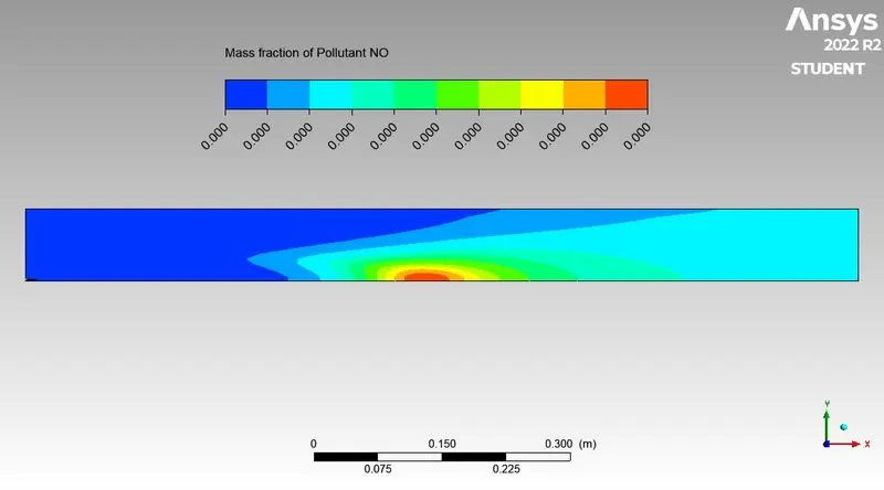
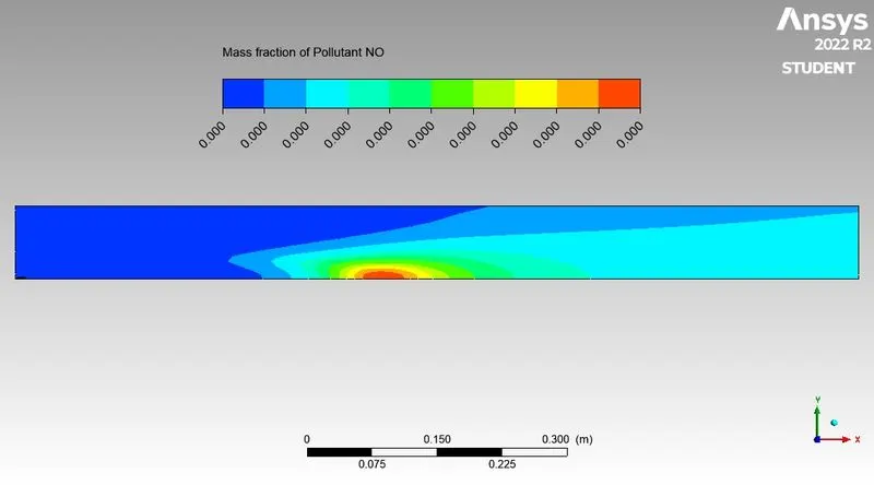
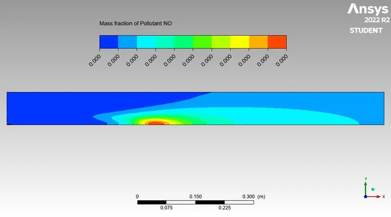
NOx
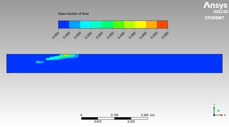
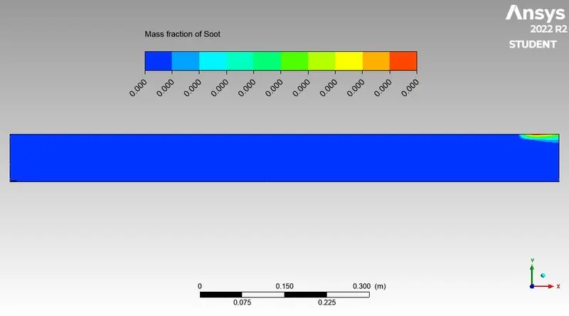
Soot
Case II
part1 water contain 10 %
Residual
Mass fraction of CH4
Mass fraction of CO2
Mass fraction of N2
Mass fraction of O2
Mass fraction of H2O
NOx
Soot
Part 2 water contain 20%
Residual
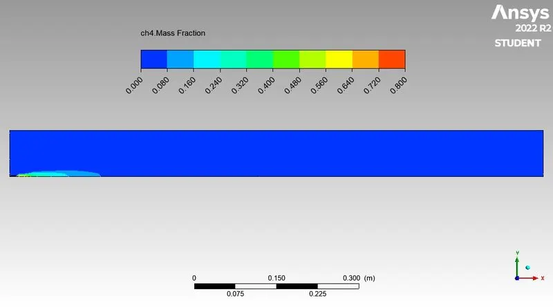
Mass fraction of CH4
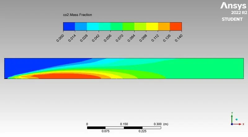
Mass fraction of CO2
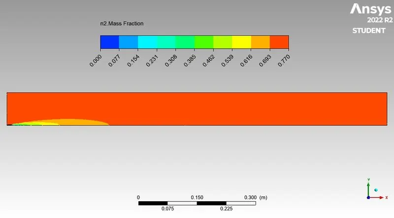
Mass fraction of N2
Mass fraction of O2
Mass fraction of H2O
NOx
Soot
Part 3 Water contain 30%
Mass fraction of CH4
Mass fraction of CO2
Mass fraction of O2
Mass fraction of N2
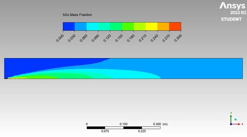
Mass fraction of H2O
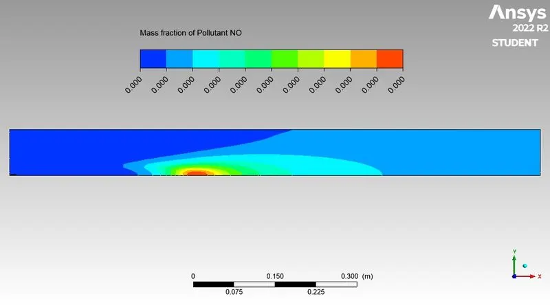
NOx
Soot
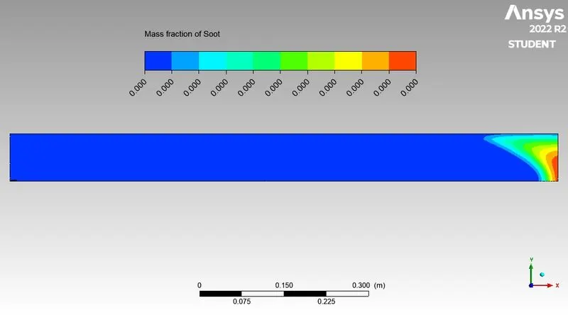
Conclusion:-This study comparing the mass fraction of product produced during combustion of natural gas and soot formation with or without water contain here CO2,N2 and O2 mass fraction are almost same in all case but change in NOx,H2o and Soot.
Soot is increase with water contain percentage and mass containe come to middle of combuston chamber as we increase water contain.water inlet is affecting soot formation but we can’t say much about it and NOx mass fraction is decreasing as water content is increasing. Methane is decreasing as we are proceeding towards outlet, because burning is arising somewhere middle of the combustor.
Soot and Nox has adverse effect on environment although soot can be used as black pigment. Soot can be reduced by after treatment methods. In this study we added water into fuel and simulated.