Week 3 Challenge : CFD meshing on Turbocharger
Aim:- To perforam CFD Meshing of Turbocharger in ANSA with different targent for differnt bodies.
Obejctive:-
I) Geometry check and clean up using various TOPO Geometry clean up tools.
II) Assign PID to different component of turbocharger.
III) Perform surface mesh with the given target lengths as per PIDs.
- Blade stage-1 = 1 mm
- Blade stage-2 = 1 mm
- Impeller = 2 mm
- Shaft rotor = 1 mm
- Turbo casing = 5 mm
- Compressor casing = 5 mm
- Inlet casing cover = 5 mm
Procedure:-
I) Geometry clean up
Step1:- First Import Turbocharger model then go to Checks Maneger> Select Geometry > click To check > Click Exicute
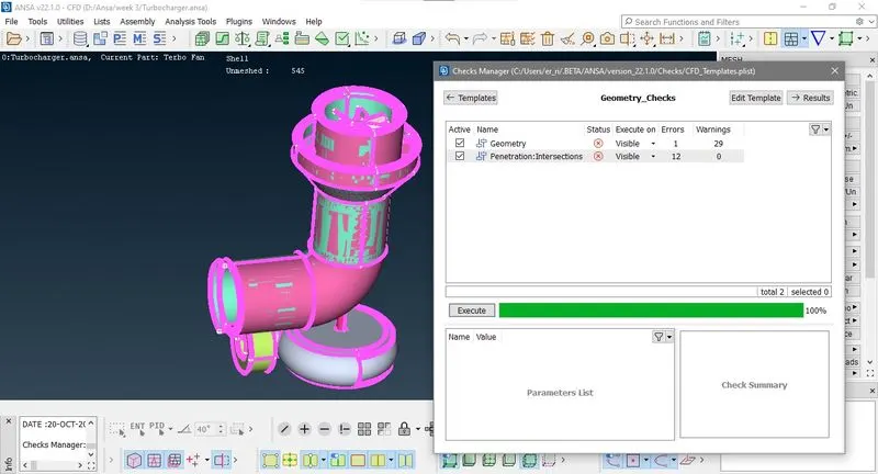
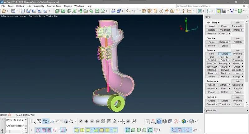
Step 2:- Now here 12 intersection are there, then we delete unnecessarily PID as shown in below image.
TOPO > FACES > Delete > PID mode >select PID >press scrole >OK
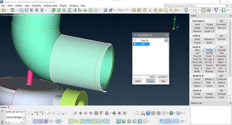
Step 3:- Now show all and delete cylindrical surface as shown in below image
TOPO > FACES > Delete > ENT mode >select surface >press scrole>Delete
Now go to TOPO> FACES>New>Coons> Loop select> select single cons of missing surface as shown in below image
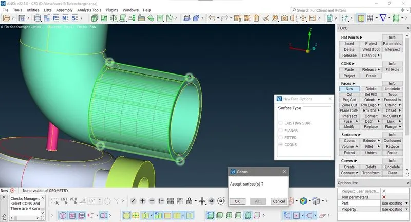
Step 4:- Rotage model and you see a missing surface now go to TOPO >Hot Points >Insert
Step 5:- In the below image you can see cylinder surface have some intercut. Here single cons at below face are not same as upper face and you can't make smooth surface with these cons. So we can either creates new curve or project hot point on upper con.
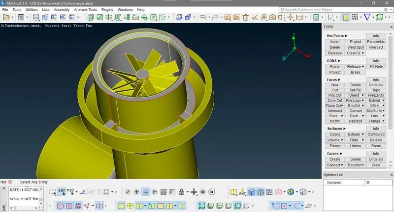
Now go to the TOPO>Curves>Transform
select single cons >press scrole> select points as show in image ,Then press scrole and click ok.And repect this with next single con.
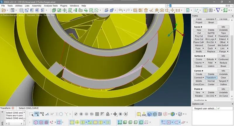
TOPO>Surface>coons> select cons and created curve
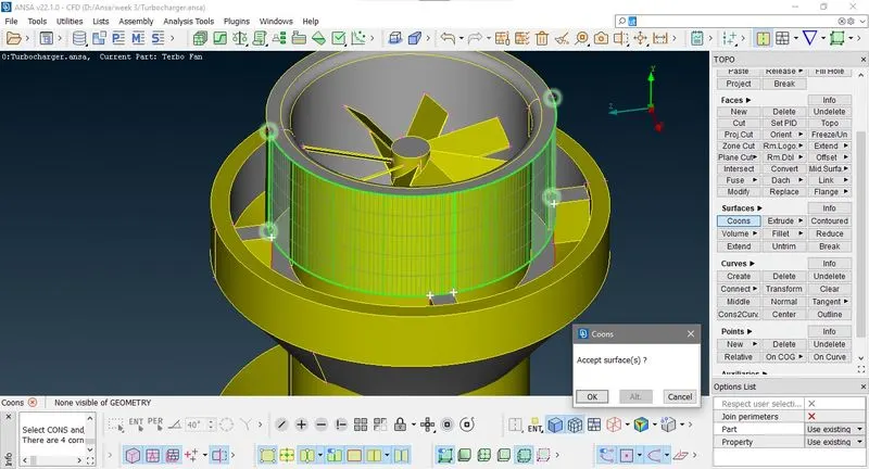
TOPO > Faces> New >coons Loop mode select coons and press scrole.
Repete for next surface.
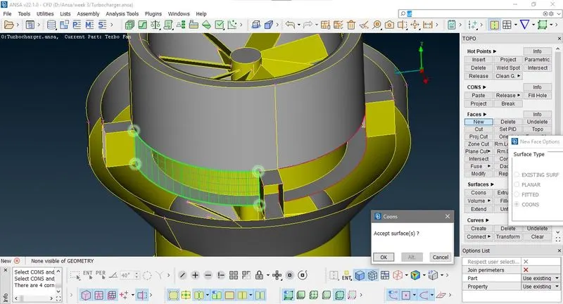
TOPO>Curves >Delete and select curves which you created.
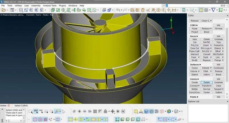
Step 6:-Now here in Turbo casing conical surface is intersecting with cylinder surface.
Go to TOPO> Faces>Intersect> select cone surface as first surface > press scrole > select cylinder surface as second surface > Press scrole
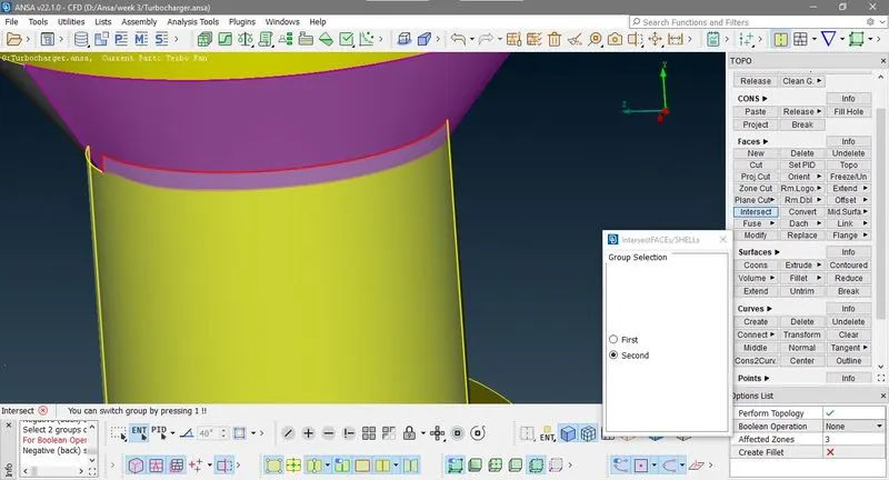
Here the resulted surface have under cut but we ignore it because it is outer surface and our flow internal.
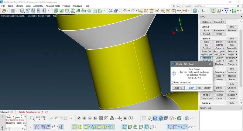
Step 7:- Now look at compressor casing its half outer face is also missing but this surface can not directly made by coons because of surface curvature ,we use mirror option and mirror other half surface. For mirror we required any line or plane but here we use 3 point option which means mirror plane passing through these points.
For this first create a point go to TOPO>Hot Points>Insert > Click mid of single con
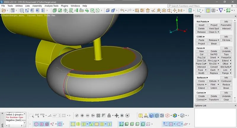
Go to Utilities > Transdorm > Entites > select surface to be mirror i.e. outer surface of compressor casing > press Scrole> Symmetry> select Mirror 3 points plane > select points as shoen in below image >Press scrole> Ok
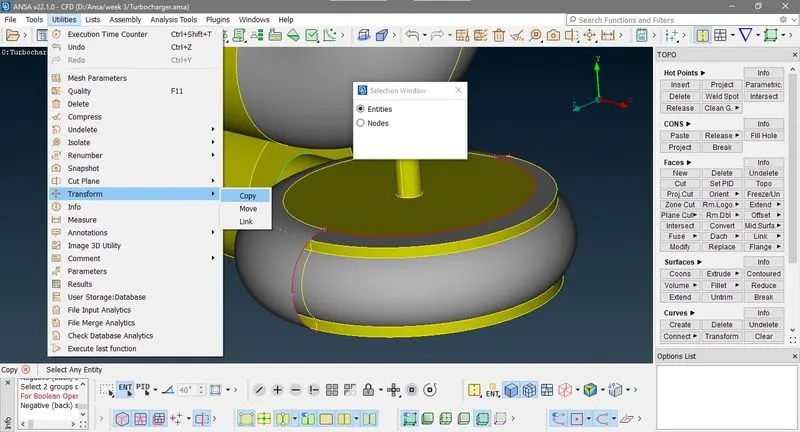
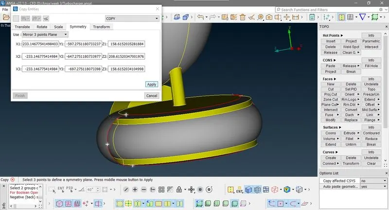
when surface is mirror, there is a hole on surface
Now Go to TOPO > CONS > Fill hole
and select hole
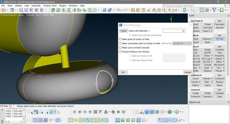
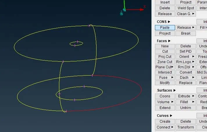
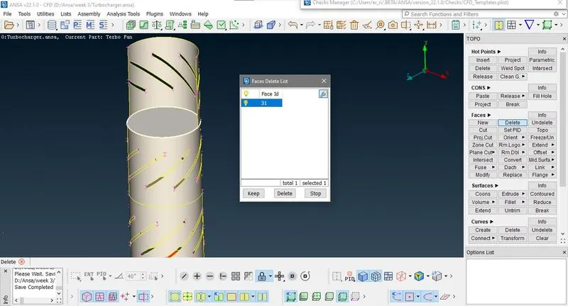
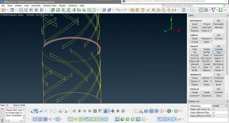
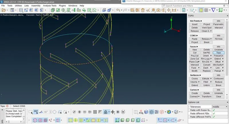
Now if you go to check geometry it show red cons on upper and bottom edge of surface , this is becaue the mirror surface not overlaping with top and bottom faces so it show four red cons in warning and 2 error of breaking cons. To resolve this what we have to do ,first off shadow mode and go to TOPO>Faces>TOPO (for Topo clean up) ,now select single con on top press scrole of mouse, then againg select that and press scrole of mouse again. Now you see you single cons became a a single double con. Do same for bottom edge.
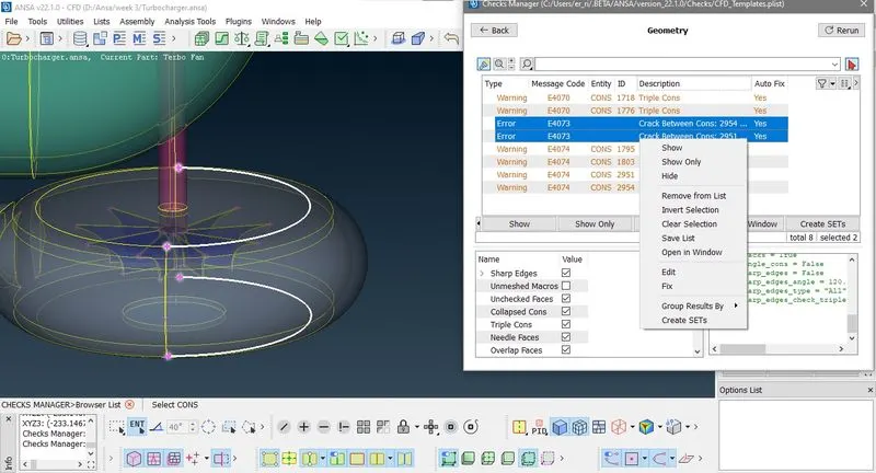
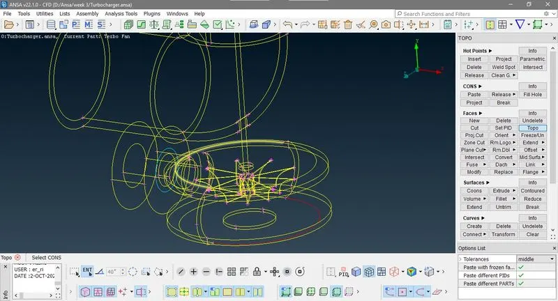
you can also use TOPO>CONS>Paste
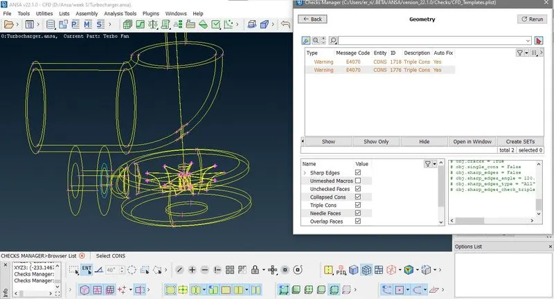
Step 8:- Now here only triples cones are there which is at intersection of inlet casing cover to compressor casing. This can be ignore.
Now If we see intersection error in impeller sleeves and shaft.
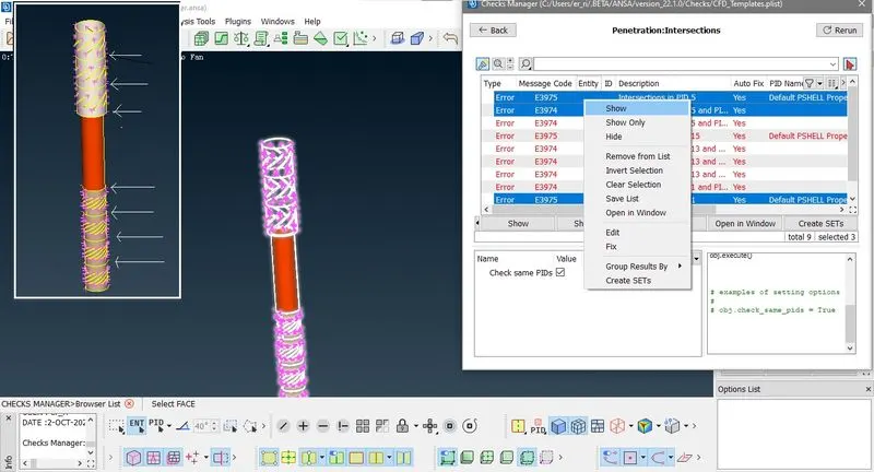
Here impeller hubs boundaries are intersecting each other first we click Show only It show only those part are intersecting lock it. Now hide sleeve face and delete falt face. After deleting it you see single con on sleeve then to to TOPO clean up select single cone >press mid of mouse > again select double cone of next sleeve.Now our single con gone and a triple con is showing which can be ignore. Do same procedur for all impeller sleeve.
Step 9:- After clear intersection error on all impeller's sleeve now we cleare intersection error on shaft and hub of impeller.
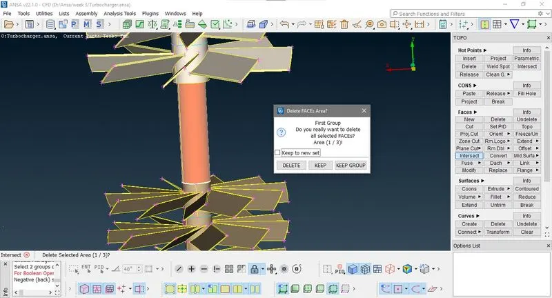
Go to TOPO> Faces>Intersect > select firts and second surface, press scrole and chosse wich surface in to keep or delete.
Step 10:- Now this inter section of shat on sleeve
first go to TOPO > CONS > Project select cons on sleeve press scrole and click surface of shaft
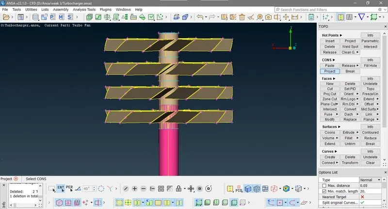
now got to delete abd delete this intersecing face
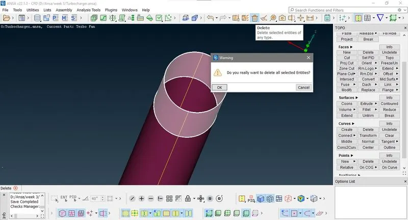
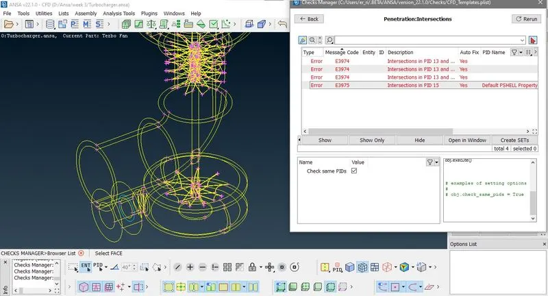
Step 11:- Now if you ckeck geometry it show warnning of triple cons which can ignore and if you see intersection error it shwon intersection of inlet cover and copressor casing. Now shaded mode on hide other thing select those face and delete them
Step 12:- Now see intesection of turbo casing to shaft . IF uyou use intersect option it show 110 face to delete or keep so we jus delete inside surface of hole in casing.
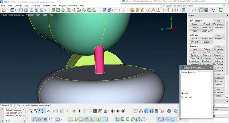
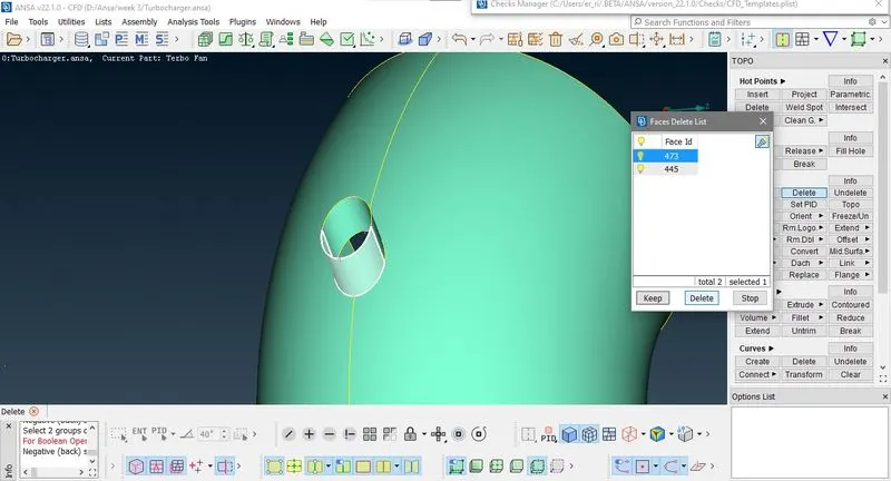
Now t o delete portion of shaft i use project
TOPO> CONS> Project Select cons of casing and select face of shaft.Then delete insesecting part of shaft.
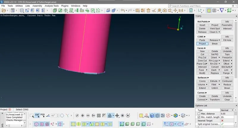
Step 13:- Here shaft end is interseting impelere base. You cant delete impeler face directly first go to TOPO> CONS> Project Select end cons of shaft and select end face of impeller.And delete the face of impeler hub only it never deleting balde faces.
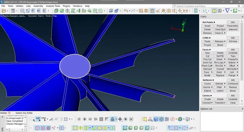
Step 14:- Now we show shaft and comperasor faces of intersection LOCK it and go to project and select cons and select shaft face.
after projecting cons on shaft delete the intersecting part.
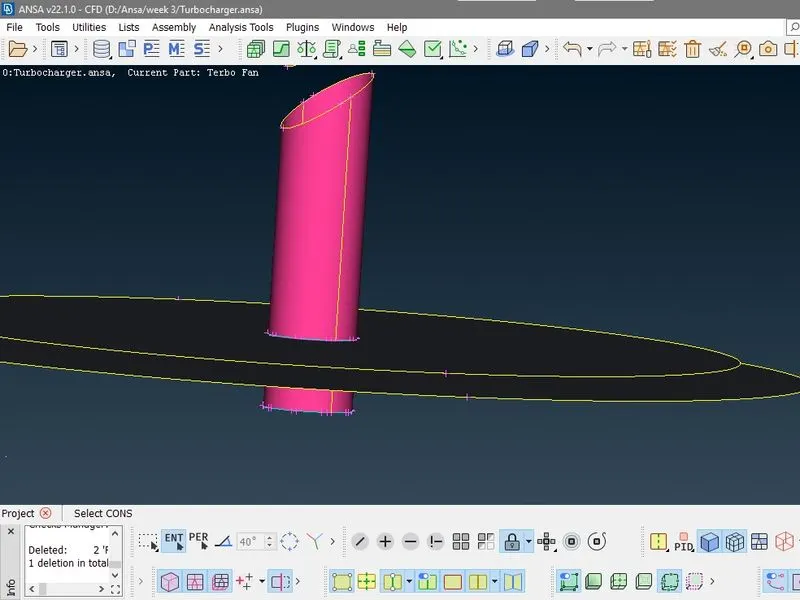
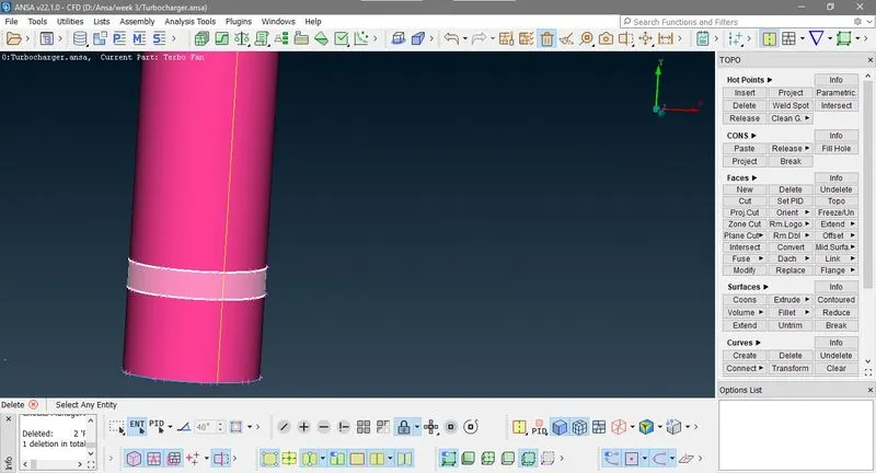
Step 15 :- Now chech geometry here no intersection and penitration error and only geomery error due to triple cones are there
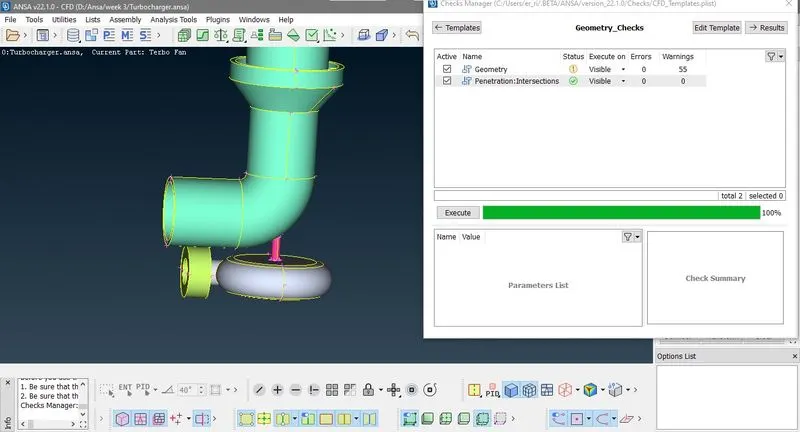
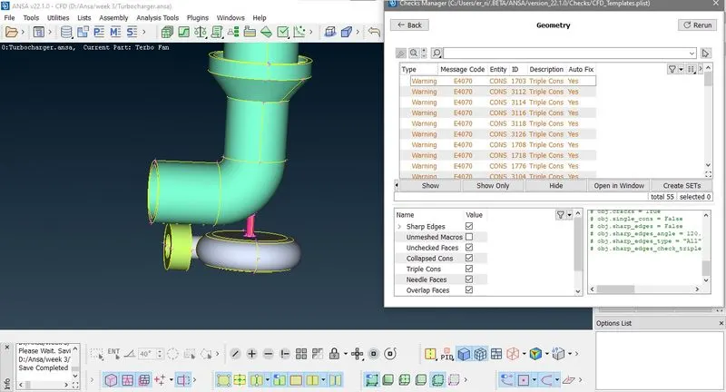
Step 16: close all inlet and oulet with help of cons and fitted
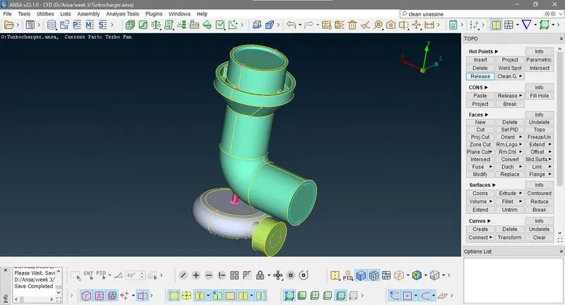
II) Apply PID on geometry and name them
First open properites or go to set PID
Hide all PID only imeler of turbine is shown now right click > Edit > rename to balde stage 1. do this for all PID.
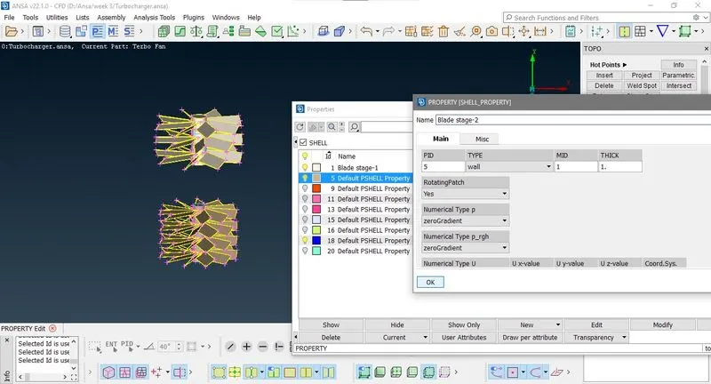
Now look here shaft has two PID . Select any of them in list Right click> Apply> select face of othere PID Geometry.
Now you can see othe PID is auto hided. and edit selected PID change its name to shaft.
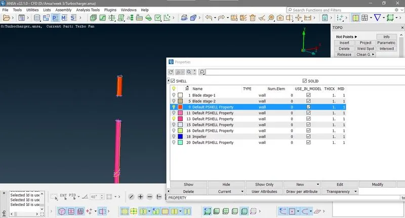
Now delete unasine PID
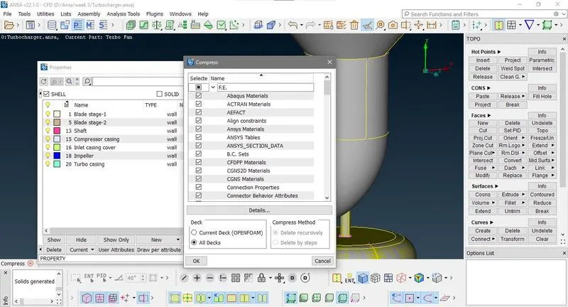
III) 2-D Surface meshing
1) First hide all PID only show shaft, Blade stage-1 and Blade stage-2 only. Because in these bodies target length is 1mm.
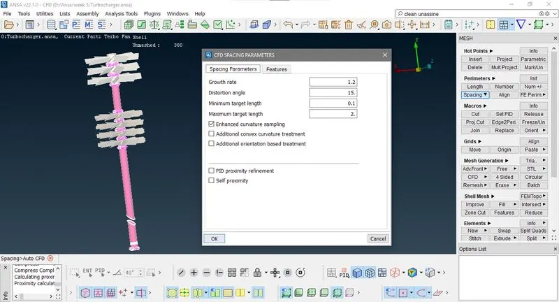
2) Go to Classical mesh > Perimeters >Spacing perimeter box selection all press scrole give value of minmum and maximum target length 0.1 and 2 mm respectivly. do this with macro selectionas shown in image.
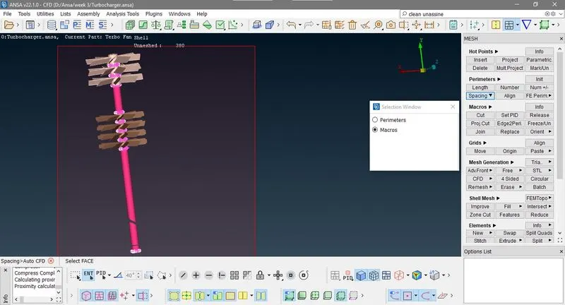
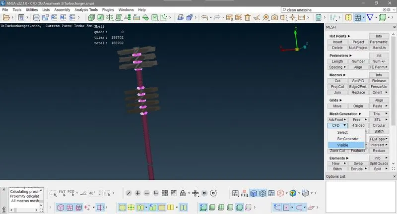
3) Go to Classical mesh >Mesh Generation> CFD>Visible
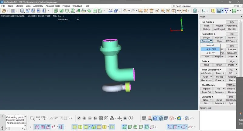
4) Go to Classical mesh > Perimeters >Spacing > perimeter box selection all press scrole give value of minmum and maximum target length 4.1 and 6 mm respectivly.and do this with macro
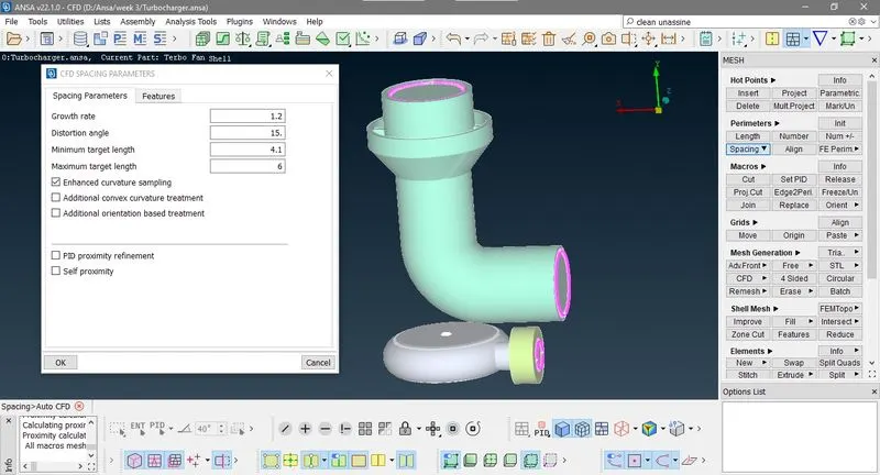
Go to Classical mesh >Mesh Generation> CFD>Visible
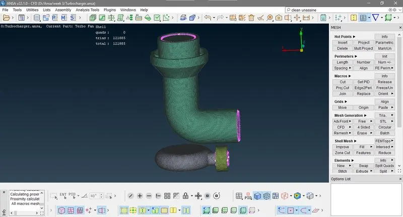
5) Go to Classical mesh > Perimeters >Spacing perimeter box selection all press scrole give value of minmum and maximum target length 1.1 and 3 mm respectivly.and do this with macro
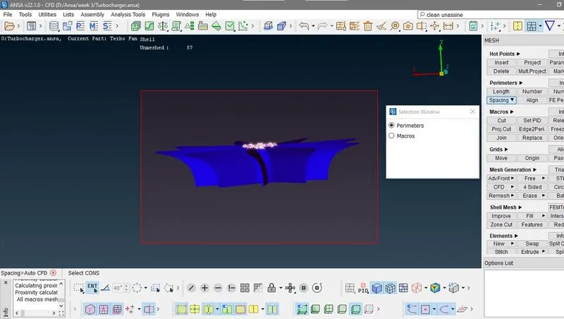
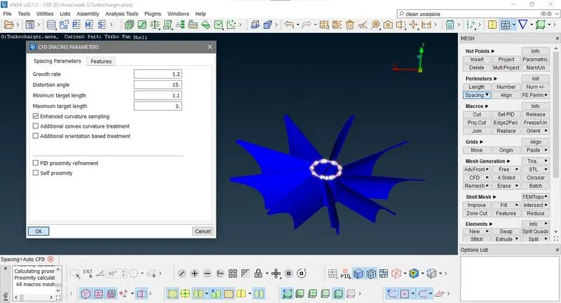
6) Show all you can see unmeshed surface here
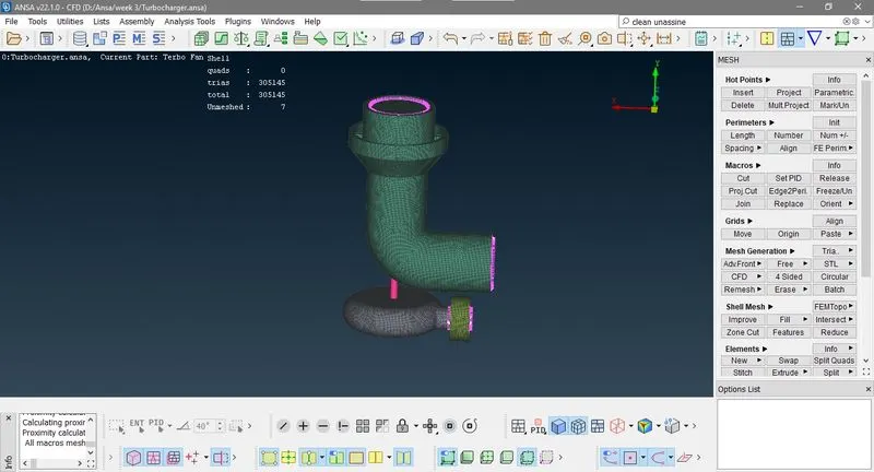
Go to Clasical Mesh > Mesh Generation > free mesh
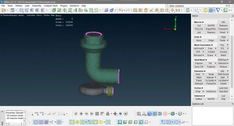
IV) 3-D volume meshing
Step 1: Check detected volumes
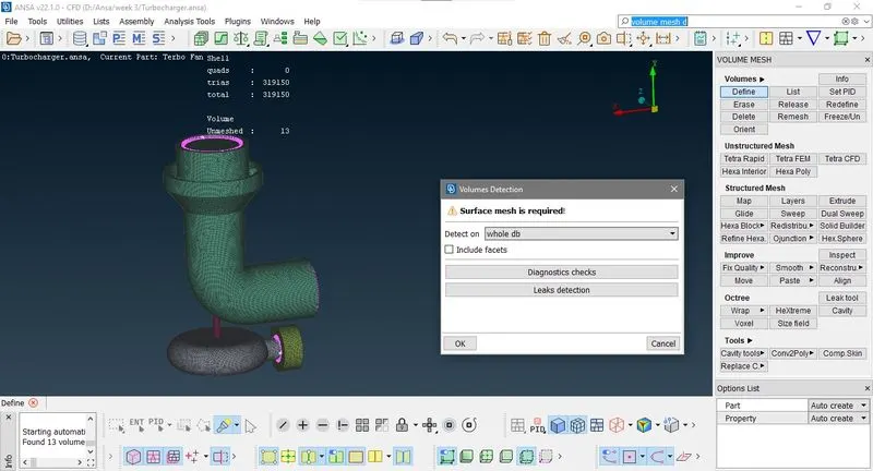
Step 2:- Delete those volume which are not needed.
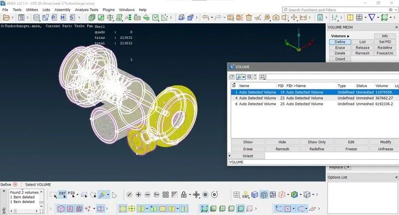
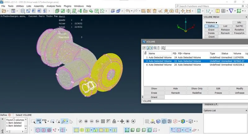
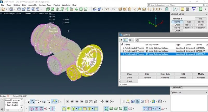
Step 3:-3D Meshing
Now in above images you can see mesh type is undefine and status is unmeshed.so we go to edit
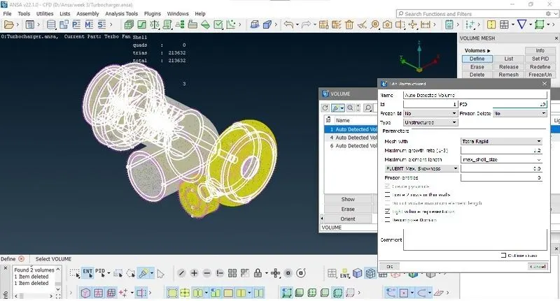
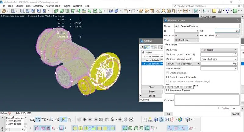
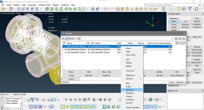
Step 4:- Reameshing all volume
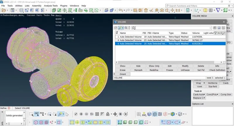
Result check:- Now go to cut plane new > default xy it makes a crosection on xy plane
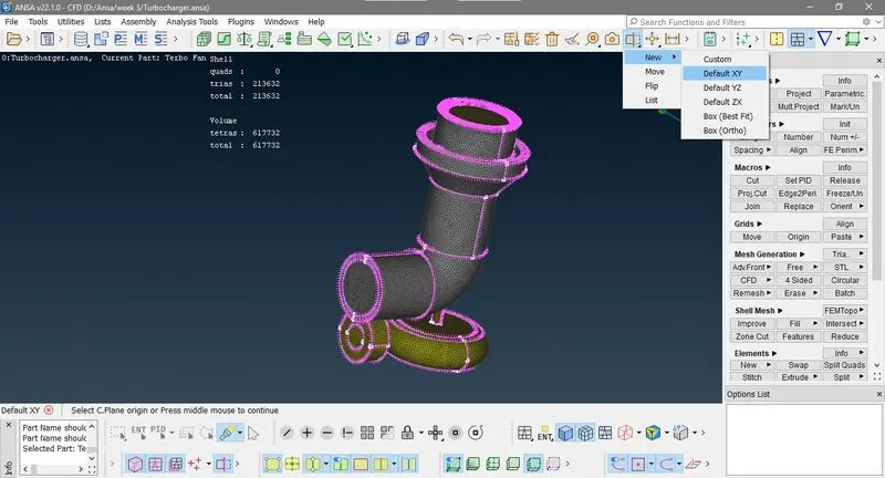
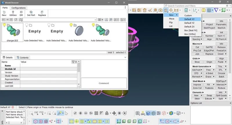
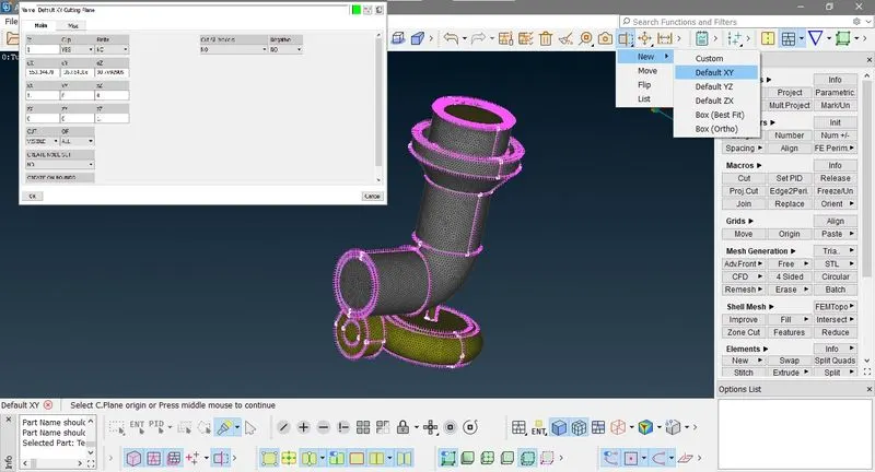
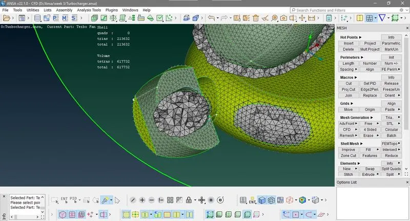
Now you see how 3D mesh is building from surface to core.That why we need to do first surface meshing and then go for volume meshing.
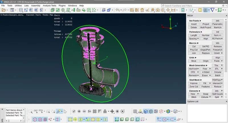
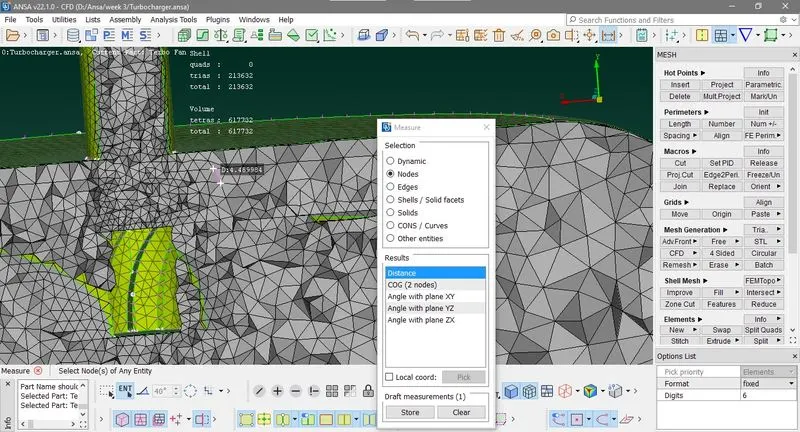
You can measure target length for turbo caseing which is between max and min target length which we define 2 and 8.

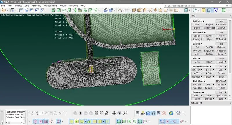
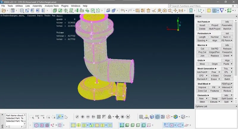
here you can see compressor casing have both 2D and 3D mesh and impellere has ony surface mesh
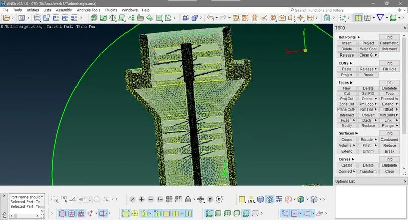
Now hide cut plane and make a new cut plan with acoustom plane by click any 3 points on inlet casing cover to see 3d mesh there
Conclusion:-
1) For 2D meshing of diffrent bodies with different target length there are unmesh element at perimeter (i.e contact boundarie) so we have to frozen those element.
2) Volume meshing can ony done successfully after properly done surface meshing.
3) If there is system memory constrain you have to set refinement of mesh in 2D meshing otherwise ,there is diffuclty in 3D meshing.
4) 3D mesh are bulding as per our 2D mesh from surface to core.