Battery Thermal Management System
Problem Definition:
Perform the heat transfer analysis using ANSYS-Fluent software for the cylindrical Lithium-ion Battery with heat generation boundary conditions. Create an enclosure and use air as the working fluid for cooling the battery back system (4 * 2) Take air inlet temperature as 26°C and space between the batteries as 2 mm.
Property of the Lithium-ion Battery
Nominal Voltage = 3.6 V
Nominal capacity = 2.2A
Density = 2722 kg/m³
Specific heat = 1200 J/kg.K
Thermal Conductivity = 0.2W / m .K
Heat Source = 48750 W/m³ (1.5 C discharge rate)
Size of the Battery = 18mm diameter and 65 mm height.
Aim
To perform an external flow analysis of an automobile battery pack with different flow criteria
Electric Vehicle
An electric vehicle (EV) is a vehicle that uses one or more electric motors for propulsion. It can be powered by a collector system, with electricity from extravehicular sources. It can be powered autonomously by a battery (sometimes charged by solar panels, or by converting fuel to electricity using fuel cells or a generator).[1] EVs include, but are not limited to, road and rail vehicles, surface and underwater vessels, electric aircraft, and electric spacecraft. For road vehicles, together with other emerging automotive technologies such as autonomous driving, connected cars, and shared mobility, EVs form a future mobility vision called Connected, Autonomous, Shared, and Electric (CASE) Mobility, nowadays most of the industry and research engineers works on developing good electric cars and two-wheelers.
How do Electric Vehicles Work?
All-electric vehicles, also referred to as battery electric vehicles (BEVs), have an electric motor instead of an internal combustion engine. The car uses a large traction battery pack to power the electric motor and must be plugged into a wall outlet or charging equipment, also called electric vehicle supply equipment (EVSE). Because it runs on electricity, the vehicle emits no exhaust from a tailpipe and does not contain the typical liquid fuel components, such as a fuel pump, fuel line, or fuel tank.
Key Components of an All-Electric Car
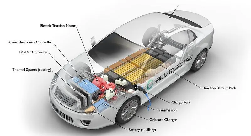
- Battery (all-electric auxiliary): In an electric drive vehicle, the auxiliary battery provides electricity to power vehicle accessories.
- Charge port: The charge port allows the vehicle to connect to an external power supply to charge the traction battery pack.
- DC/DC converter: This device converts higher-voltage DC power from the traction battery pack to the lower-voltage DC power needed to run vehicle accessories and recharge the auxiliary battery.
- Electric traction motor: Using power from the traction battery pack, this motor drives the vehicle's wheels. Some vehicles use motor generators that perform both the drive and regeneration functions.
- Onboard charger: Takes the incoming AC electricity supplied via the charge port and converts it to DC power for charging the traction battery. It also communicates with the charging equipment and monitors battery characteristics such as voltage, current, temperature, and state of charge while charging the pack.
- Power electronics controller: This unit manages the flow of electrical energy delivered by the traction battery, controlling the speed of the electric traction motor and the torque it produces.
- Thermal system (cooling): This system maintains a proper operating temperature range of the engine, electric motor, power electronics, and other components.
Traction battery pack: Stores electricity for use by the electric traction motor. - Transmission (electric): The transmission transfers mechanical power from the electric traction motor to drive the wheels.
While talking about the electric vehicle the important component battery and the thermal management of the batteries.
Battery
A battery is a source of electric power consisting of one or more electrochemical cells with external connections for powering electrical devices. When a battery is supplying power, its positive terminal is the cathode and its negative terminal is the anode The terminal marked negative is the source of electrons that will flow through an external electric circuit to the positive terminal. When a battery is connected to an external electric load, a redox reaction converts high-energy reactants to lower-energy products, and the free-energy difference is delivered to the external circuit as electrical energy. Primary (single-use or "disposable") batteries are used once and discarded, as the electrode materials are irreversibly changed during discharge; a common example is the alkaline battery used for flashlights and a multitude of portable electronic devices. Secondary (rechargeable) batteries can be discharged and recharged multiple times using an applied electric current; the original composition of the electrodes can be restored by reverse current. Examples include the lead–acid batteries used in vehicles and lithium-ion batteries used for portable electronics such as laptops and mobile phones.
Batteries come in many shapes and sizes, from miniature cells used to power hearing aids and wristwatches to, at the largest extreme, huge battery banks the size of rooms that provide standby or emergency power for telephone exchanges and computer data centres. Batteries have much lower specific energy (energy per unit mass) than common fuels such as gasoline. In automobiles, this is somewhat offset by the higher efficiency of electric motors in converting electrical energy to mechanical work, compared to combustion engines commonly known as lithium-ion batteries
Lithium-ion batteries
A lithium-ion or Li-ion battery is a type of rechargeable battery that uses the reversible reduction of lithium ions to store energy. A conventional lithium-ion cell's anode (positive electrode) is typically graphite made from carbon. The cathode (negative electrode) is typically a metal oxide. The electrolyte is typically a lithium salt in an organic solvent. It is the predominant battery type used in portable consumer electronics and electric vehicles. It also sees significant use for grid-scale energy storage and military and aerospace applications. Compared to other rechargeable battery technologies, Li-ion batteries have high energy densities, low self-discharge, and no memory effect (although a small memory effect reported in LFP cells has been traced to poorly made cells).
Chemistry, performance, cost and safety characteristics vary across types of lithium-ion batteries. Most commercial Li-ion cells use intercalation compounds as active materials. The anode or positive electrode is usually graphite, although silicon carbon is also being increasingly used. Cells can be manufactured to prioritize either energy or power density may offer longer lives and may have better rate capability. NMC and its derivatives are widely used in the electrification of transport, one of the main technologies (combined with renewable energy) for reducing greenhouse gas emissions from vehicles and if those batteries can be a safety hazard if not properly engineered and manufactured since cells have flammable electrolytes and if damaged or incorrectly charged, can lead to explosions and fires. Much development has made progress in manufacturing safe lithium-ion batteries.
Problem with lithium batteries
All lithium-ion batteries use flammable materials, and incidents such as the one in the Bronx are likely the result of "Thermal runaway," a chain reaction that can lead to fire because a typical lithium-ion battery stores 150 watt-hours of electricity in 1 kilogram of battery, compared to NiMH Battery pack (100 watt-hours per kg) or Lead Acid Battery (25 watt-hours per kg). It takes 6 kilograms to store the same amount of energy in a lead-acid battery that a 1-kilogram lithium-ion battery can handle. However, lithium-ion batteries are extremely sensitive to high temperatures and inherently flammable. These battery packs tend to degrade much faster than they usually would, due to heat. If a lithium-ion battery pack fails, it will burst into flames and can cause widespread damage.
C-rate
The C-rate is a unit to declare a current value that is used for estimating and/or designating the expected effective time of the battery under variable charge/discharge conditions.
Thermal runaway
It is a chain reaction within a battery cell that can be very difficult to stop once it has started. It occurs when the temperature inside a battery reaches the point that causes a chemical reaction to occur inside the battery. This chemical reaction produces even more heat, which drives the temperature higher, causing further chemical reactions that create more heat. In thermal runaway, the battery cell temperature rises incredibly fast (milliseconds). The energy stored in that battery is released very suddenly. This chain reaction creates extremely high temperatures (around 752 degrees Fahrenheit / 400 degrees Celsius). These temperatures can cause gassing of the battery and a fire that is so hot it can be nearly impossible to extinguish.
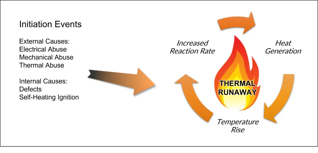
The major reasons for thermal runaway are
- An internal short circuit is caused by physical damage to the battery or poor battery maintenance.
- Overcharging a battery beyond its safe max voltage.
- Due to the redox reactions, it creates heat so it requires a cooling system for continuous use.
Rapid heat propagation from one damaged cell to another cell causes a huge fire.
Hear the project is based on the cooling system of the battery and to increase the capacity and voltage the battery is connected in series and parallel, in this case, a 2*4 battery pack is used for the analysis.
Battery Thermal Management System (BTMS)
A battery thermal management system controls the operating temperature of the battery by either dissipating heat when it is too hot or providing heat when it is too cold. Engineers use active, passive, or hybrid heat transfer solutions to modulate battery temperature in these systems. Active solutions typically have a fan or pump pushing working fluid—such as air, water, or some other liquid—to reduce or increase battery temperature. In a passive solution, either heat sinks or pipes with thermally conductive materials transfer heat away from the battery. A hybrid solution combines key design features of both active and passive solutions.
In this case, air cooling has been used to analyse the 2*4 battery load with 1.5 C.
Procedure
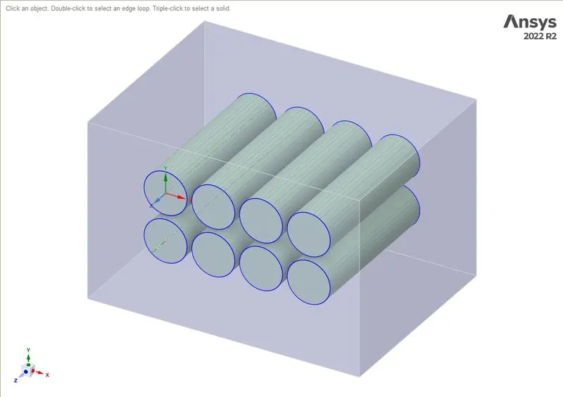
Step 1: Initially, start with creating the geometry in SpaceClaim and prepare it for a flow-over analysis.
- Start with creating a circle with an 18 mm diameter and use the pull command with a 65 mm length to create a cylinder.
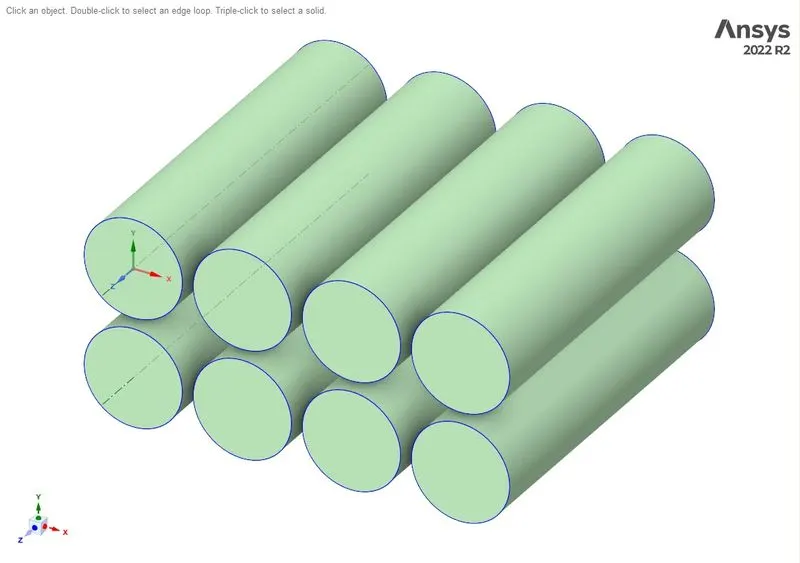
- with the cylinder use a patent to create multiple cylinders.
- Create an enclosure for those cylinders the enclosure dimensions from the four sides will be 18mm and from the top and bottom, it will be 10 mm.
I use script recording and then reused it for all other cases by changing the gap value.
ClearAll()
Gap=MM(2)
# Set Sketch Plane
sectionPlane = Plane.PlaneXY
result = ViewHelper.SetSketchPlane(sectionPlane, Info2)
# EndBlock

# Sketch Circle
origin = Point2D.Create(MM(0), MM(0))
result = SketchCircle.Create(origin, MM(9))

baseSel = SelectionPoint.Create(CurvePoint1)
targetSel = SelectionPoint.Create(DatumPoint1)

result = Constraint.CreateCoincident(baseSel, targetSel)
# EndBlock

# Solidify Sketch
mode = InteractionMode.Solid
result = ViewHelper.SetViewMode(mode, Info3)
# EndBlock

# Extrude 1 Face
selection = Face1
options = ExtrudeFaceOptions()
options.ExtrudeType = ExtrudeType.Cut
result = ExtrudeFaces.Execute(selection, MM(-65), options, Info4)
# EndBlock
A=MM(18)+Gap
# Create Pattern
selection = Body1
data = LinearPatternData()
data.PatternDimension = PatternDimensionType.Two
data.LinearDirection = Axis1
data.CountX = 4
data.PitchX =A
data.CountY = 2
data.PitchY = A
result = Pattern.CreateLinear(selection, data, Info5)
# EndBlock

# Create Enclosure
selection = PatternMembers1

options = EnclosureOptions()
options.EnclosureType = EnclosureType.Box
options.EnclosureCushion = BoxEnclosureCushion(MM(18),MM(18),MM(18),MM(18),MM(10),MM(10))
result = Enclosure.Create(selection, options)
# EndBlock

# Share Topology
options = ShareTopologyOptions()
options.Tolerance = MM(0.2)
options.PreserveInstances = False
result = ShareTopology.FindAndFix(options, Info6)
# EndBlock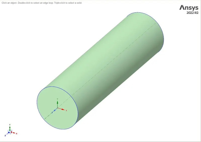
Step 2: From the created geometry mesh the surface with Tetra mesh elements and create inflation with the cylinder wall sizes, after creating the mesh or before making the mesh name the surfaces as per the boundary condition so that the fluent can recognize the boundary condition itself.
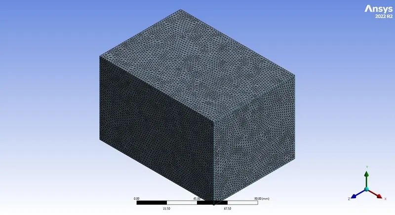
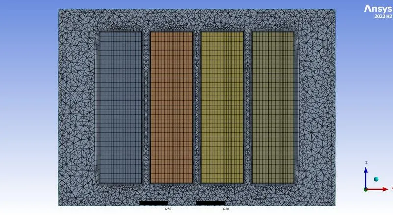
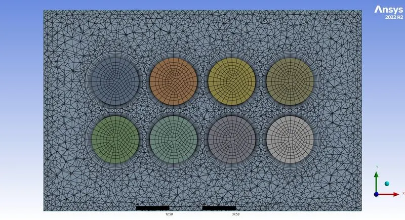
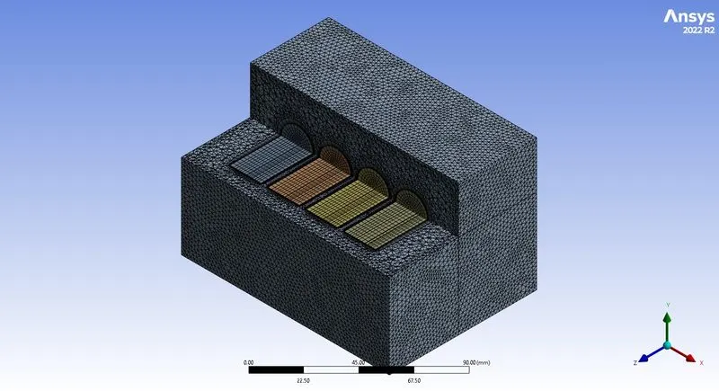
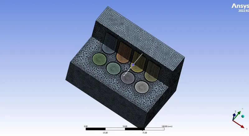
After generating the mesh, the number of nodes and elements is investigated using the statistics option. Then the mesh quality is checked by choosing the mesh matrices option in the quality section.
Step 3:In this step, the meshed geometric file has been imported to the fluent module and set the following conditions as follows in the fluent in solving the problem.
This procedure will be constant for the short tee and long tee with a momentum ratio
|
SOLVER TYPE |
Pressure based |
|
VELOCITY FORMULATION |
Absolute |
|
TIME |
Steady |
|
VISCOUS MODEL |
K omega sst |
|
MATERIAL |
Fluid: air Solid:
|
|
CELL ZONES |
Fluid: air Battery solid: lithium with constant heat generation of 48750 W/m³ (1.5 C discharge rate) External enclosure surface: acrylic |
|
BOUNDARIES (depends on the momentum ratio) |
Inlet_x (velocity inlet) 2,5and 10 m/s constant temperature of 300 k Outlet: pressure outlet Battery walls: Stationary walls Enclosure Wall: Stationary wall with convective heat transfer of 5 w/(m2k |
|
Report definition |
|
The hybrid scheme is used for the initialization.
Results
Coarse mesh
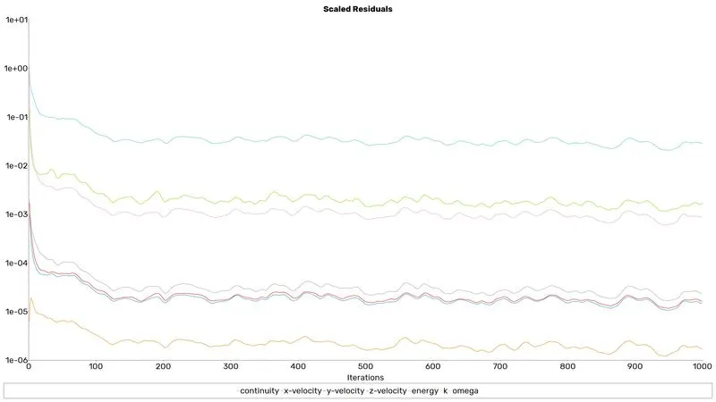
Residuals
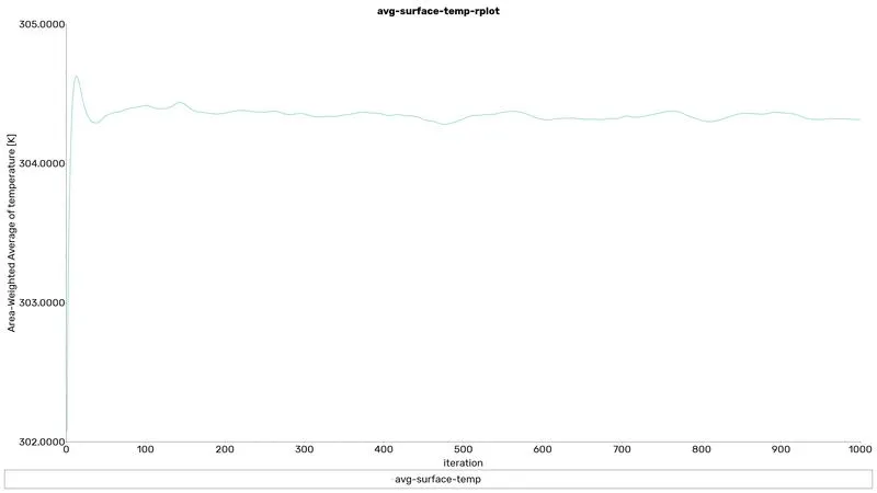
avg-surface-temp
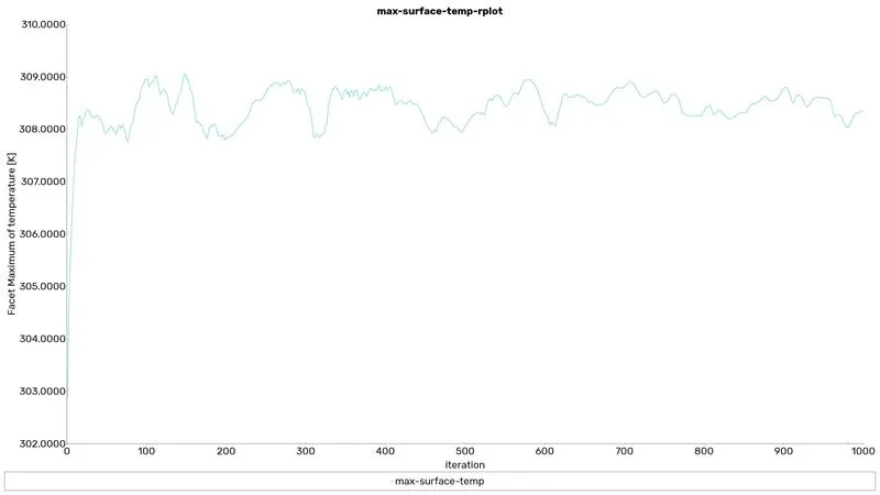
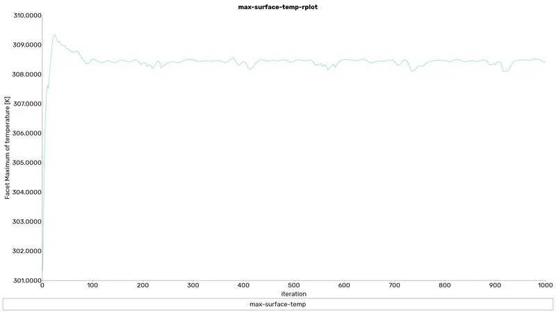
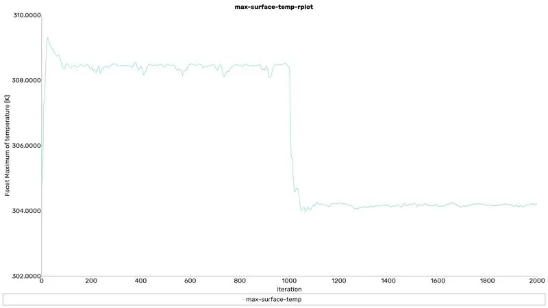
max-surface-temp
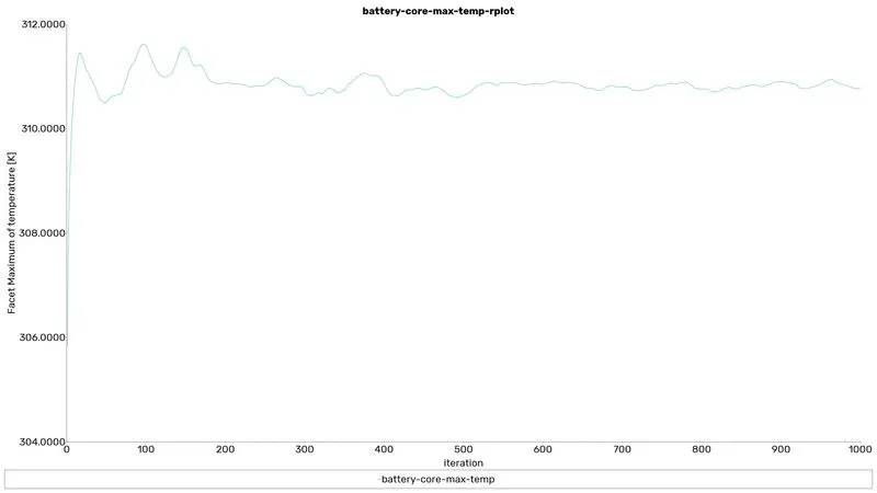
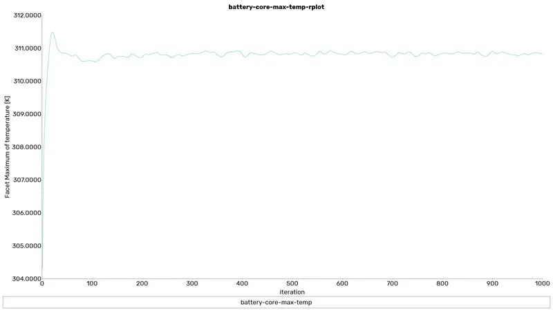
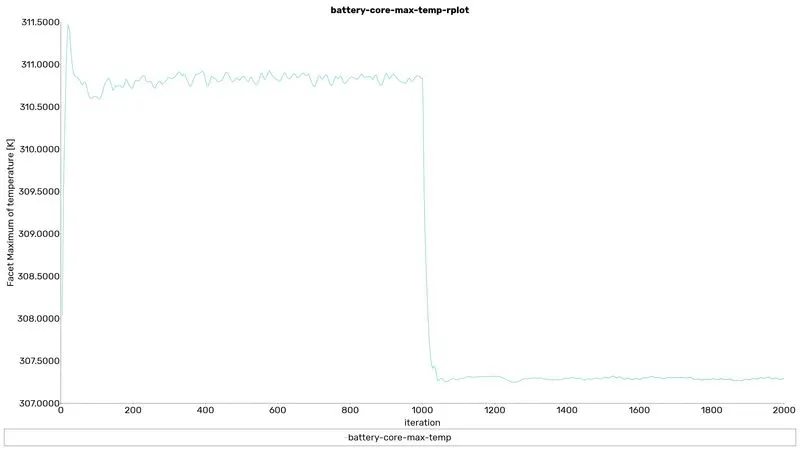
battery-core-max-temp
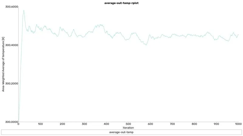
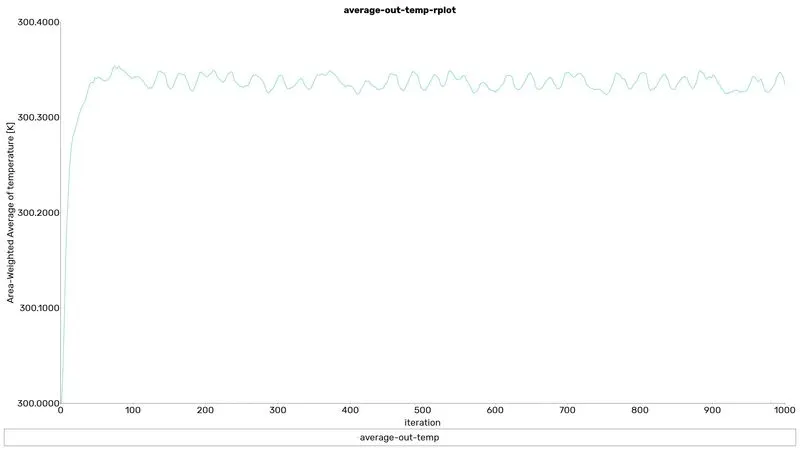
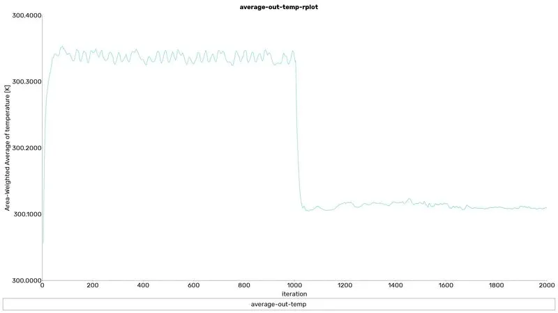
average-out-temp
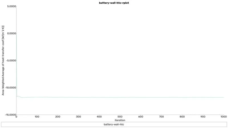
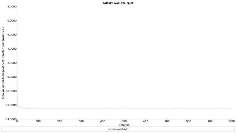
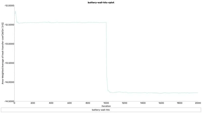
battery-wall-htc
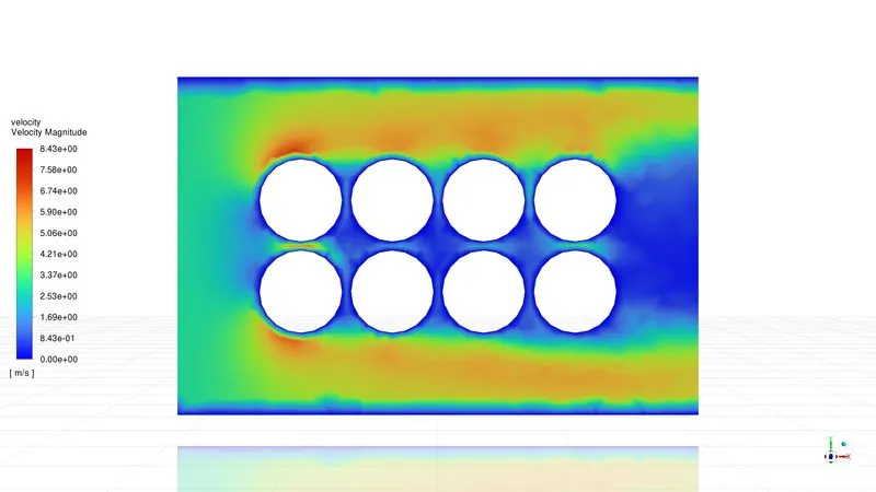
velocity contour
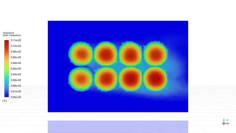
Temperature contour
Fine mesh
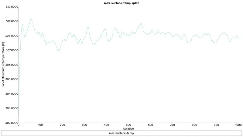
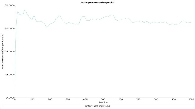
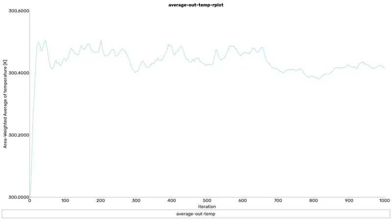
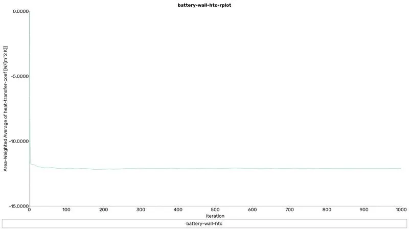
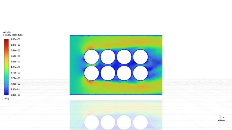
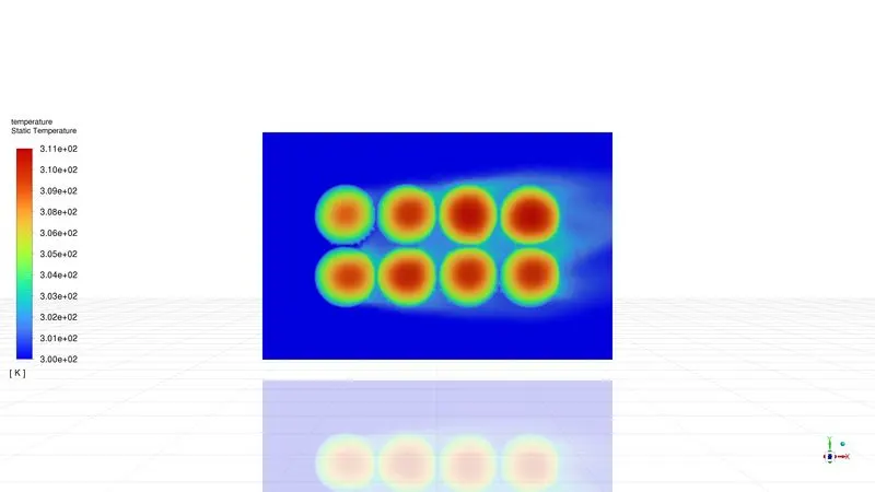
Case 1: The gap between the battery is 2mm And velocity = 3m/s
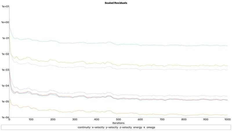
Residuals
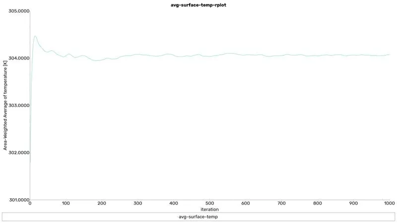
avg-surface-temp
max-surface-temp
battery-core-max-temp
average-out-temp
battery-wall-htc
velocity contour
temperature contour
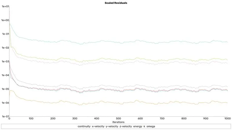
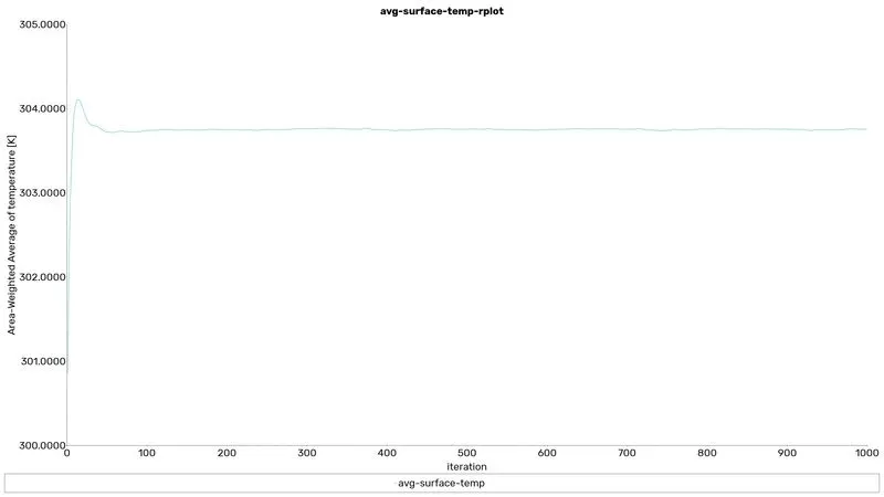
Case 2: The gap between the battery is 4mm And velocity = 3m/s
Residuals
avg-surface-temp
max-surface-temp
battery-core-max-temp
average-out-temp
battery-wall-htc
velocity contour
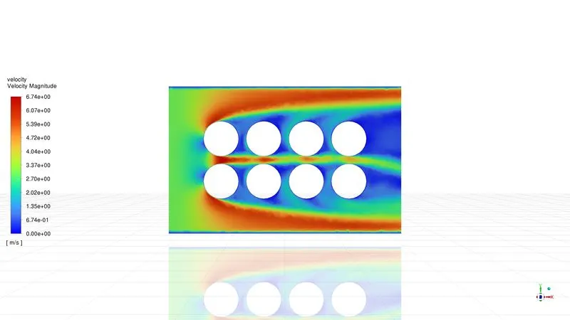
temperature contour
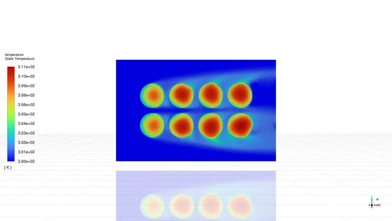
Case 3: The gap between the battery is 6mm And velocity = 3m/s
Residuals
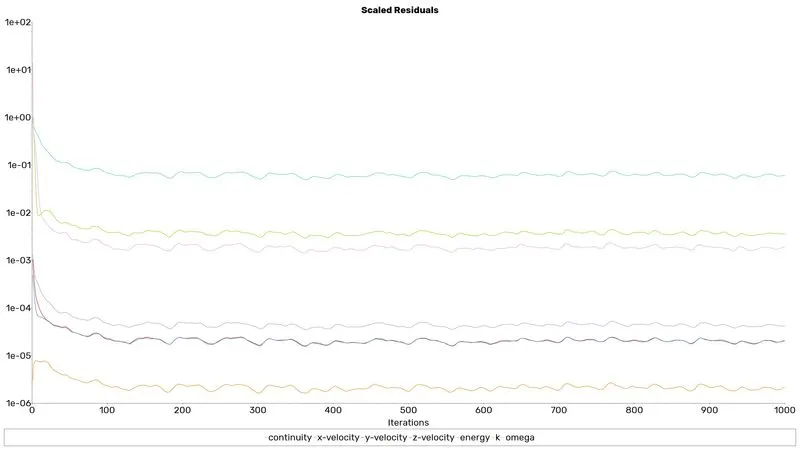
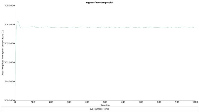
avg-surface-temp
max-surface-temp
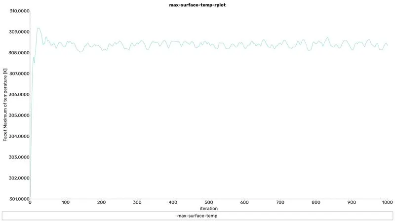
battery-core-max-temp
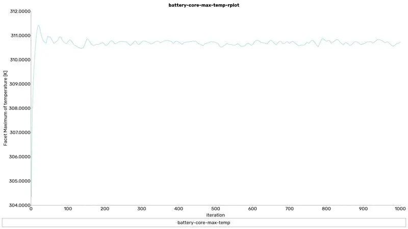
average-out-temp
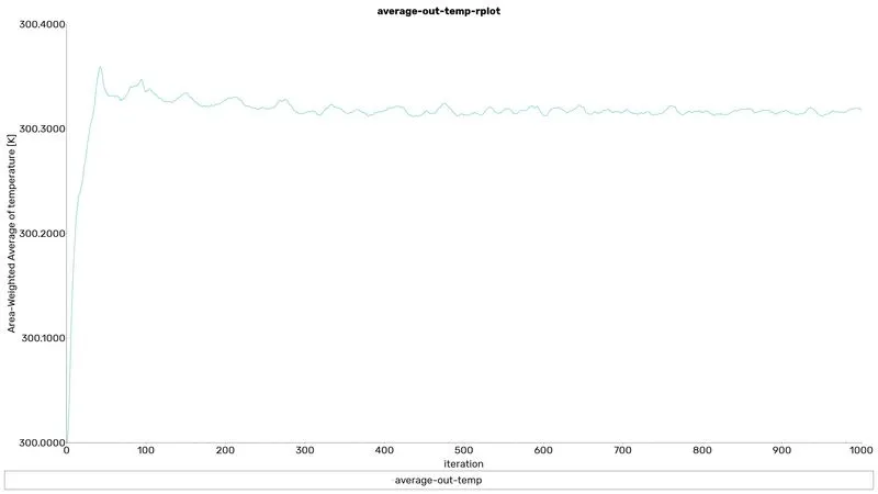
battery-wall-htc
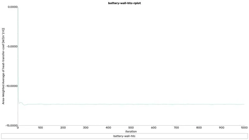
velocity contour
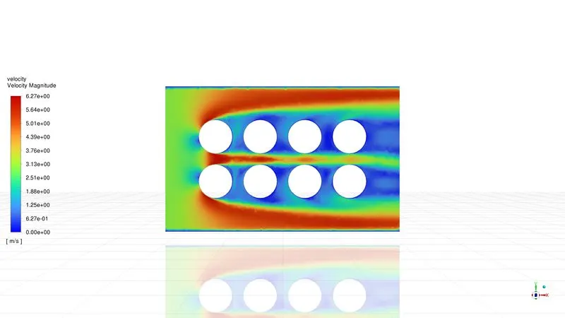
temperature contour
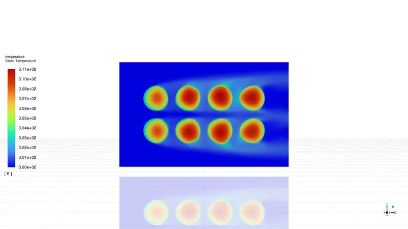
Case 4: The gap between the battery is 4mm And velocity = 5m/s
Residuals
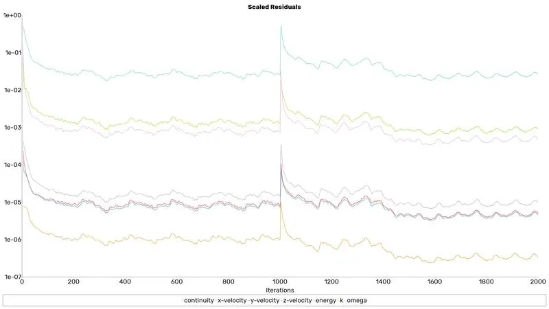
avg-surface-temp
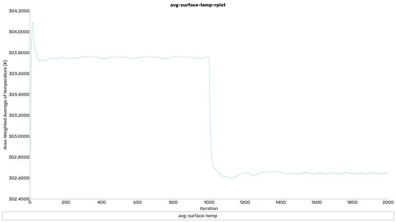
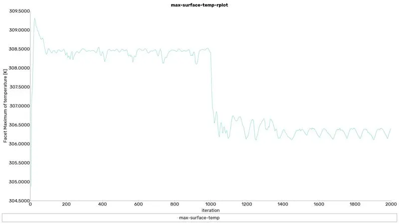
max-surface-temp
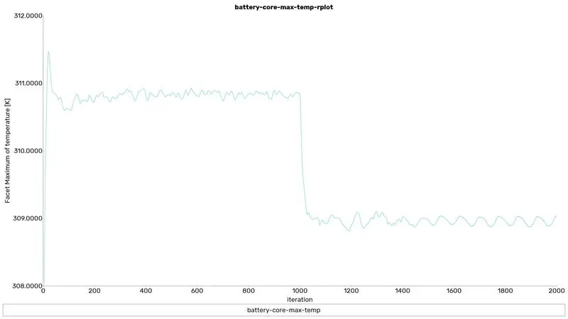
battery-core-max-temp
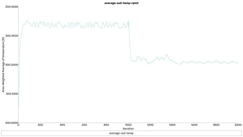
average-out-temp
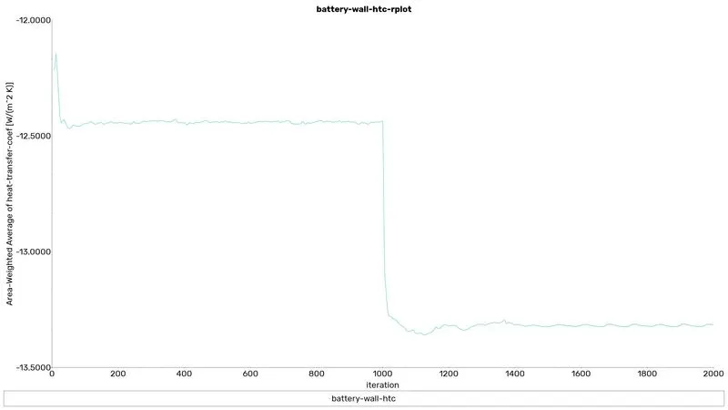
battery-wall-htc
velocity contour
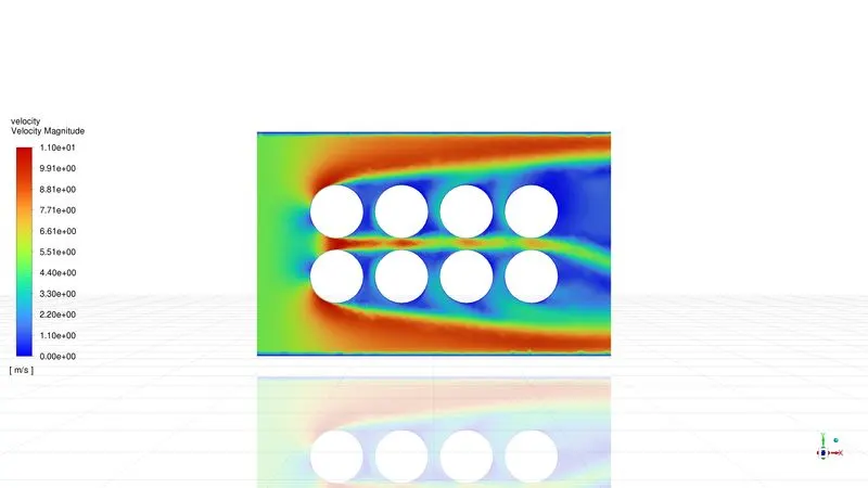
temperature contour
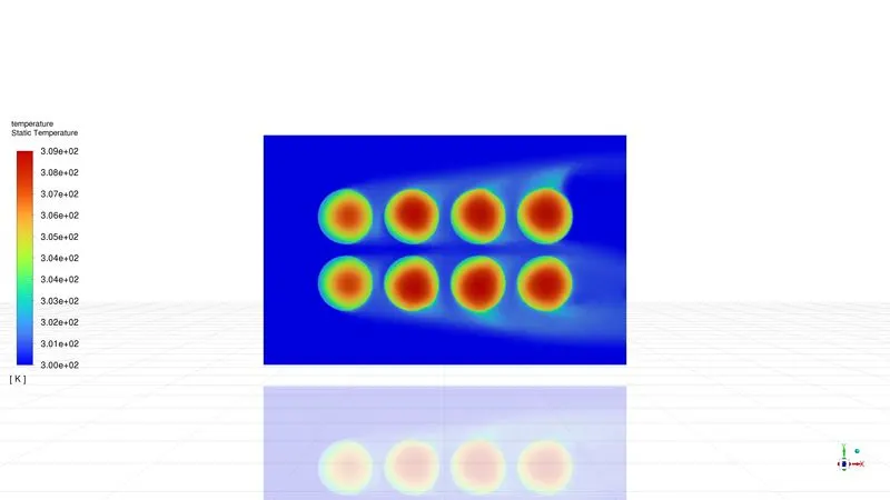
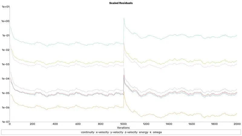
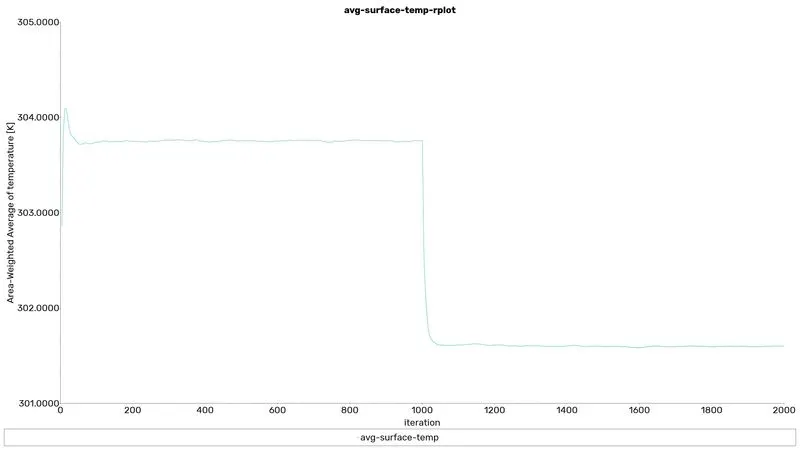
Case 5: The gap between the battery is 4mm And velocity = 10m/s
Residuals
avg-surface-temp
max-surface-temp
battery-core-max-temp
average-out-temp
battery-wall-htc
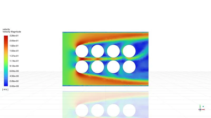
velocity contour
temperature contour
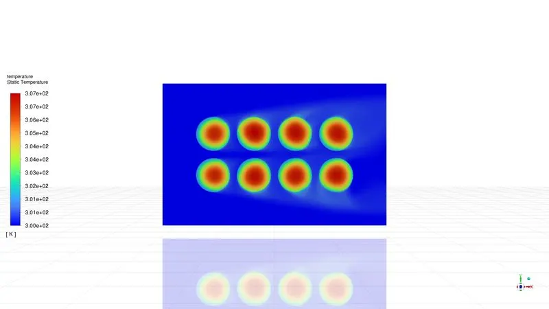
In cases 2,4 and 5 parametric study has been used that's the reason the graphs continued from the previous parameters.
Transient State Analysis
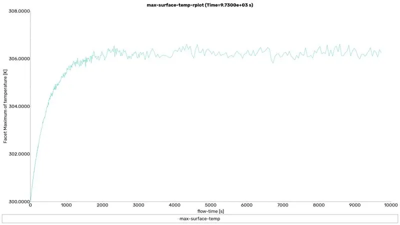
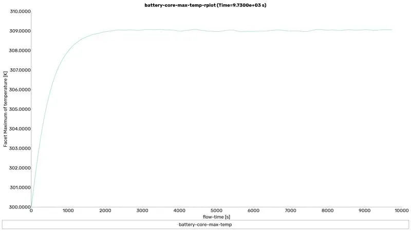
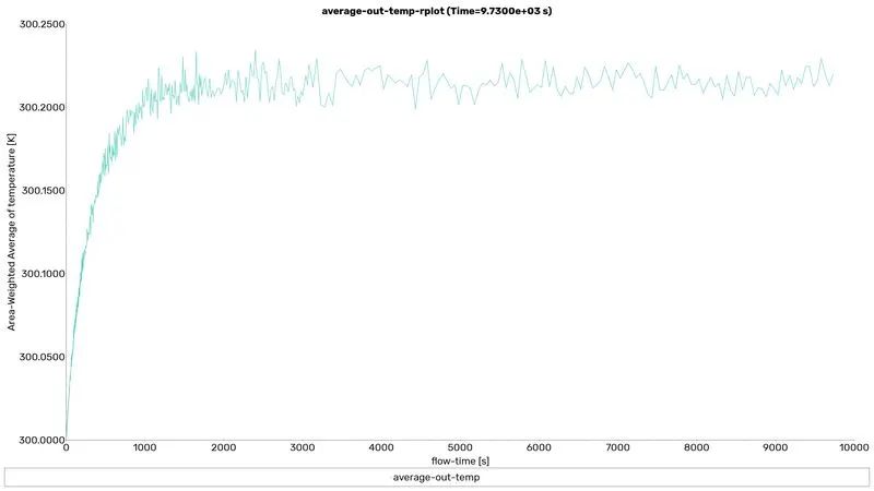
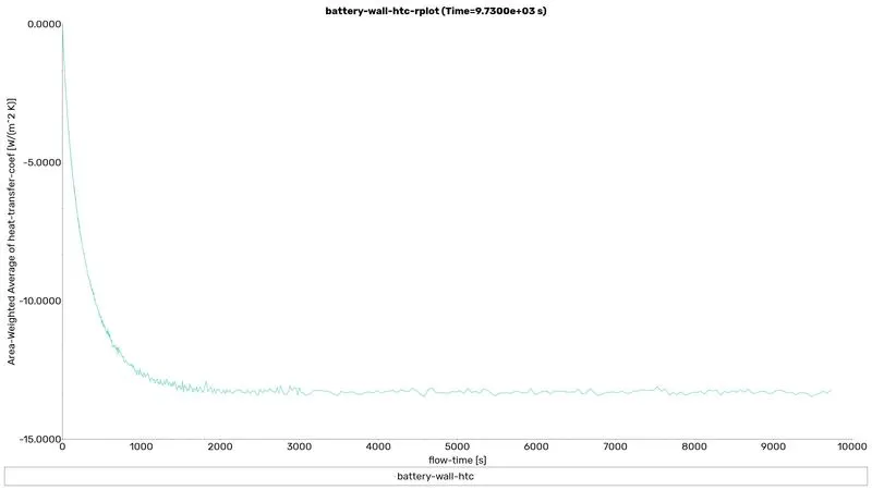
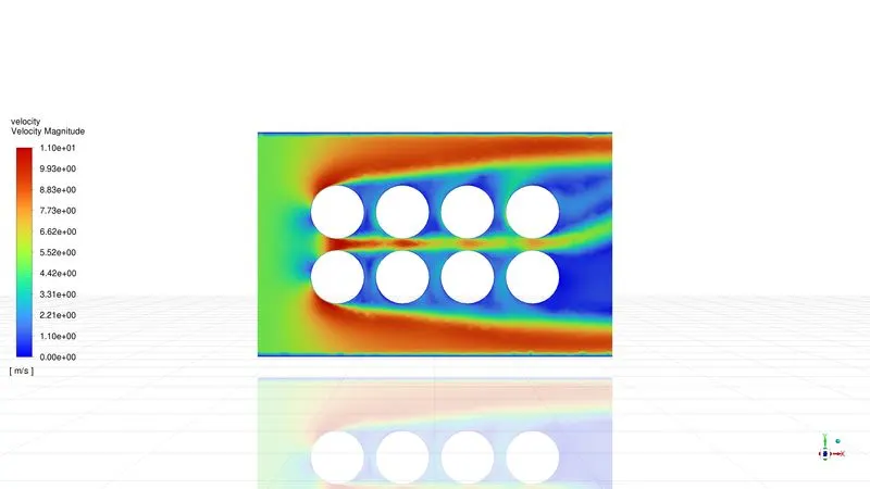
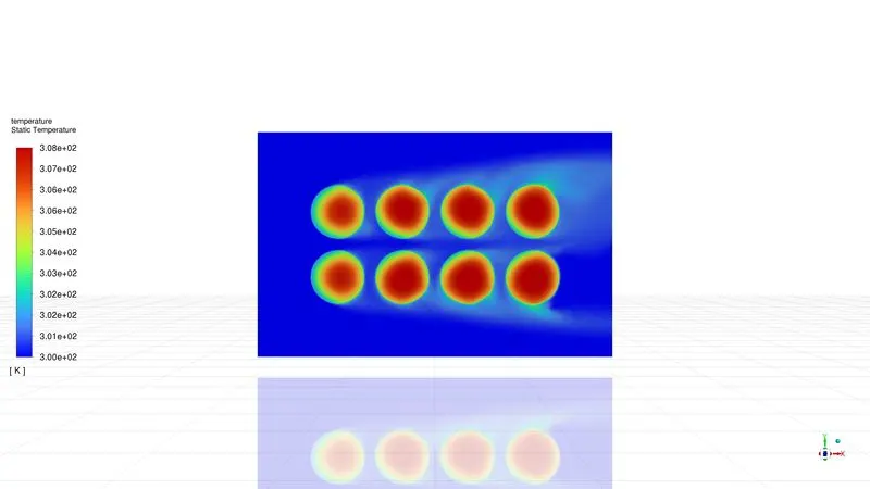
The gap between the battery is 4mm And velocity = 5m/s
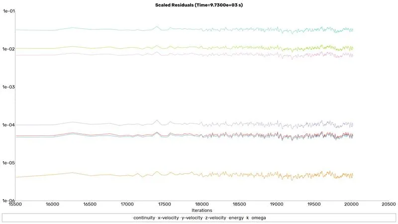
Residuals
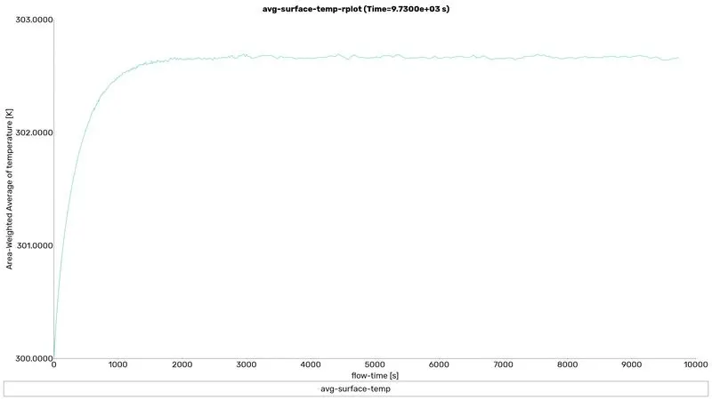
avg-surface-temp
max-surface-temp
battery-core-max-temp
average-out-temp
battery-wall-htc
velocity contour
temperature contour
Animation file
This animation film was obtained with a transient solver.
Solution discussion
| Space between the battery | Inlet_velocity [m/s] | avg-surface-temp-op [K] | max-surface-temp-op [K] | battery-core-max-temp-op [K] | average-out-temp-op [K] | battery-wall-Htc-op [W m^-2 K^-1] |
| 2 | 3 | 304.07392 | 307.83423 | 310.53618 | 300.4179 | -12.0878 |
| 4 | 3 | 303.75776 | 308.40759 | 310.8393 | 300.3341 | -12.4367 |
| 4 | 5 | 302.64925 | 306.39667 | 309.0304 | 300.2065 | -13.317 |
| 4 | 10 | 301.59973 | 304.21924 | 307.2898 | 300.1097 | -14.2779 |
| 6 | 3 | 303.8665 | 308.3709 | 310.7295 | 300.3181 | -12.32 |
- From the table, 10 m/s with 4 mm spacing gives the best heat transfer rate.
- By comparing all the cases the temperature drop is inversely proportional to the gap and velocity of air.
- Adding more space between the battery is also useless and it increases the size of the battery pack.
- Increasing the velocity of fluid flow increases the heat transfer but after a further increase in velocity, there is no any change.
- From the obtained results it will be clear that for a good heat transfer,r we need to maintain perfect space and speed for effective heat transfer.