Week 10 - Simulating Combustion of Natural Gas.
AIM: -
Combustion Simulation of Natural gas inside a Burner using ANSYS FLUENT.
Objective: -
- To study the combustion Phenomenology for the whole problem.
- To study the eddy dissipation model.
- To study the NOx and soot formation inside the burner.
- To pre-process the geometry for the simulation.
- To select correct element size and type for the simulation.
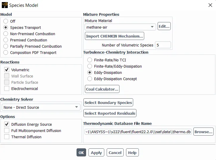
- To setup the combustion simulation using eddy dissipation model.
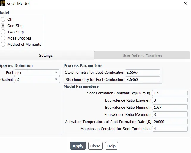
- To setup NOx and soot formation model in simulation.
- To plot the mass fraction of CO2, H2O, CH4, N2, O2, NOx and soot formation.
- To perform the simulation by adding water with fuel in range of 5% to 30% to lower the NOx and soot formation in combustion.
Geometry :-
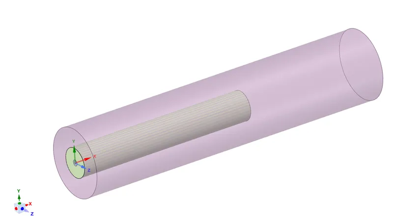
Figure 1- 3D View of Burner
2.1 Geometry Clean-up
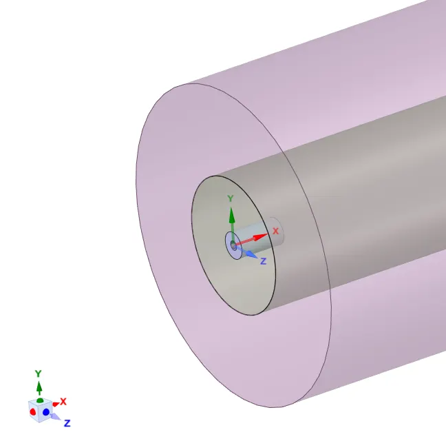
The geometry clean-up is done for the burner 3D model. As it required to create 2D model from provided geometry of burner. The model will directly open in space-claim design modeler and planes are created at the center point of geometry which is shown in below:
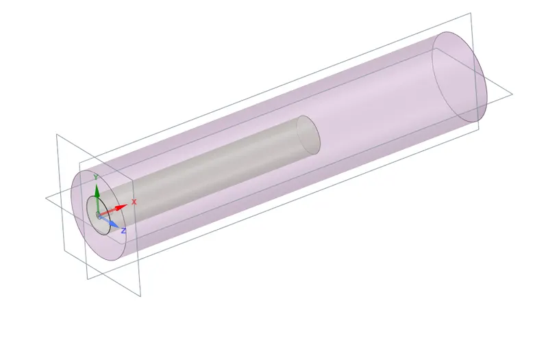
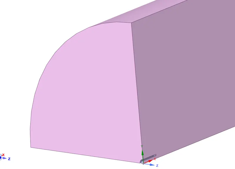
Creation of plane allows to split the body in half or in quarter portion. As for 2D Axisymmetric model it required to cut in quarter model and then the face of that quarter section is copied and pasted in new design. Before copying the face of quarter section, it is required to combine the two section of geometry which are present in whole assembly. Both the geometry instead of fuel opening area can be treated as one body. After creation plane the split body option from space-claim design tab is used to cut the body in half first parallel to XY plane and then it need to be cut parallel to ZX plane. After completion of both splitting only quarter part is required rest of part need to be deleted. The quarter section of geometry is shown in figure 4:
Creation of plane allows to split the body in half or in quarter portion. As for 2D Axisymmetric model it required to cut in quarter model and then the face of that quarter section is copied and pasted in new design. Before copying the face of quarter section, it is required to combine the two section of geometry which are present in whole assembly. Both the geometry instead of fuel opening area can be treated as one body. After creation plane the split body option from space-claim design tab is used to cut the body in half first parallel to XY plane and then it need to be cut parallel to ZX plane. After completion of both splitting only quarter part is required rest of part need to be deleted. The quarter section of geometry is shown in figure 4:
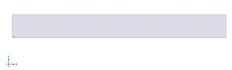
From the quarter section shown in figure 4, the front face of geometry can be used for simulation. To have the face for simulation it is necessary to select the face and copy it. After copying the face from geometry, it has to be pasted in new design which can be made from File>New>Design option. The geometry must be pasted only in XY plane for the sake of Axi-symmetric approach. Figure 5 shows the final geometry for simulation.
Meshing & Named Selection:-
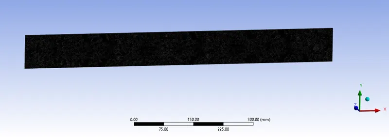
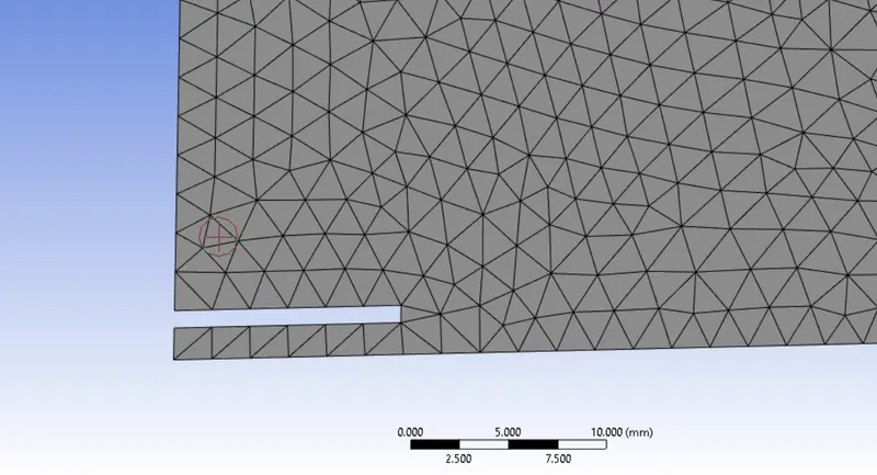
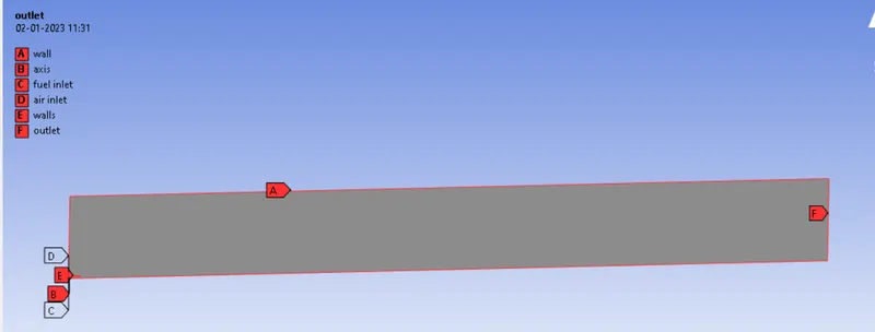
As the geometry is 2D in nature, the number of element required as compared to 3D model will be less. The mesh should be fine enough to caught every details of species and their reaction inside the chamber. The type of element which is used for meshing is Quad 4. Because of simplicity of geometry and accuracy of solution required, it is best practice to go with quadrilateral elements. The method used for the meshing is Automatic method in which Quadrilateral dominant method has been used. In the geometry there are some irregularity which cause element to reshape in zone of vicinity. The proximity size function is used for providing element in the smaller zones of geometry. The proximity size function requires number cell across the gap in geometry. As there is only one possible gap in geometry near the left hand bottom side and it is necessary to create more number of element near the fuel inlet. The number of cell in the gap is provided as 3 and the element size of 1.6mm is used for whole geometry.
FLUENT SETUP:-
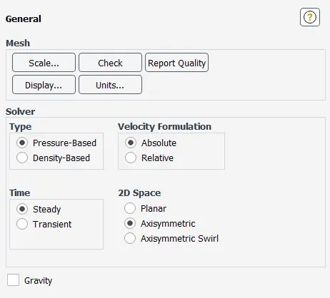
FLUENT setup and solving the required problem is the part of pre-processing. In this section the different part of setup is discussed in which viscous model setup, boundary conditions and solution method setup are involved. The general setup required for simulation is pressure based steady state approach for problem. The gravity is not enabled for the simulation. Figure 12 shows the general setup of FLUENT.
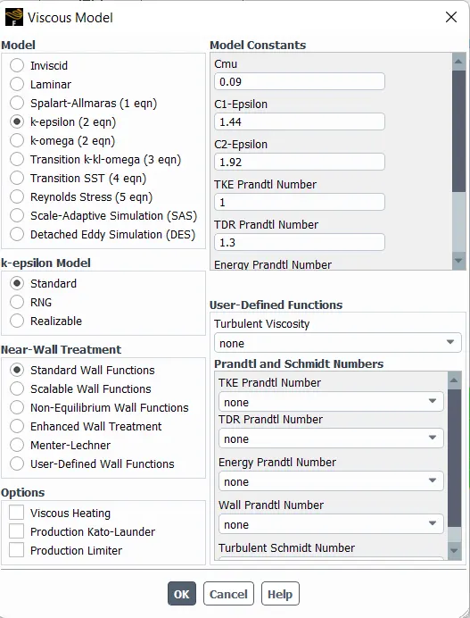
Viscous Model Setup:-
Species Model Setup:-
Species Model parameter for Simulation:-
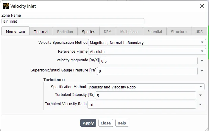
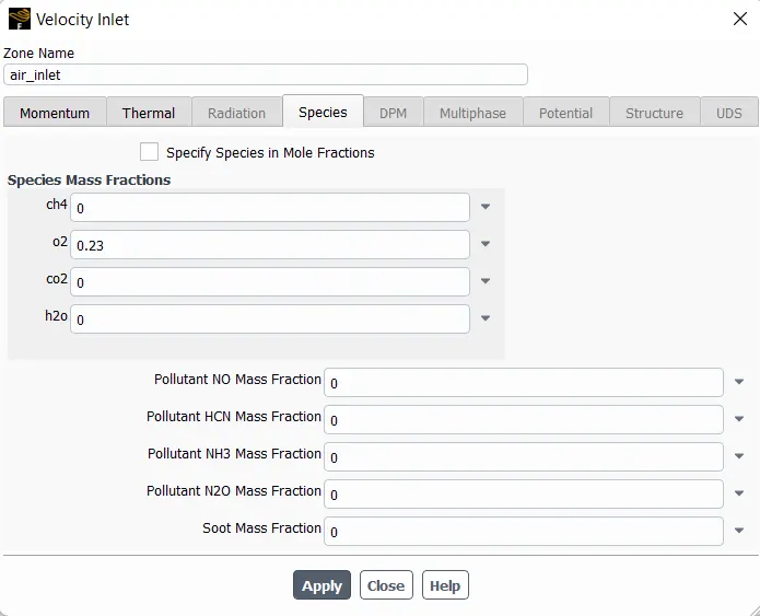
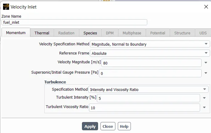
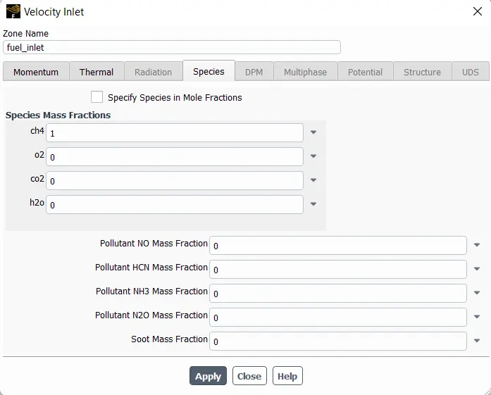
Specification of Boundary Condition:-
Solution Method
Solution method for the simulation is consider as default by FLUENT. Depend upon the version used FLUENT set the solution method as default. As it was found that version from 20 onward the default method of solution method is set as Coupled rather than SIMPLE in previous version. The spatial discretization for all species should be set as second order upwind function. For turbulent Kinetic energy and turbulent dissipation rate same second order upwind function has to be used for better convergence. The convergence factor is also set as default and hybrid initialization method is used to determine the initial value for calculation of whole simulation.
Baseline Mesh Result:-
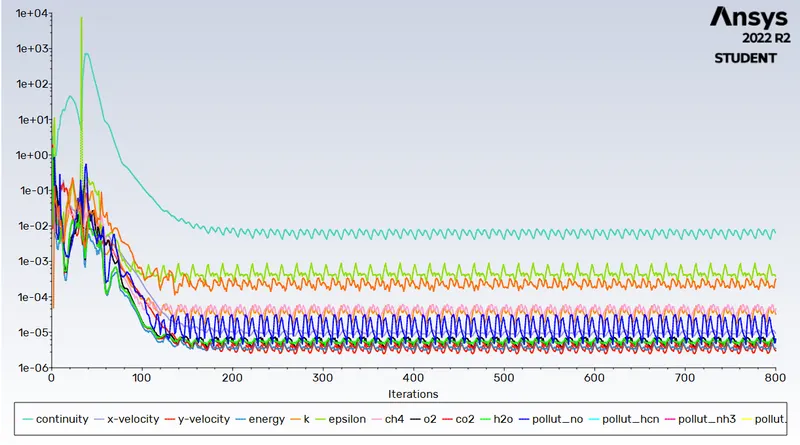
Residual Plot
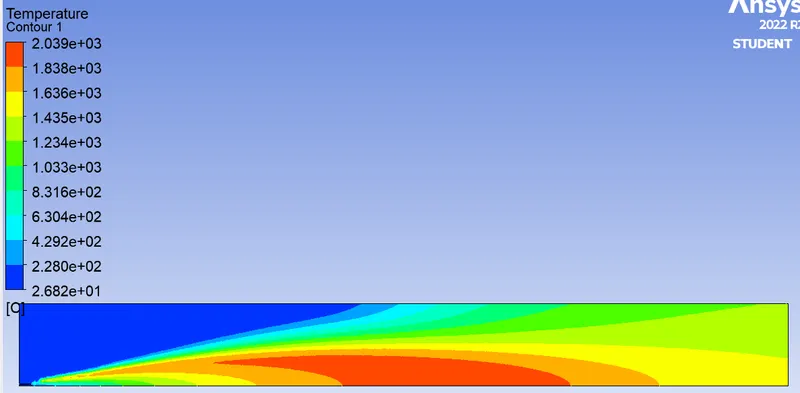
Temperature plot
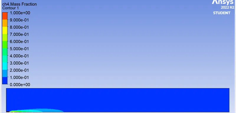
Mass fraction of CH4
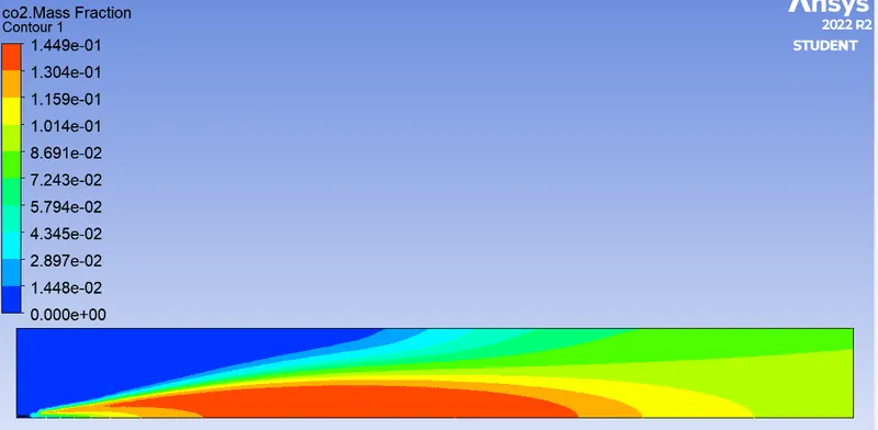
Mass Fraction of CO2
Mass Fraction of H2O
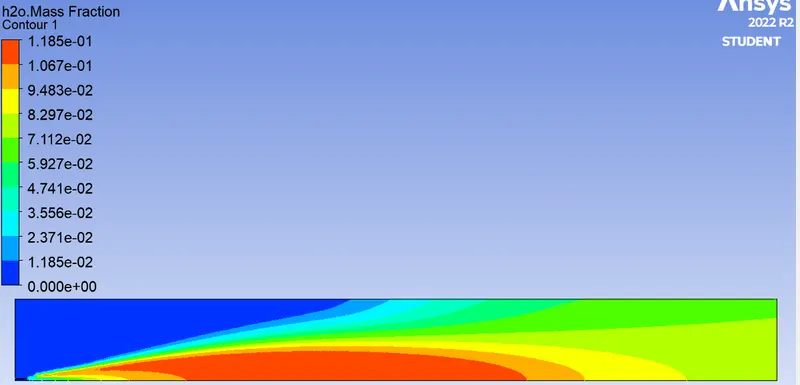
Mass Fraction of N2
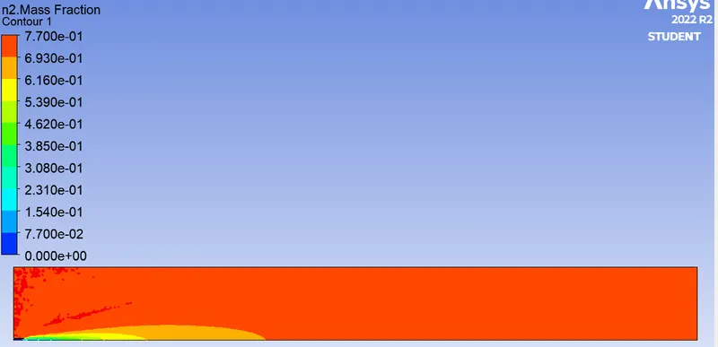
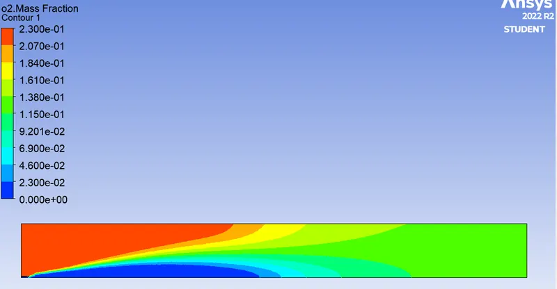
Mass Fraction of O2
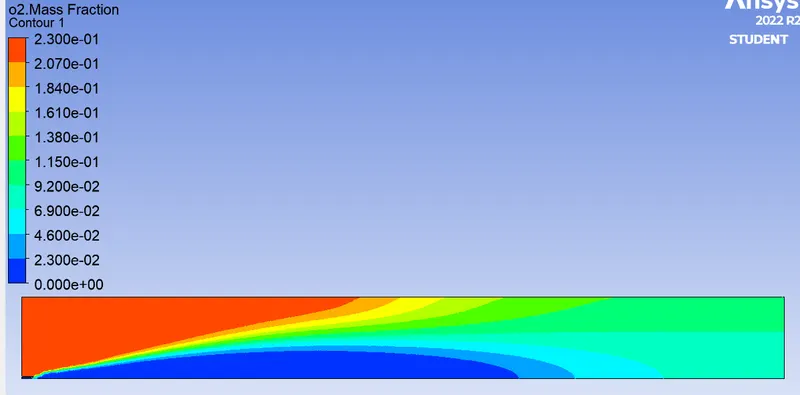
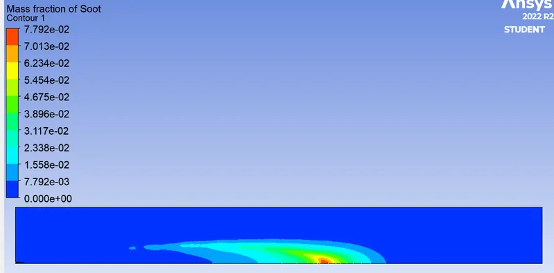
Mass Fraction of Soot
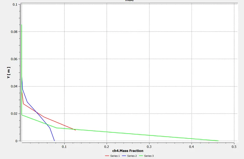
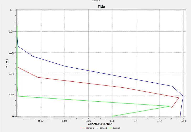
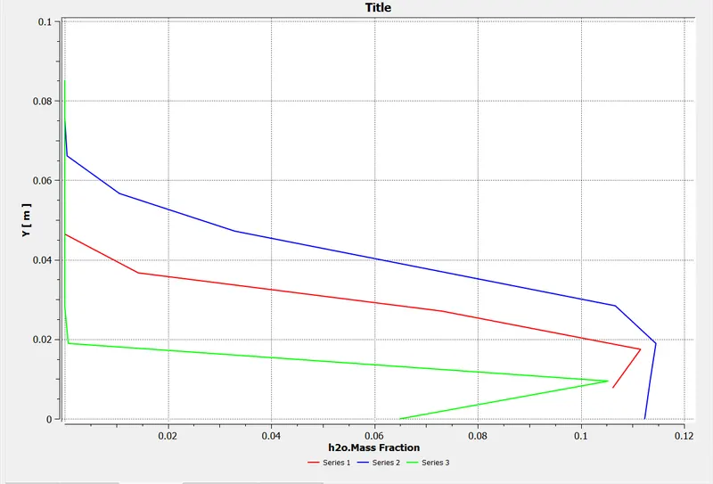
Line Plots for graphs
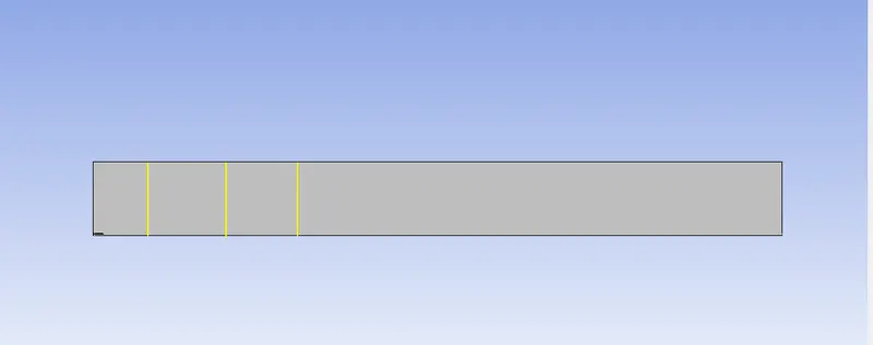
Graph of CH4
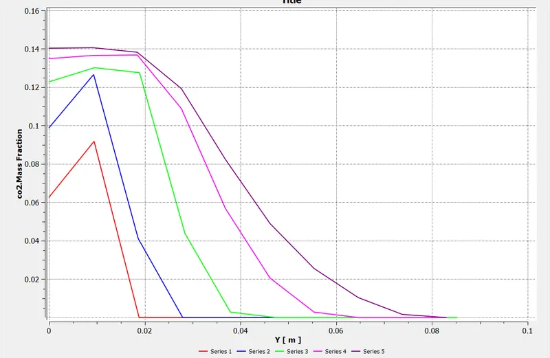
Graph of CO2
Graph of H2O
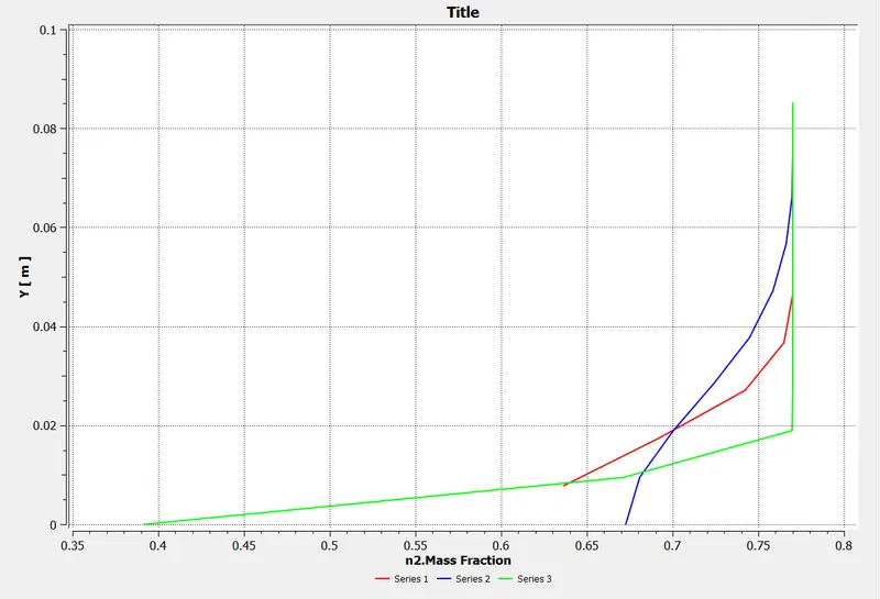
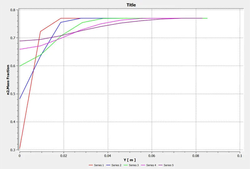
Graph of N2
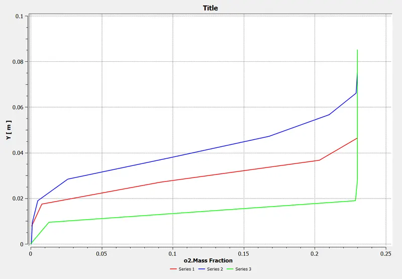
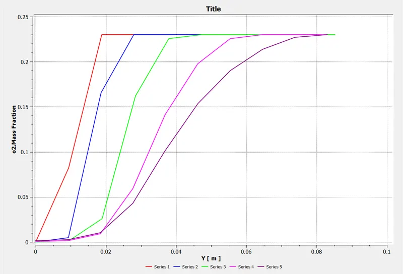
Graph of O2
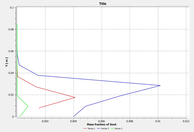
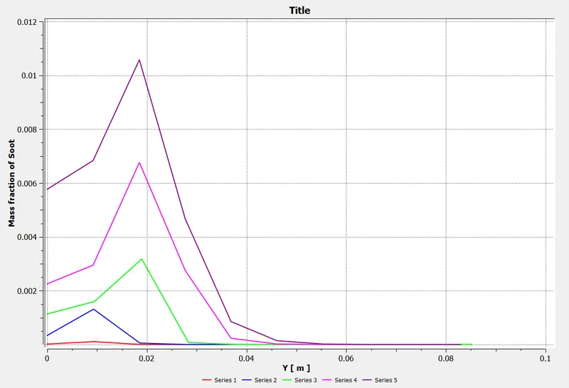
Graph of Soot
Case 1 - Oxygen 5%
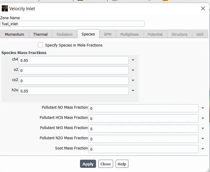
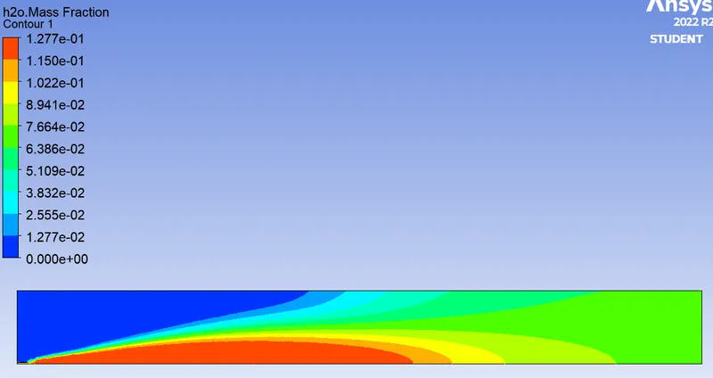
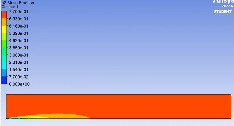
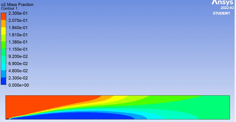
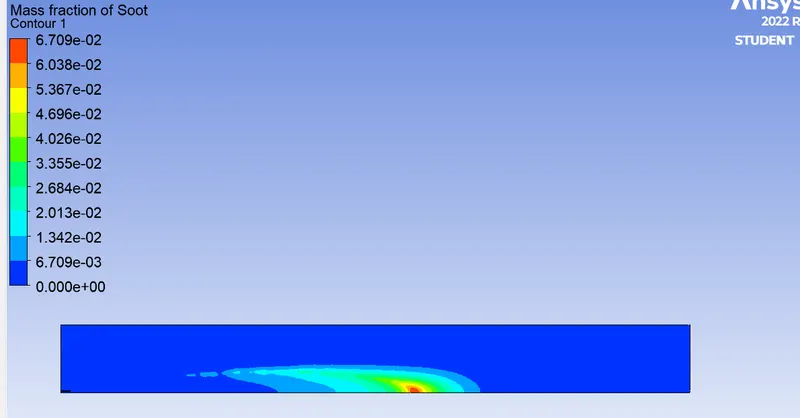
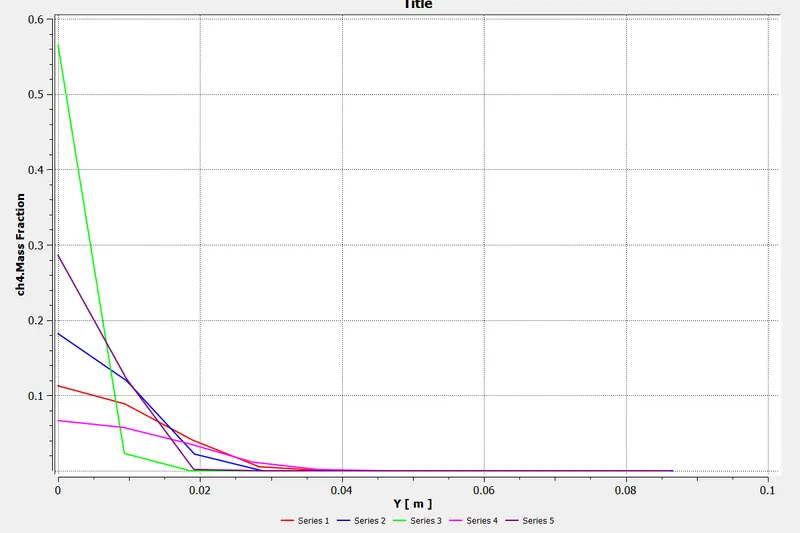
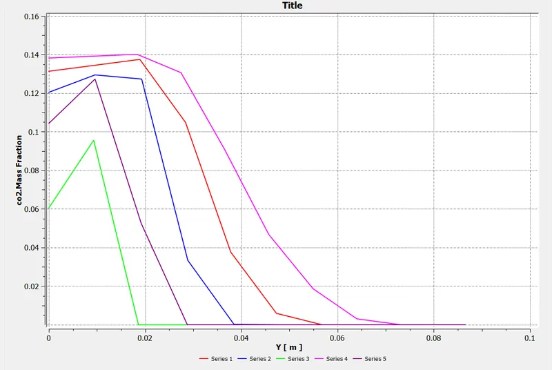
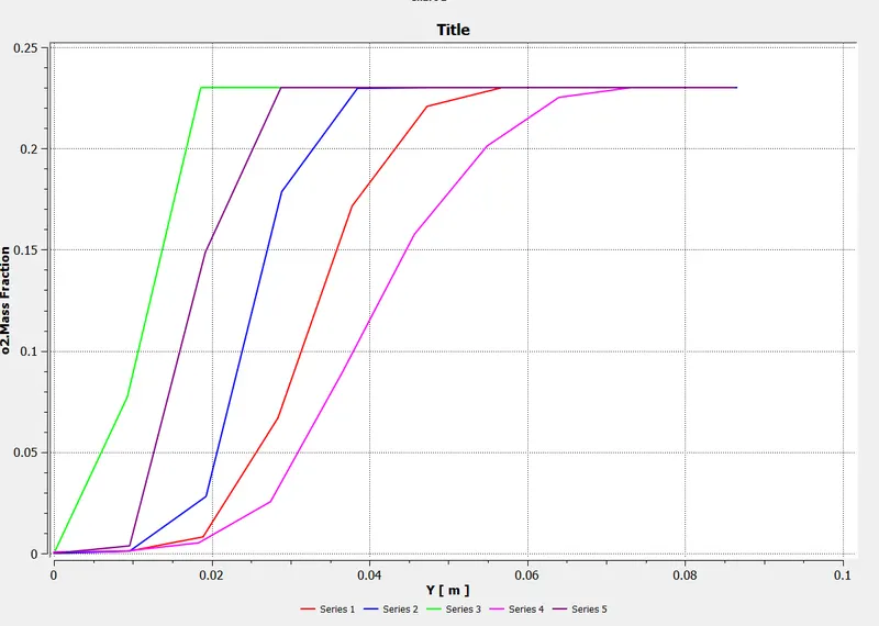
In baseline mesh setup it can be seen that there is proportion of NOx and soot is generated inside the burner. the location of NOx is toward the outlet is more and soot formation is done near the air inlet. To lower the NOx and soot formation in burner the fuel is mixed with Water vapour which entering from same inlet location. For this case only 5% of water is made to mix with fuel and flow at 80m/sec velocity. As the Mass fraction of water is increased in fuel inlet consequently the mass fraction of fuel has to be decrease. The mass fraction of water in this case will be 0.05 whereas mass fraction of fuel will be 0.95.
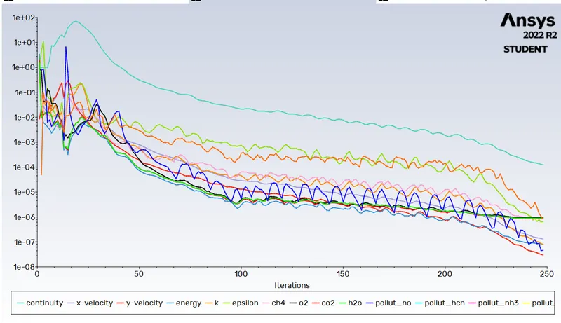
Residuals:-
Temperature plot:-
Mass Fraction of CH4
Mass Fraction of CO2
Mass Fraction of H2O
Mass Fraction of N2
Mass Fraction of O2
Mass Fraction of Soot
Graph of CH4
Graph of CO2
Graph of H2O
Graph of N2
Graph of O2
Graph of Soot
Case 2 - Oxygen 10%
In Case 2 the percentage of oxygen is increased by 5% again. The specification of mass fraction of fuel and water
Residuals:-
Temperature plot:-
Mass Fraction of CH4
Mass Fraction of CO2
Mass Fraction of H2O
Mass Fraction of N2
Mass Fraction of O2
Mass Fraction of Soot
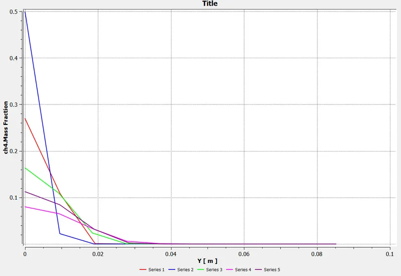
Graph of CH4
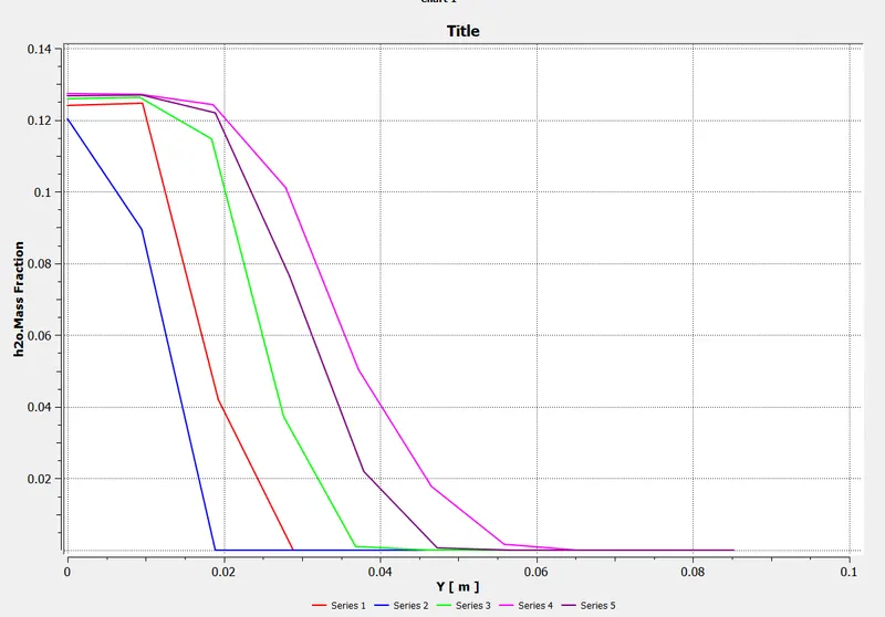
Graph of H2O
.
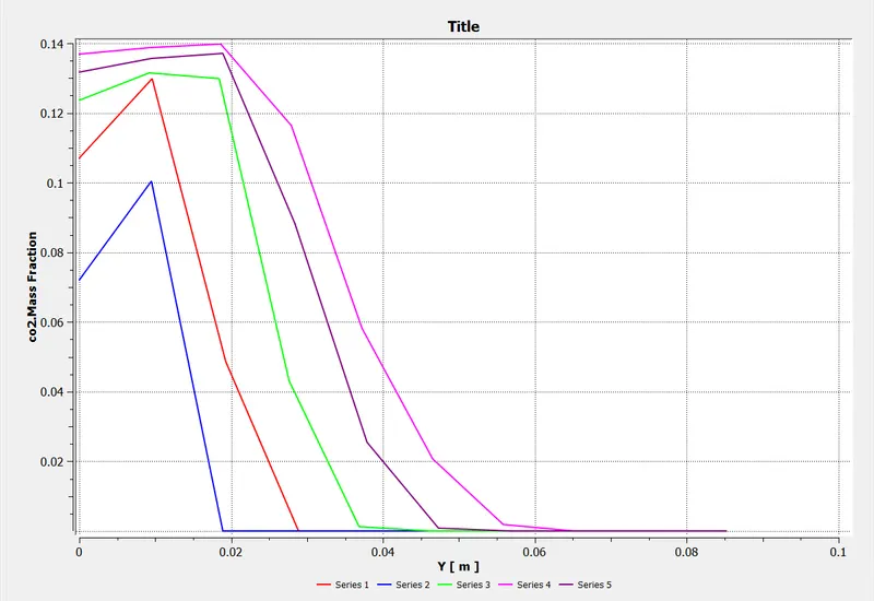
Graph of CO2
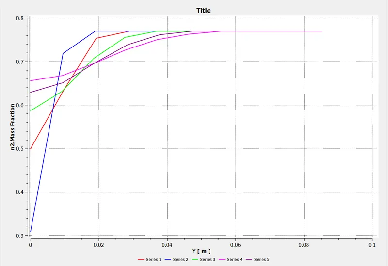
Graph of N2
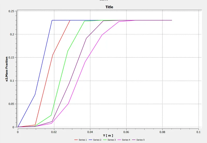
Graph of O2
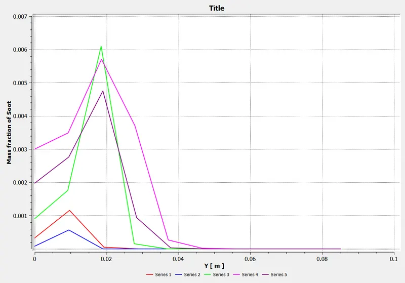
Graph of Soot
Case 3 - Oxygen 20%
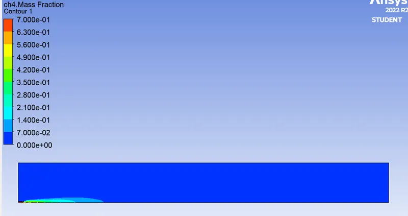
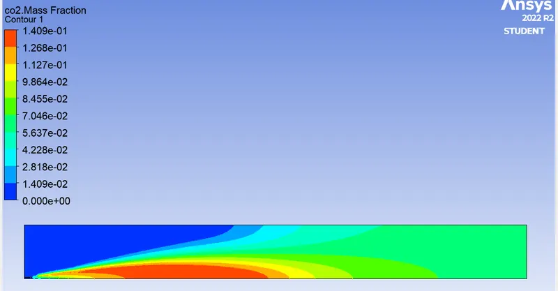
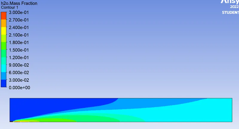
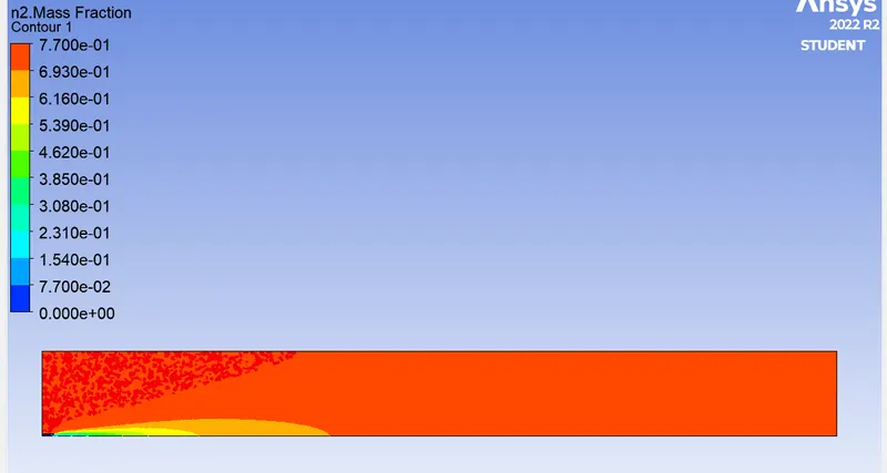
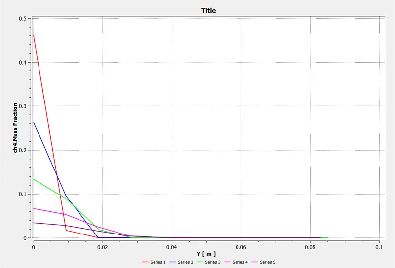
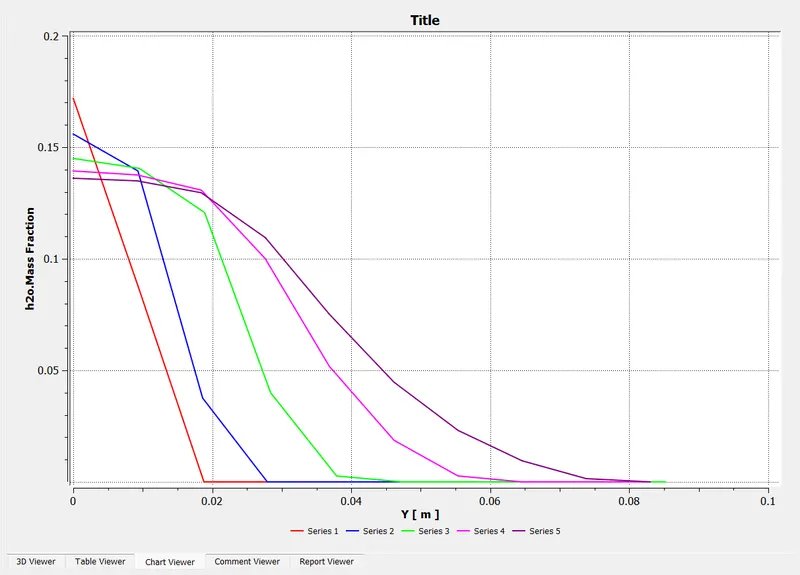
In Case 3 the percentage of oxygen is increased by 10% again. The specification of mass fraction of fuel and water
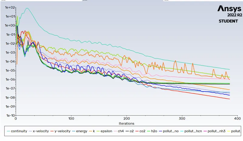
Residuals:-
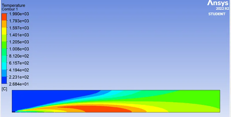
Temperature plot:-
Mass Fraction of CH4
Mass Fraction of CO2
Mass Fraction of H2O
Mass Fraction of N2
Mass Fraction of O2
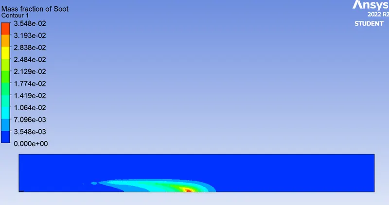
Mass Fraction of Soot
Graph of CH4
Graph of H2O
Graph of CO2
Graph of N2
Graph of O2
Graph of soot
Case 4 - Oxygen 30%
In Case 4 the percentage of oxygen is increased by 10% again. The specification of mass fraction of fuel and water
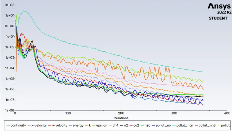
Residuals:-
Temperature plot:-
Mass Fraction of CH4
Mass Fraction of CO2
Mass Fraction of H2O
Mass Fraction of N2
Mass Fraction of O2
Mass Fraction of Soot
Graph of CH4
Graph of H2O
Graph of CO2
Graph of N2
Graph of O2
Graph of soot
Conclusion :-
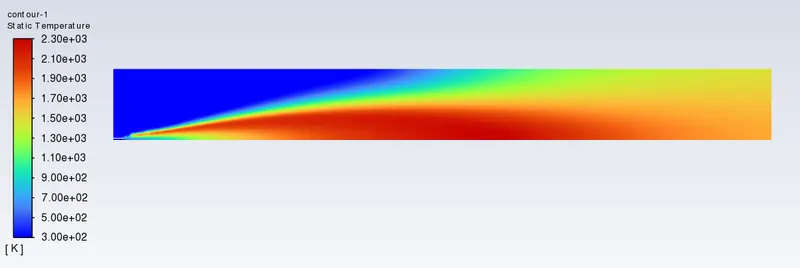
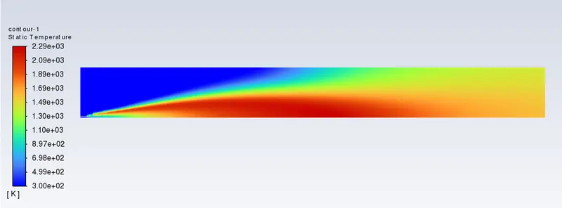
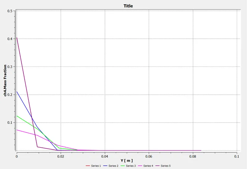
- In baseline mesh setup in which the whole amount of CH4 is present for as the fuel the amount of soot and NOx is greater as compared to other cases. Also the maximum temperature is about 2300 K.
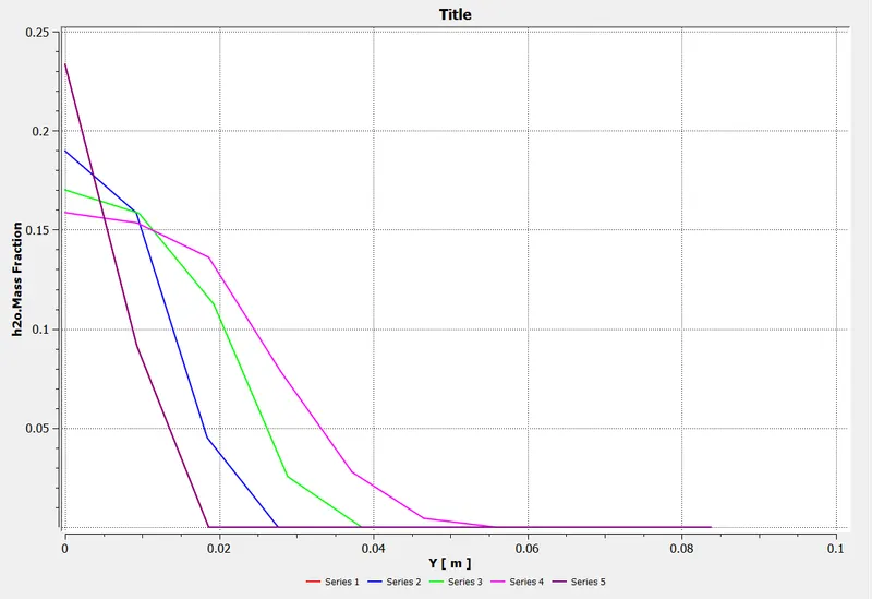
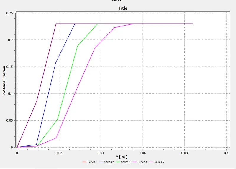
- In next cases where the water is added with fuel in respect of 5% to 30% there is reduction of NOx by certain amount. For case 1 the reduction of NOx is about 15.78%. For case 2 same reduction of NOx is 28.94%. For case 3 the NOx reduction is 52.64% whereas for case 4 the NOx reduction is about 71.05%. Hence adding the water with fuel is considerably decreasing the NOx emissions from the exhaust products.
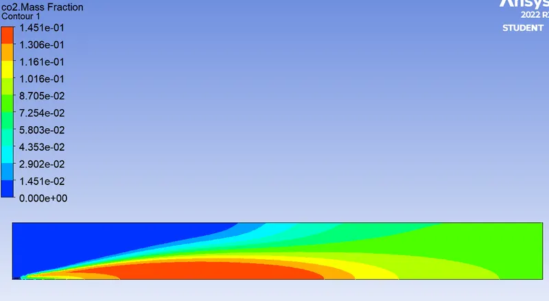
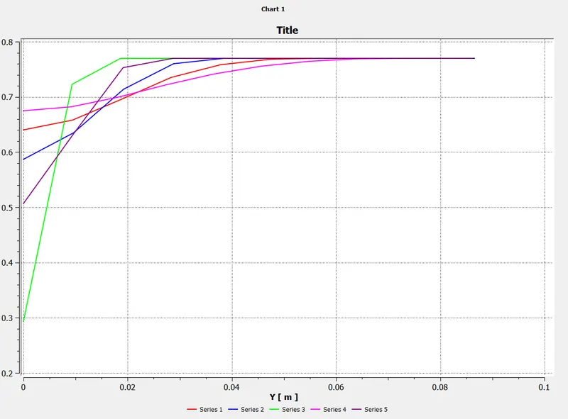
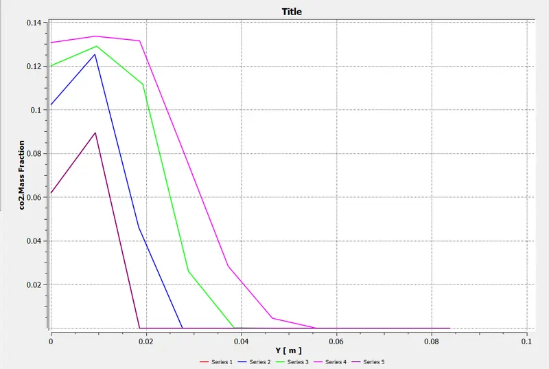
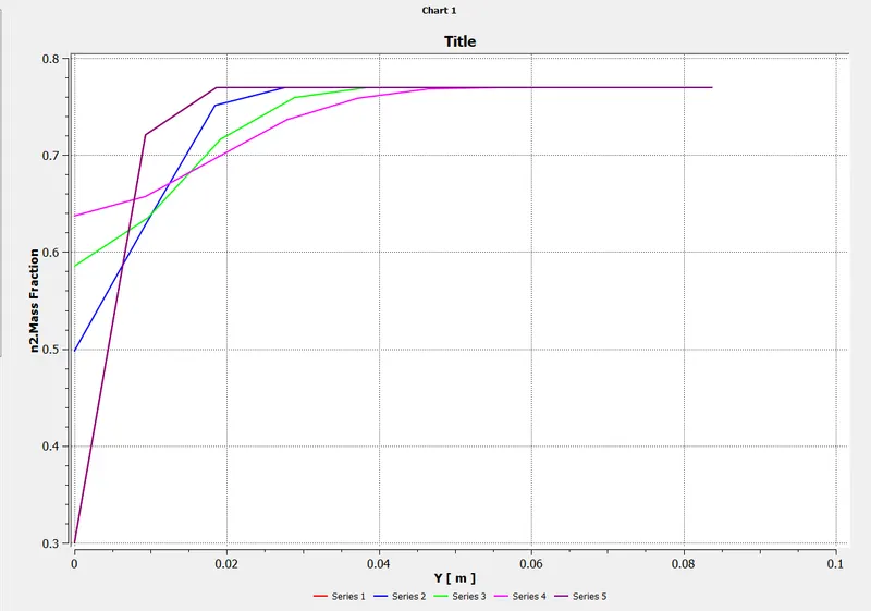
- Similar to NOx, from the result table it can be seen that the mass fraction of CO2 is also decreasing as water percentage is increasing. The Mass fraction of N2 is almost constant for all the cases which means the flame instability for the burner is almost constant for all the cases of combustion.
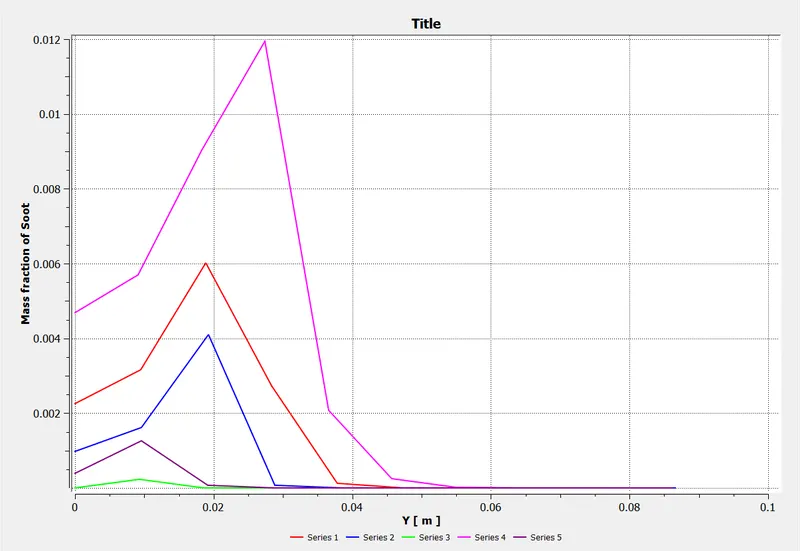
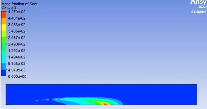
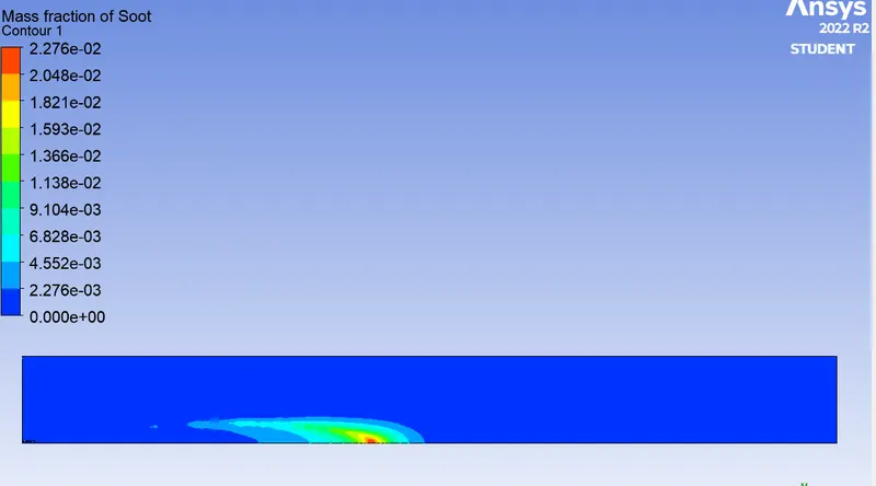
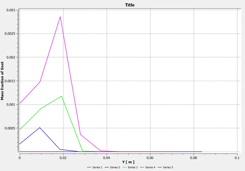
- In case of soot formation, it can see that, mass fraction of soot is decreasing for case 1 and 2 but for case 3 and 4 it has increased. After checking the Mass fraction of soot contour for all the cases, it is evident that soot formation from case 1 to 4 is unbalanced but the amount of soot formation is significantly lowered for case 3 and 4. It is seen that from case 3 and 4 contour of mass fraction of soot, the formation of soot is nearer toward the outlet of burner which is common practice of soot to deposited at the outlet.
- From the whole simulation it concluded that providing water with fuel will reduce the harmful exhaust emission such as NOx and Soot.