Week 10 - Simulating Combustion of Natural Gas.
AIM: To perform the heat transfer analysis using ansys fluent software foe the cylinderical lithium ion battery with heat generated boundary condition. the inlet air temperature of the encloser is as 26 C.
INTRODUCTION:
Battery modules store electricity required to drive the load on the system The power capacity of the battery is measure in KW.
the Battery thermal management system is (BTMS) to control the over heating of the battery.The high battery temperature leads to poor performance, short lifetime and risk of basting.the temperatureb should be maintain in optimum temperature range and keep uniform temperature.
THEORY:
Differenrt battery cooling methods used in BTMS. they are
1.AIR COOLING:
Air is easily available for cooling purposes and it is widely used in many industries. the air is not an effective coolant because of its lower heat capacity and low thermal conductivity. the cooling is possible either by forced convection mode and natural convection mode. Natural convection cooling is suitable for low density batteries and typically blowers or fans can be used to enhance the convection heat transfer rate.
2.Liquid cooling of battery:
Liquid cooling have a high convective heat removal rate due to higher density and heat capacity compared to air. A liquid cooling system is more compact than an air system. We can save up to 40% of separate power compared to the fans required for air cooling. there two types of liquid cooling
indirect liquid cooling:
Water has been an effective coolant for several industrial applications But the main challenge is the short-circuited potential for direct cooling of batteries.To avoid the short-circuit issue, indirect methods are effective to avoid electrical conduction with cells while maintaining high thermal diffusion. The addition of electrical resistance may resist thermal diffusion. But its effects on cooling is not significant. Some EV manufacturers such as General Motors, and Tesla are using indirect cooling in their cars. General Motor used cold plates between each prismatic cell. The cold plates have several micro-channels for convective heat removal from batteries.
direct liquid cooling:
Direct cooling is also called immersion cooling, covers the entire surface of the cell and cools it uniformly. Immersion cooling removes hot or cold spots in the cell and significantly improves the performance of the cell. Ideal coolant mush be dielectric with minimum viscosity and high thermal conductivity and thermal capacity. Immersion cooling is widely used for data center servers and high-power electronics devices. BTMS for this method is not suitable for most mass-produced EV due to high cost and safety concerns
SLOVING AND MODELLING APPROACH:
1. First i open the workbench and then i drag the anasys fluent into the work space. then i open then geometry on the popup and i open the spaceclaim.
2. then in made cylinder shape of of a single battery.
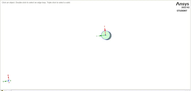
fig: single battery.
3.then i made the single cylinder to the 4*2 battery.
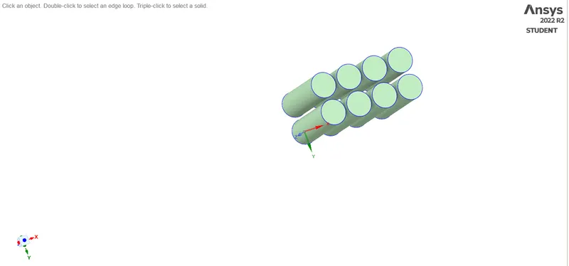
fig: 4*2 battery.
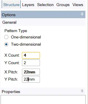
fig: pattern making setup.
4.then i made encloser on the 15 and 18 space sides, bottom and top between the cylinders and the encloser of the battery. then i made share topology to make the
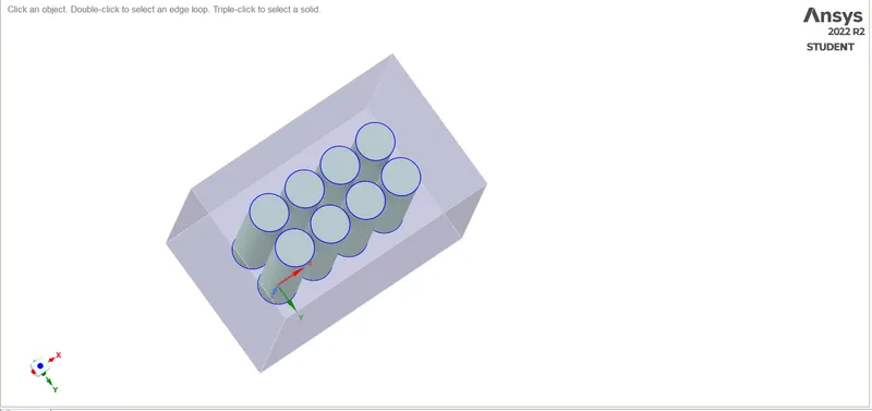
fig: battery with encloser.
5. then i open the meshing part to make mesh on the geometry with defualt mesh size. then i have given the name of the each and every part like inlet, outlet, convection wall,battery and fluidb domain.
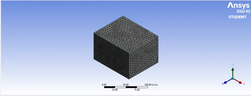
fig: geometry with meshed.
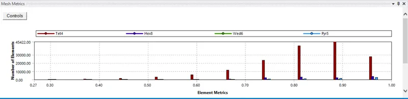
fig: mesh quality.
6.And i have done the mesh independed study on the case 6 and case 7. with mesh size of 6mm and 4mm.
fig: case 6 meshed geometry.
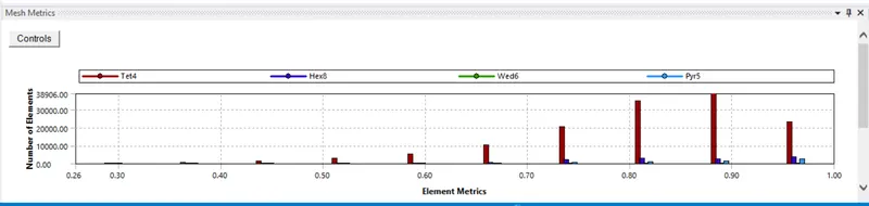
fig: case 6 mesh quality.
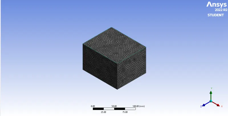
fig: case 7 meshed geometry.
fig:case 7 mesh quality.
7.then i went to the setup of the simulation part to give the inlet air velocity, turn on enegry equation, then i given the viscous model of k-omega SST model and the i have given the material for the geometrty parts like lithium and alumnium. then im went to material in the data based fluent in the i ahave selected the lithum and the alumnium.
8.then i went to the cell zone to set the battery material has a lithium with the heat source enable and given the 1 heat source and i given the constant 48750W/m^3.
9.then i have given the report for max temperature, avg temperature and HTC report by selecting the option called definitions in the surfrace report in the i selected according to the requirment. and i created the parameter outputs.
10. then made the contoue plots of velocity and temperature and then made a animation by selecting the auto saving the animation for the velocity contour.
11.here the setup and solution process is same for all the cases but the the velocity of the inlet Air is varing by 3m/s, 5m/s and 10m/s.
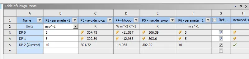
fig: parameteric study.
OUTPUT:
case 1 the space betwwen the batteris 2mm velocity is 3m/s.
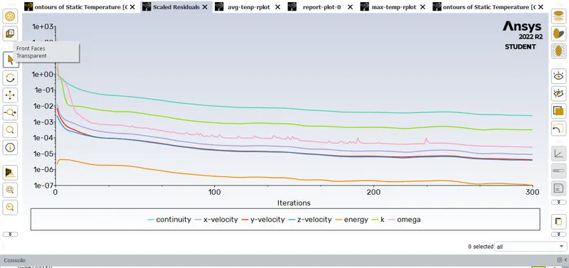
fig: residual plot.
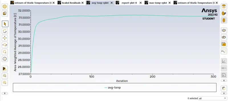
fig: Avg temperature plot.
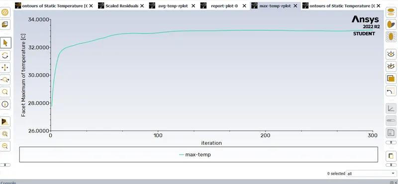
fig:Max temperature plot.
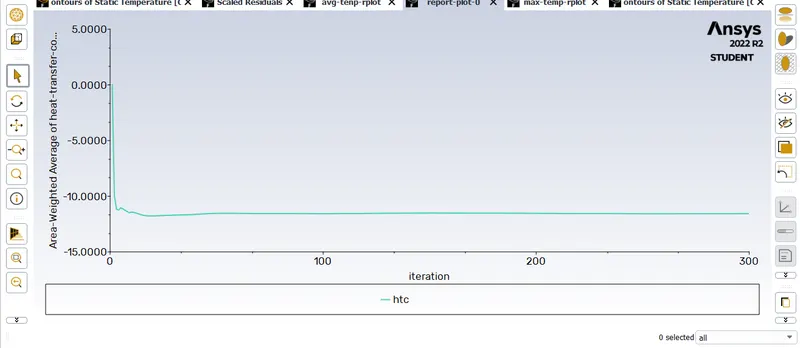
fig: HTC plot.
case 2 the space betwwen the batteris 2mm velocity is 5m/s.

fig: residual plot.
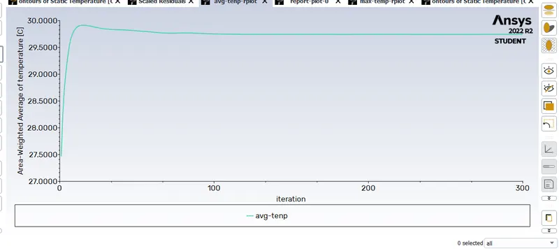
fig: avg temperature plot.
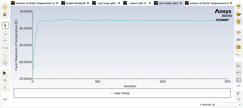
fig: Max temperature plot.
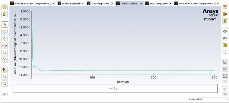
fig:Htc plot.
case 3 the space betwwen the batteris 2mm velocity is 10m/s.
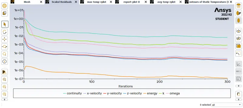
fig: residual plot.
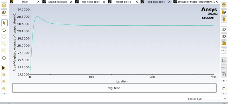
fig:Avg temperature plot.
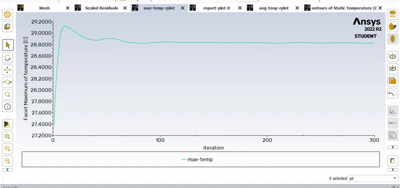
fig: Max temperature plot.
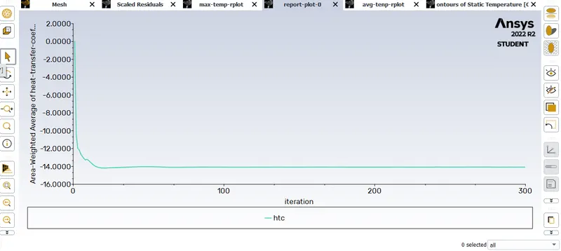
fig: Htc plot
case 4 the space betwwen the batteris 4mm velocity is 5m/s.

fig:residual plot
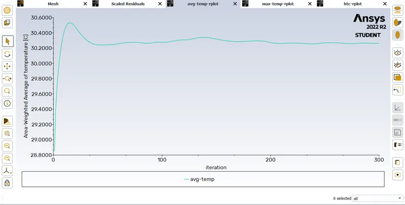
fig: Avg temperature plot.
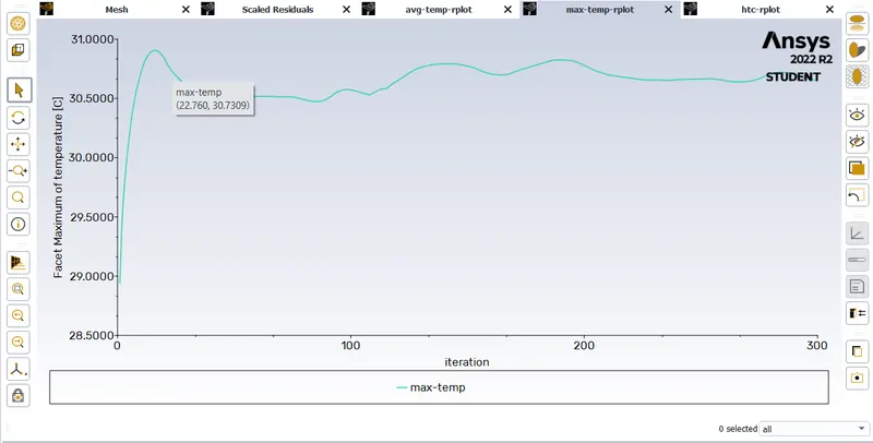
fig: Max temperature plot.
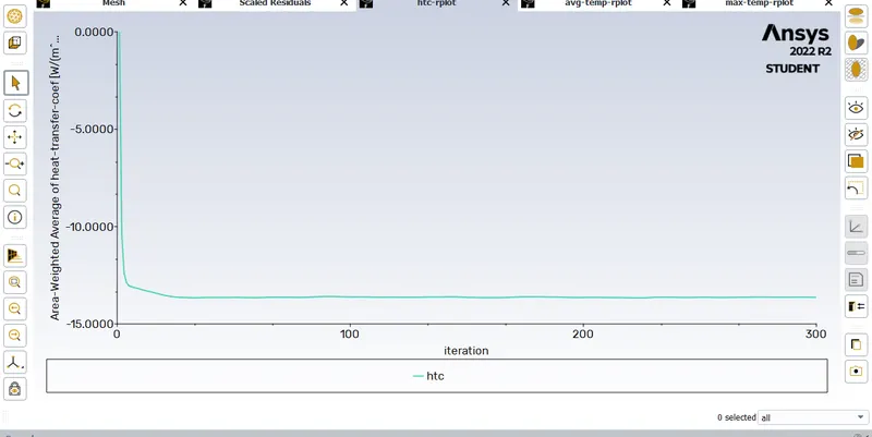
fig: Htc plot.
case 5 the space betwwen the batteris 6mm velocity is 10m/s.
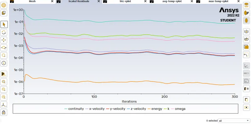
fig: residual plot.
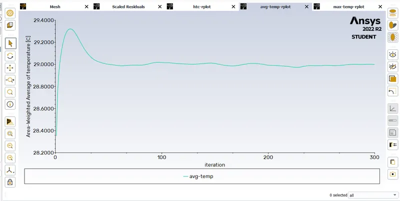
fig: Avg temperature plot.
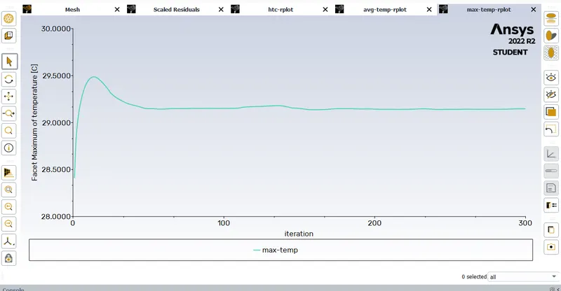
fig: Max temperature plot.
fig: Htc plot.
case 6 the space betwwen the batteris 2mm velocity is 5m/s, and mesh size 6mm.
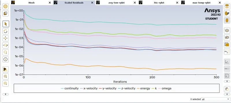
fig: residual plot.
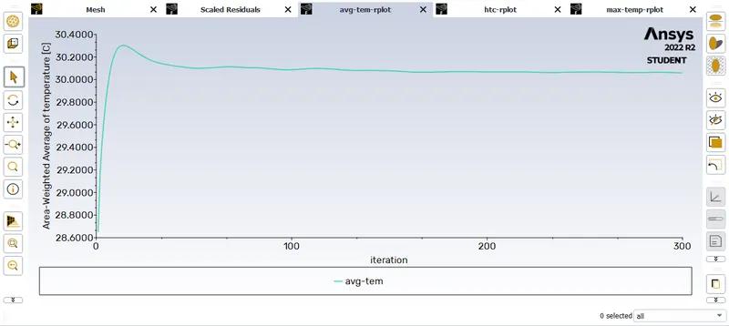
fig: Avg temperature plot.
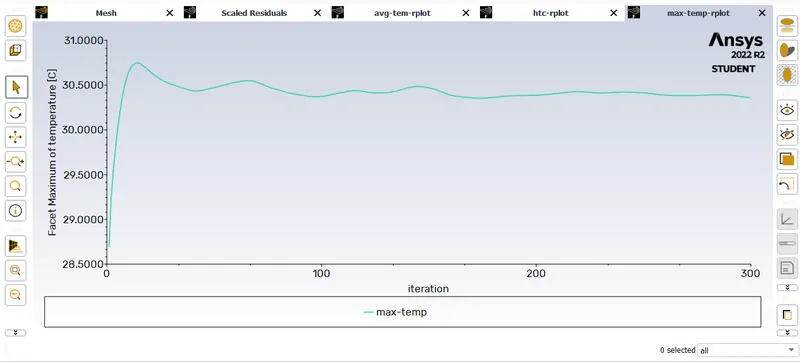
fig: Max temperature plot.
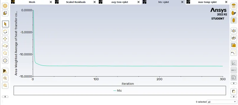
fig: Htc plot.
case 7 the space betwwen the batteris 2mm velocity is 5m/s, and mesh size 4mm.
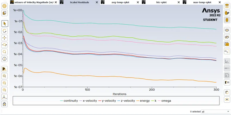
fig: residual plot.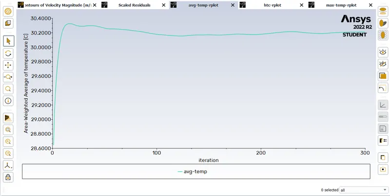
fig: Avg temperature plot.
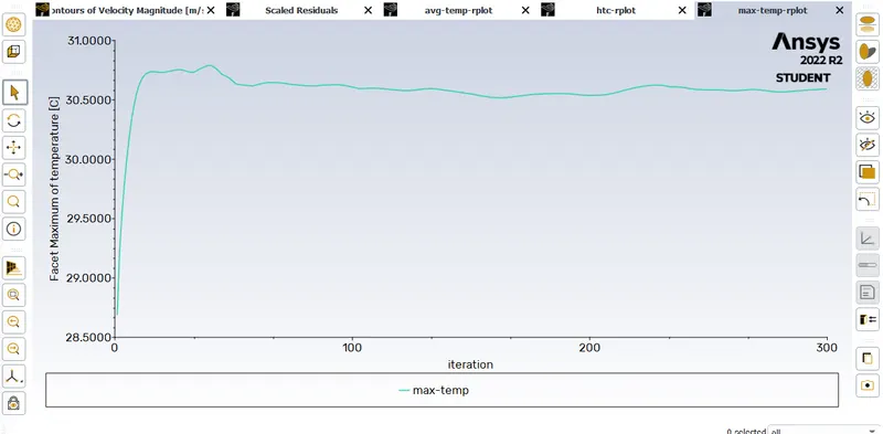
fig: Max temperature plot.
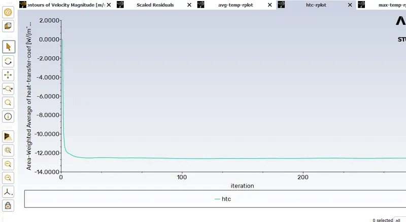
fig: HTC plot.
RESULT:
CASE 1
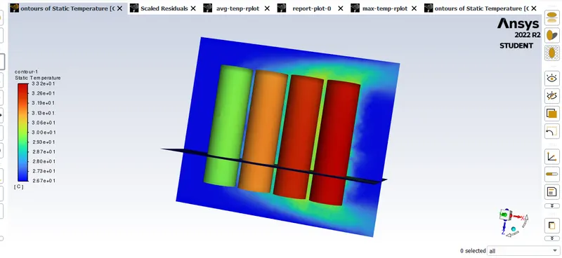
fig: temperature contour.
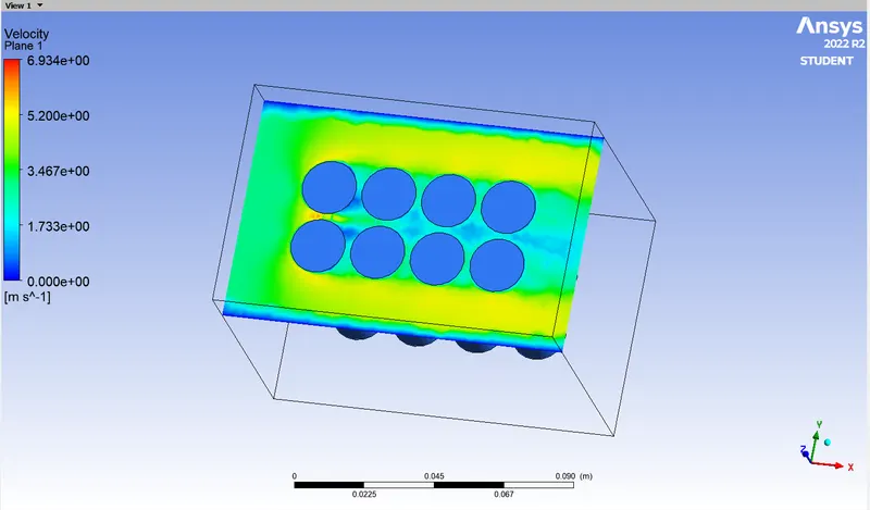
fig: velocity contour.
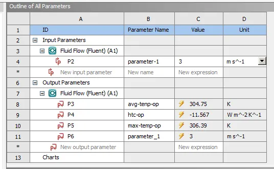
fig: parameter outline.
CASE 2
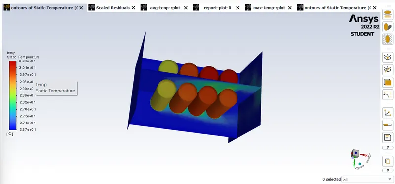
fig: temperature contour.
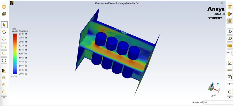
fig: velocity contour.
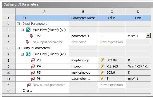
fig: parameter outline.
CASE 3
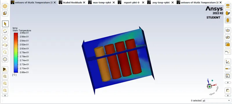
fig: temperature contour.
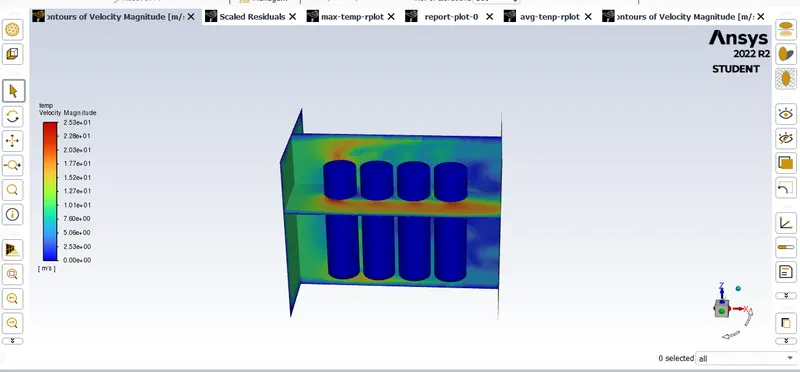
fig: velocity contour.
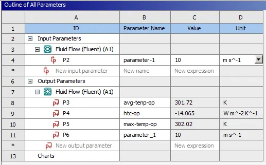
fig: parameter outline.
CASE 4
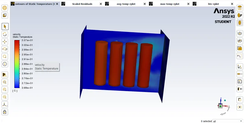
fig: temperature contour
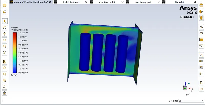
fig: velocity contur
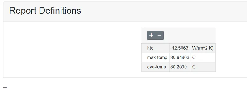
fig: parameter output.
CASE 5
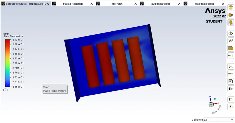
fig: temperature contour
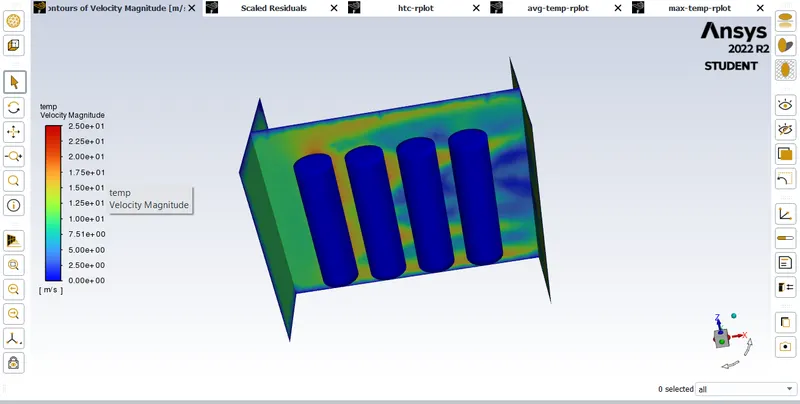
fig: velocity contour.

fig: parameter output.
CASE 6
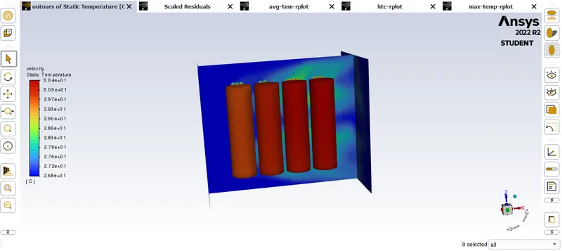
fig: temperature contour
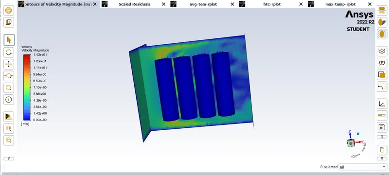
fig: velocity contour
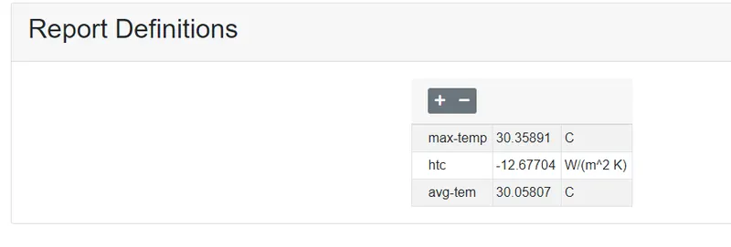
fig: parameter output.
CASE 7
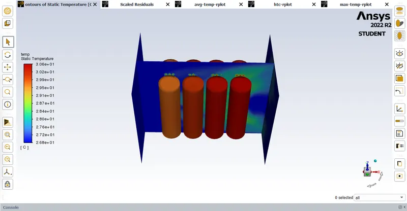
fig: temperature contour
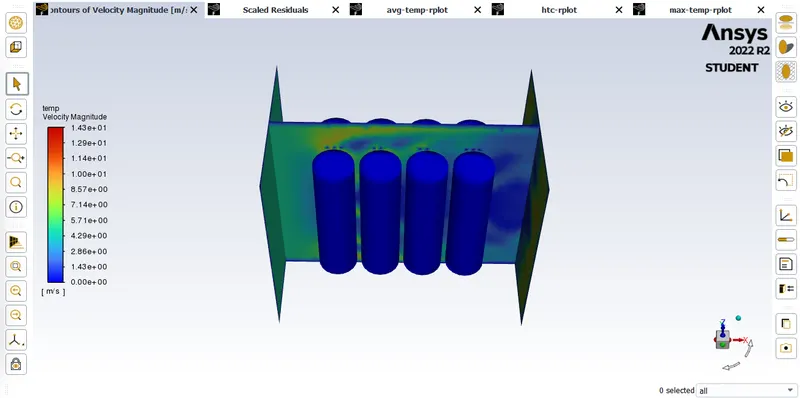
fig: velocity contour.
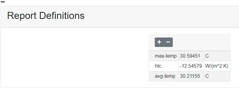
fig: parameter output.
CONCLUSION:
here i conclude that the when the air velocity is increases the heat transfer coefficient also increases, the max and avg temperature of the batteries will decreases, the space between the batteries is increases the the heat transfer coefficent also increases and the max and avg temperature of the batteries will decreases.but in case one the first batteries only cooled and remain batteries are some word more temperature then the front batteries. to maintain the constant tempeture across the proper gap should be maintain between the batteries. case 6 is the better one to cool the batteries that with gap betwwen the batteries is 6mm and the inlet air velocity is 10m/s so the heat transfer is more and the over temperature is low compared to all the other casess.
ANIMATION LINK
https://drive.google.com/file/d/1BveRX917b2kOSlQJJTITGQufoTuqvxow/view?usp=sharing