Simulating Combustion of Natural Gas.
Aim: To perform a combustion simulation on a combustor model using Methane as fuel.
Objectives
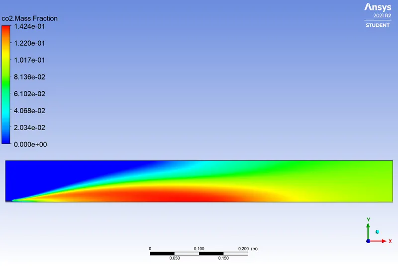
This project comprises two main parts with. In the first part, the objective is to calculate the mass fraction of different species such as CO2, H2O, CH4, N2, O2 and determine NOx emissions and Soot formation.
In the second part, the objective is to add water content to fuel and observe the resulting effects. Apart from the two main objectives, this project allows us to learn how to set a combustion model and run its simulation for a specific purpose.
Introduction
Combustion is a high-temperature exothermic redox chemical reaction between a fuel that is the reductant and an oxidant usually atmospheric oxygen that produces oxidized often gaseous products in a mixture termed as smoke. It is notable that, combustion does not always result in fire; since a flame is only visible when substances undergoing combustion vaporize but when it does, flame is a characteristic indicator of the reaction. In this project, a combustion simulation is carried out on a combustor model using ANSYS Fluent. The mole and mass fractions ok different species are computed and NOx emissions as well as Soot formation are determined.
Theory
As defined above, combustion is often a complicated sequence of elementary radical reactions. Combustion is often hot enough that incandescent light in the form of either glowing or a flame is produced. A simple example can be seen in the combustion of hydrogen and oxygen into water vapor, a reaction commonly used to fuel rocket engines. This reaction releases 242 KJ/mol of heat and reduces the enthalpy accordingly (at constant temperature and pressure).
The equation of such reaction is as follows:
`2H_2 (g)+O_2 (g)→2H_2 O(g)`
Generally, the stoichiometric combustion of a hydrocarbon in oxygen is given by the following chemical equation:
`C_x H_y+zO_2→xCO_2+ y/2 H_2 O`
In the above equation, z=(x+y)/4
In order to properly understand combustion process, it is convenable to dive into some specific terms involved:
- Chemical kinetics
Chemical kinetics also known as rection kinetics is the branch of physical chemistry that deals with the understanding the rates of chemical reactions. It is to be contrasted with thermodynamics, which deals with the direction in which a process occurs but in itself tells nothing about its rates. Chemical Kinetics includes investigations of how experimental conditions influence the speed of a chemical reaction and yield information about the reaction’s mechanism and transition states as well as the construction of mathematical models that can describe the characteristics of a chemical reaction.
- Chemical reaction model
Chemical reaction models transform the physical knowledge into a mathematical formulation that can be utilized in computational simulation of practical problems in chemical engineering. Computer simulation provides the flexibility to study chemical processes under a wide range of conditions. Modelling a chemical reaction involves solving the conservation equations describing convection, diffusion and reaction source for each component species.
The Species Transport Equation is given as follows:
`(∂(ρY_i))/(∂t)+∇*(ρv ⃗Y_i )=-∇*(J_i ) ⃗+R_i+S_i`
In the above equation, Ri is rate of production of species i by chemical reaction and Si is the rate of creation by addition from the dispersed phase and the user-defined source. Ji is the diffusion flux of species i, which arises due to concentration gradients and differs in both laminar and turbulent flows, computational fluid dynamics also considers the effects of turbulent diffusivity. The net source of chemical species i due to reaction, Ri which appeared as the source term in the species transport equation is computed as the sum of the reaction sources over the Nr reactions among the species.
Applications
The mathematical models that describe chemical reaction kinetics provide chemists and chemical engineers with tools to better understand and describe chemical processes such as food decomposition, microorganism growth, stratospheric ozone decomposition, and the chemistry of biological systems. These models can also be used in the design or modification of chemical reactors to optimize product yield, more efficiently separate products, and eliminate environmentally harmful by-products. When performing catalytic cracking of heavy hydrocarbons into gasoline and light gas, for example, kinetic models can be used to find the temperature and pressure at which the highest yield of heavy hydrocarbons into gasoline will occur.
Chemical Kinetics is frequently validated and explored through modelling in specialized packages as a function of ordinary differential equation-solving (ODE-solving) and curve-fitting.
- Mass fraction
A mass fraction can also be expressed, with a denominator of 100, as a percentage by mass. It is one way of expressing the composition of a mixture in a dimensionless size; mole fraction (percentage by moles, mol%) and volume fraction (percentage by volume, vol%) are others.
When the prevalence’s of interest are those of individual chemical elements, rather than of compounds or other substances, the term mass fraction can also refer to the ratio of the mass of an element to the total mass of a sample. In these contexts, an alternative term is a mass per cent composition. The mass fraction of an element in a compound can be calculated from the compound's empirical formula or its chemical formula.
- Nitrogen Oxide (NOx) emissions:
Nitrogen dioxide is an irritant gas, which at high concentrations causes inflammation of the airways. When nitrogen is released during fuel combustion it combines with oxygen atoms to create nitric oxide (NO). This further combines with oxygen to create nitrogen dioxide (NO2). Nitric oxide is not considered to be hazardous to health at typical ambient concentrations, but nitrogen dioxide can be. Nitrogen dioxide and nitric oxide are referred to together as oxides of nitrogen (NOx).
NOx gases react to form smog and acid rain as well as being central to the formation of fine particles (PM) and ground-level ozone, both of which are associated with adverse health effects.
- Soot formations:
Soot forms when hydrocarbon fuels such as oil, natural gas, and wood are burned. Soot particles form when gaseous molecules are heated to high temperatures, and they don't easily turn back into gaseous molecules the way water droplets do when they are heated. Soot as an airborne contaminant in the environment has many different sources, all of which are results of some form of pyrolysis. They include soot from coal-burning, internal-combustion engines, power-plant boilers, hog-fuel boilers, ship boilers, central steam-heat boilers, waste incineration, local field burning, house fires, forest fires, fireplaces, and furnaces. These exterior sources also contribute to the indoor environment sources such as smoking of plant matter, cooking, oil lamps, candles, quartz/halogen bulbs with settled dust, fireplaces, exhaust emissions from vehicles, and defective furnaces.
Moreover, while using ANSYS Fluent, there are limited types of combustion that can be run. Thus, the possible types of combustion simulation in ANSYS Fluent are listed below:
Combustion based on Mixing
- Non-Premixed Combustion
o In non-premixed combustion, fuel and oxidizer enter the reaction zone in distinct streams.
o It occurs during direct injection or late injection of fuel in IC engines. o Examples of non-premixed combustion includes pulverized coal furnaces, diesel internal-combustion engines and pool fires.
- Premixed Combustion
o in premixed combustion, fuel and oxidizer are mixed at the molecular level prior to ignition.
o Combustion occurs as flames front propagating into the unburnt reactants.
Examples of premixed combustion include aspirated internal combustion engines, lean- premixed gas
turbine combustors, and gas-leak explosions.
- Partially Premixed Combustion
o Partially premixed combustion systems are premixed flames with non-uniform fuel-oxidizer mixtures (equivalence ratios).
o Such flames include premixed jets discharging into an inert atmosphere, lean premixed combustors with diffusion pilot fames and cooling air jets, and imperfectly mixed inlets.
Combustion based on Phase
- Fluid Phase (Volumetric Reactions)
- Combustion takes place in the fluid region.
- Wall (Surface Reactions)
- Combustion takes on the wall or a solid surface.
- Particles (Surface Reactions)
- Combustion takes place on the Lagrangian particles.
- Combustion of coal is an example of particle combustion.
- Porous Region
- Combustion takes place in a porous region
- The reactions in an after-treatment system is an example of combustion in the porous regions
Modeling and Preprocessing
- Modeling
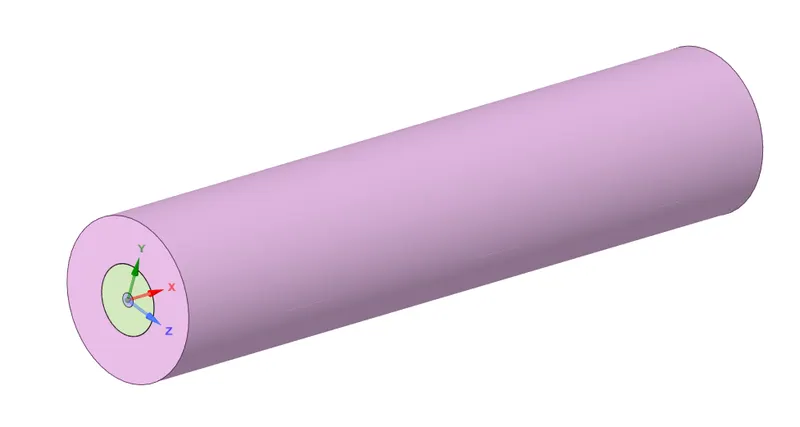
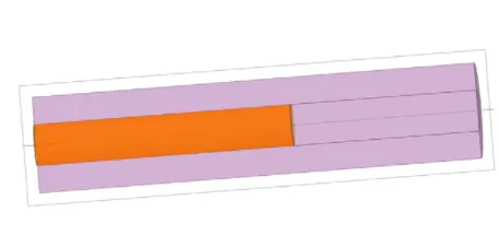
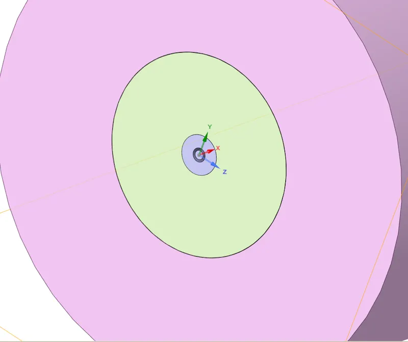
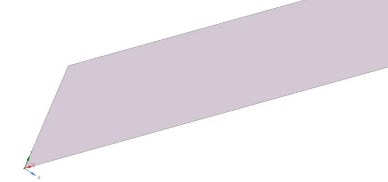
The geometry is imported in SpaceClaim. Since the simulation to be run is a 2D axisymmetric in nature, the imported 3D model is transformed into a 2D model as shown in the images below. This is done because simulating the 3D combustor is heavy and expensive since it will require more memory capabilities. The 2D geometry is obtained from 3D model using "split body" option.
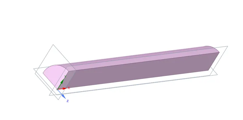

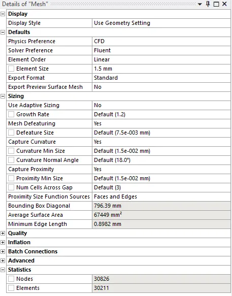
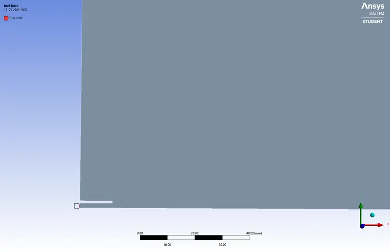
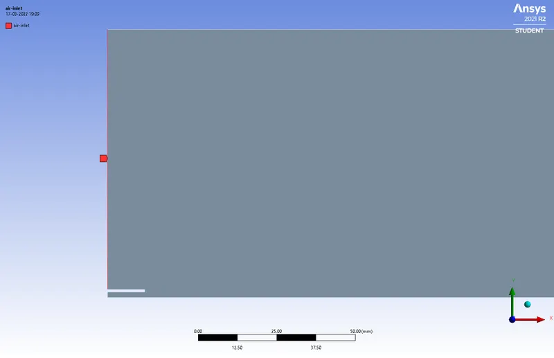
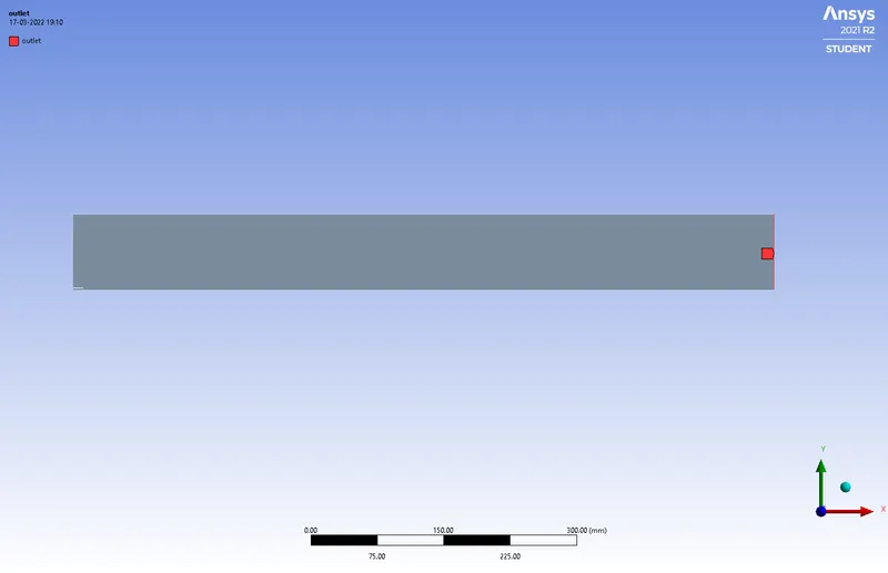
After that, the geometry is transferred to the mesh module for meshing. The meshing size is set as 1.5 mm. The capture proximity option is enabled and the Num Cells Across Gap is set to 3. Then, the named selection is defined where different parts of the geometry are as follows: fuel-inlet, air-inlet, outlet, axis, wall-side and walls. The case is then transferred to Fluent.

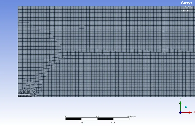
Fuel inlet Air-inlet
Outlet Wall
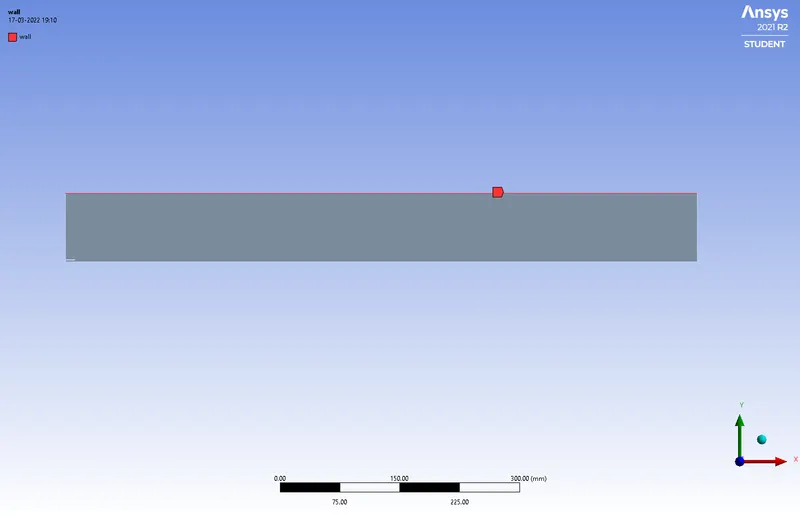
Axis
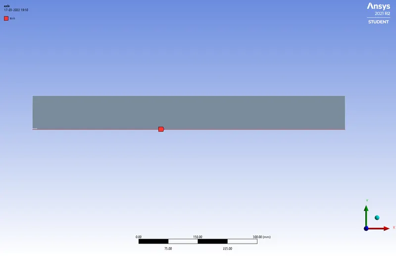
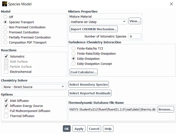
Once in Fluent, the Axisymmetric option is chosen and a steady-state simulation is set with Pressure-Based solver. The energy solver is enabled with viscous model set to k-Ꜫ model in order to obtain eddy dissipation model (which is a Chemistry interaction model). After that, the species option is opened and the species transport model is chosen with reactions type as volumetric. The inlet diffusion and Diffusion Energy Source also is enabled. This is done because, while using the Pressure-Based solver, the diffusion terms are not solved at the inlet. The mixture material is set as methane-air and under Turbulence-Chemistry Interaction, the Eddy-Dissipation is chosen.
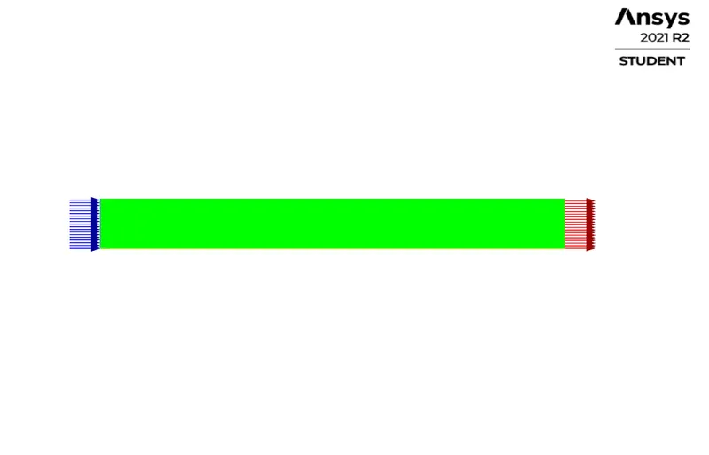
After that, the boundary conditions are set as follows:
- Air-Inlet
Velocity-Inlet
Velocity magnitude =0.5m/s
Temperature = 300 K
Species (mass Fraction)
Ch4……0
O2……..0.23
CO2…….0
H2O…….0
- Fuel-Inlet
Velocity-Inlet
Velocity magnitude =80m/s
Temperature = 300 K
Species (mass Fraction)
Ch4……1
O2……..0
CO2…….0
H2O…….0
- Outlet
Pressure-outlet
- Wall
Wall
- Wall-side
Wall
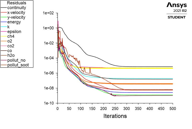
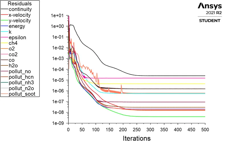
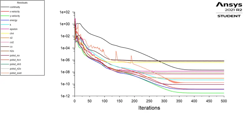
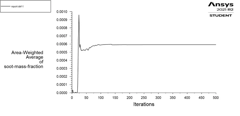
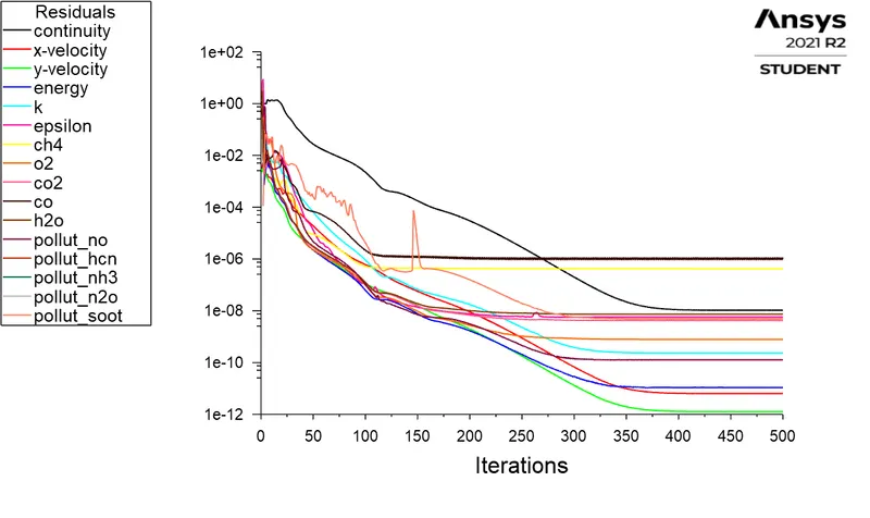
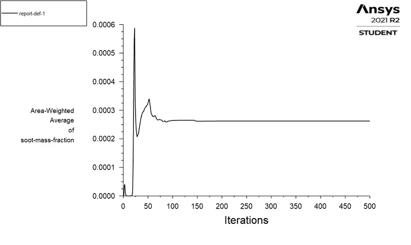
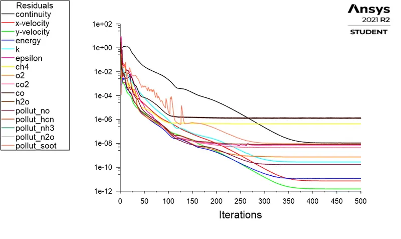
After that, the hybrid initialization is done and the simulation is run for 500 iterations.
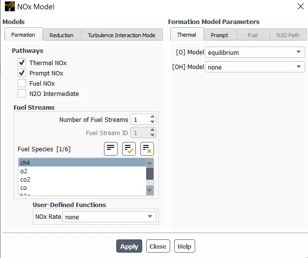
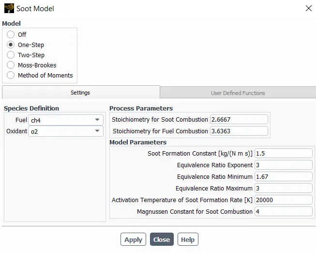
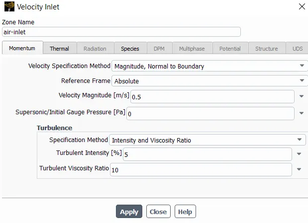
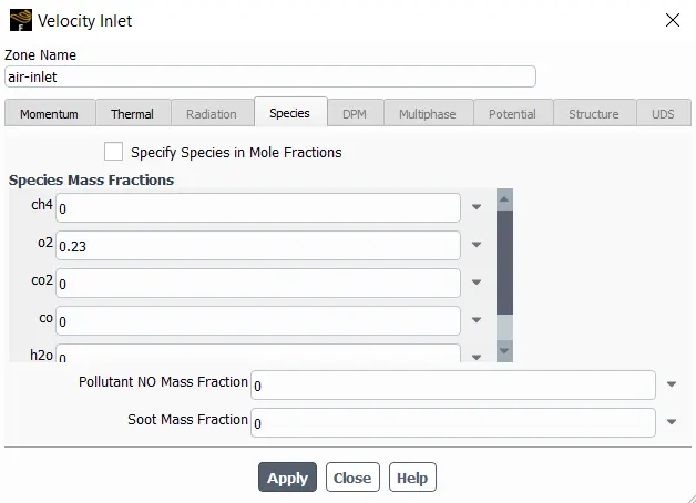
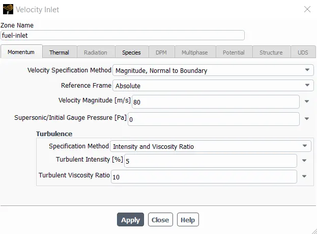
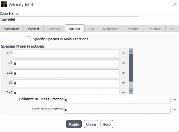
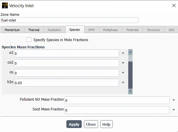
The above steps are strictly followed in the first part. In the second part, the same steps are followed except the fact that water is added to the fuel as shown in the image below.
Post-Processing
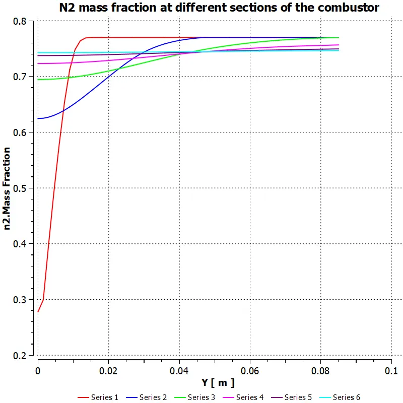
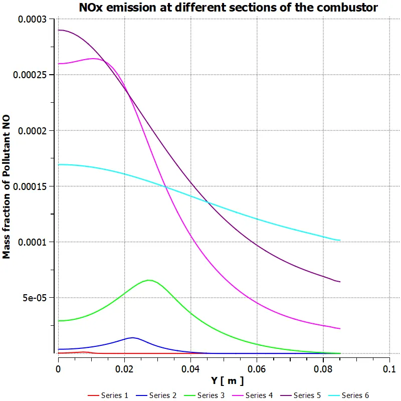
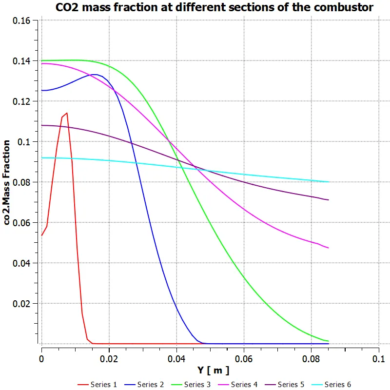
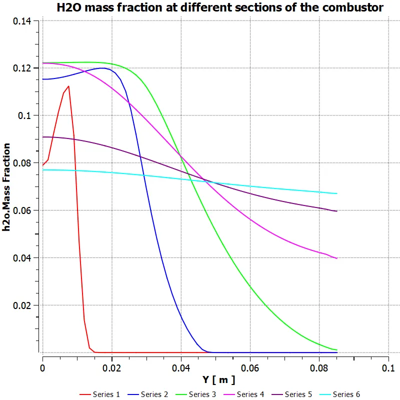
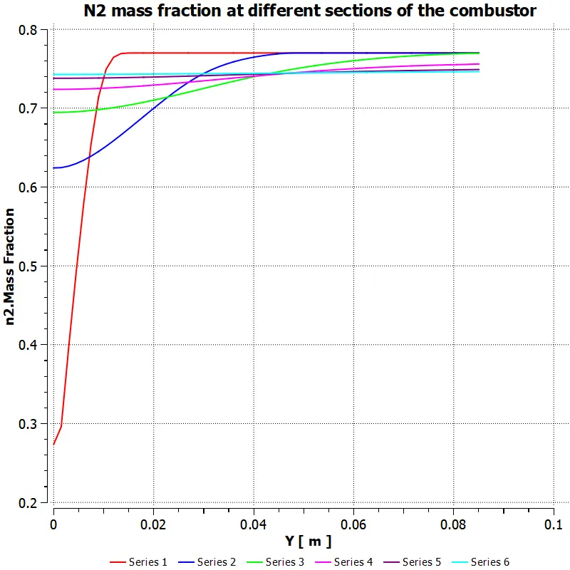
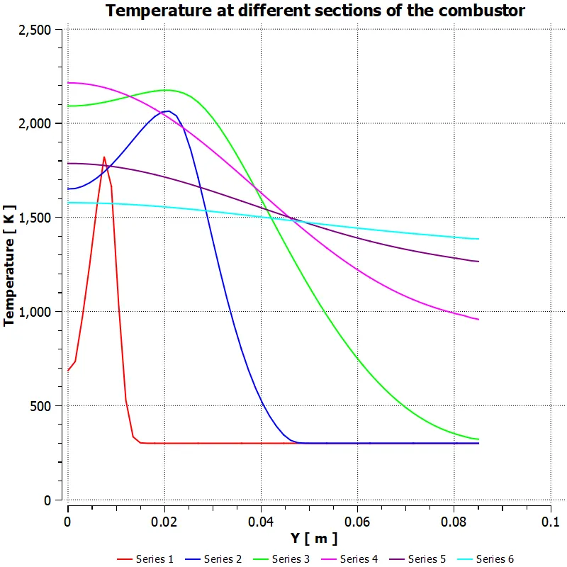
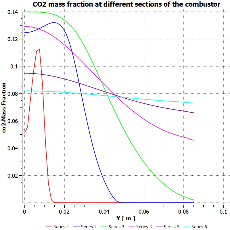
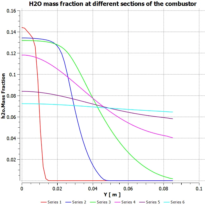
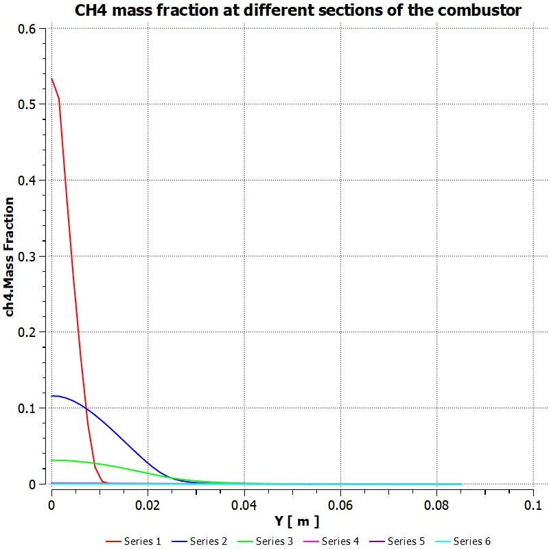
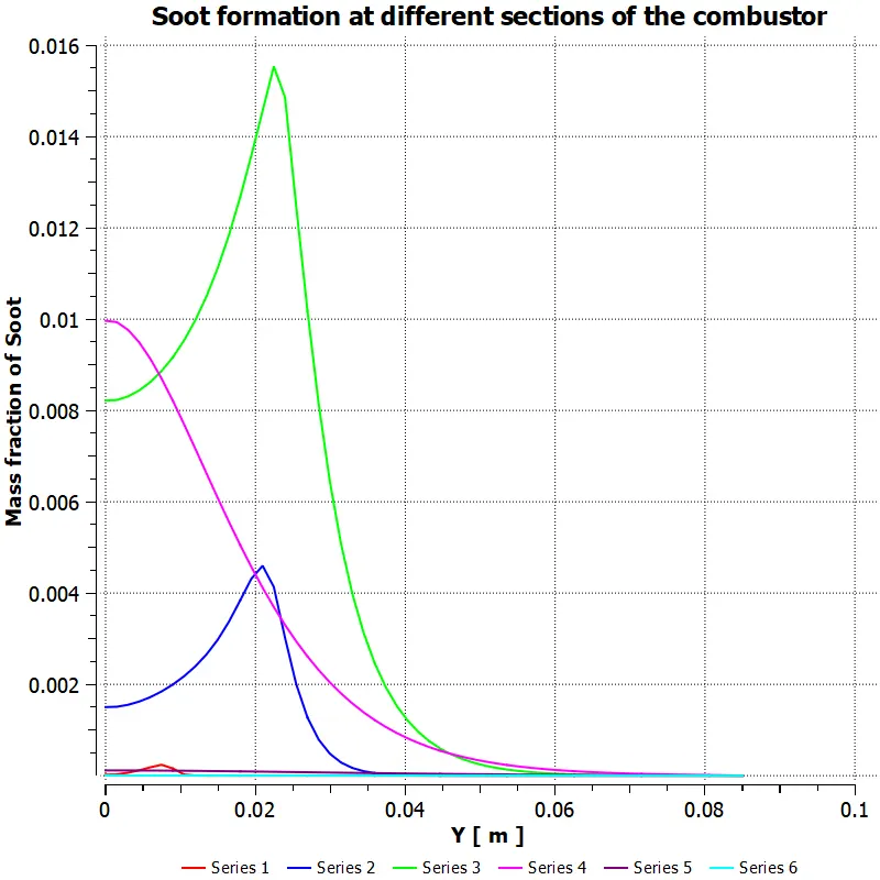
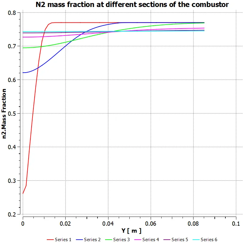
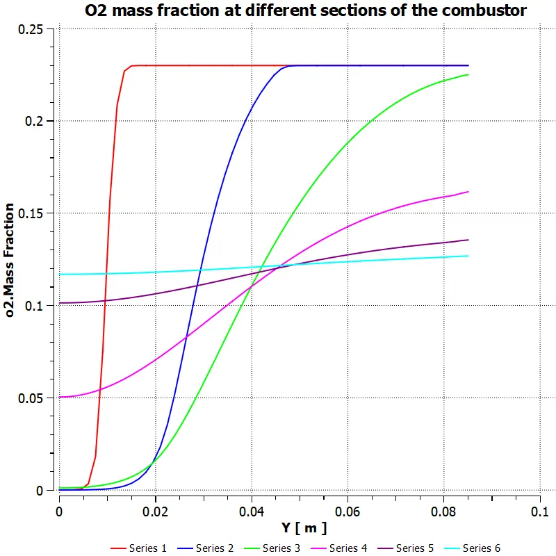
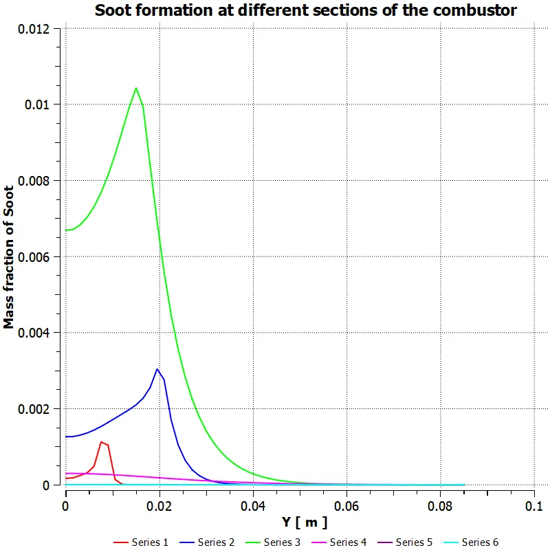
- Correspondence between line probes and legend data on different charts
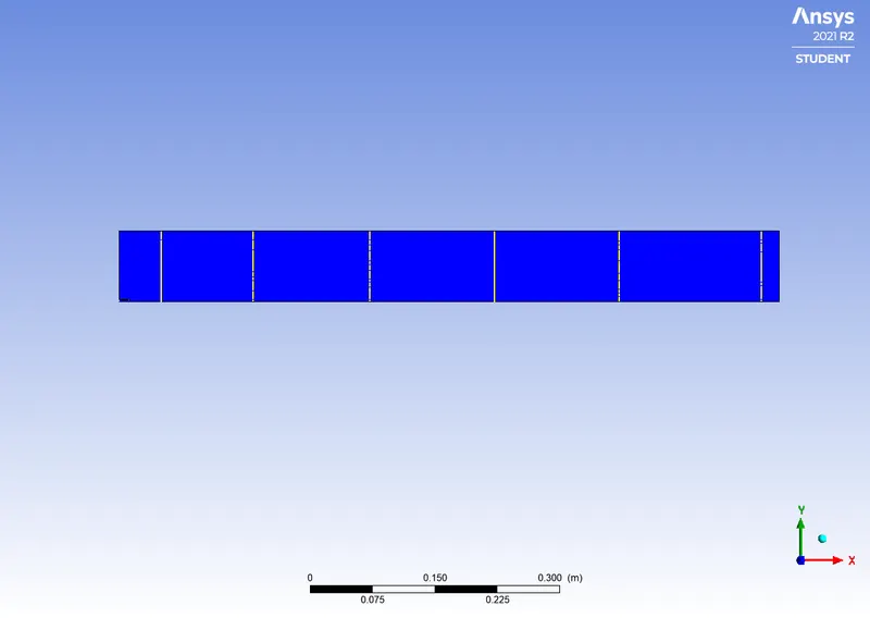
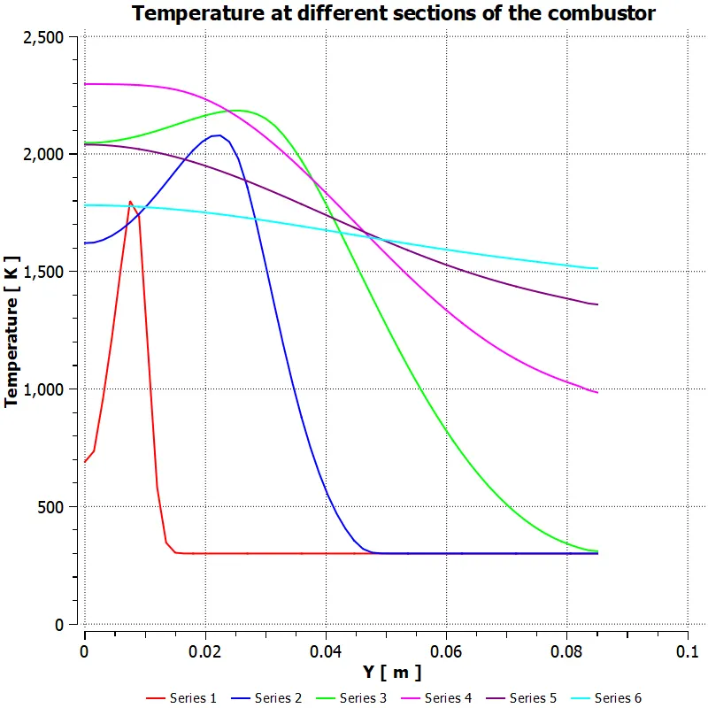
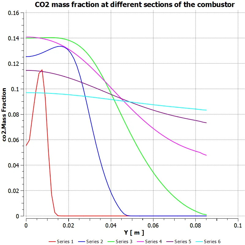
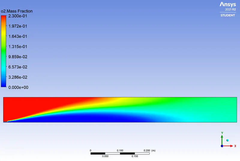
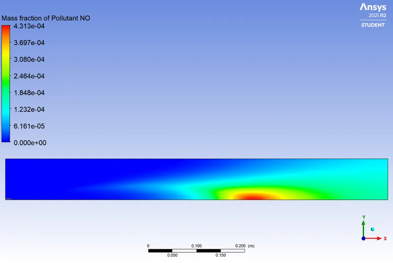
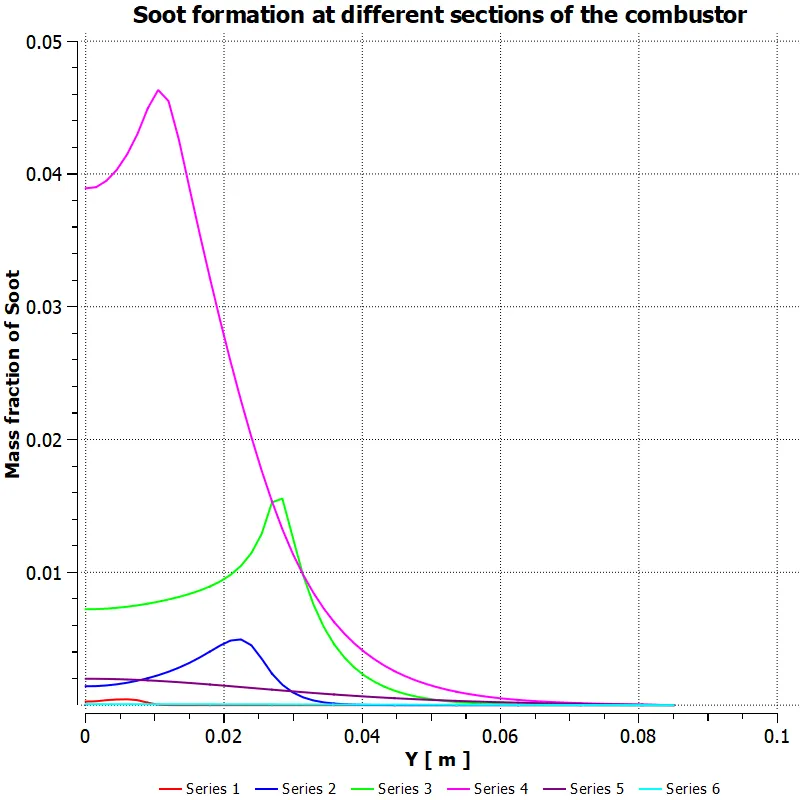
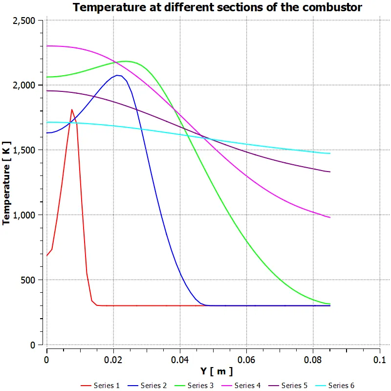
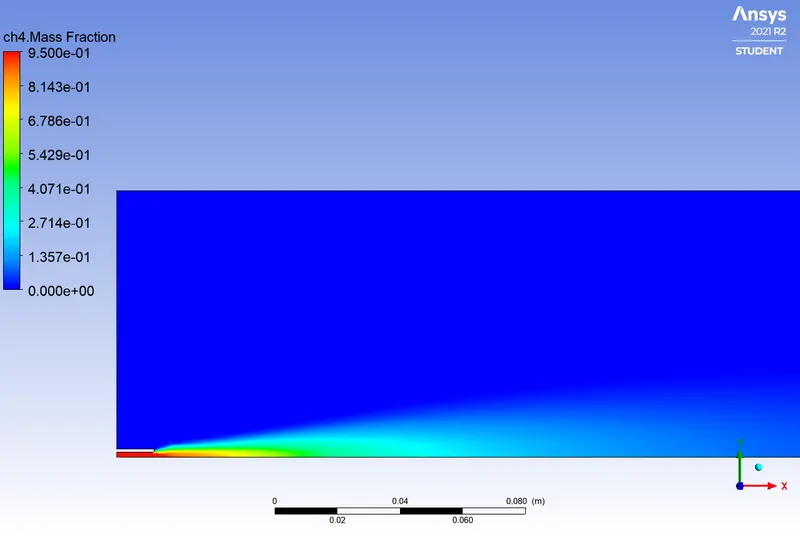
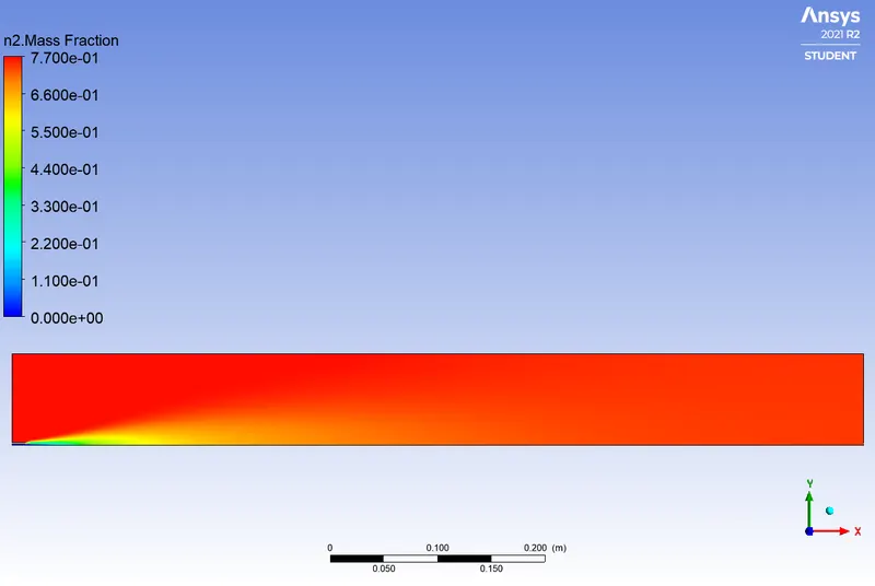
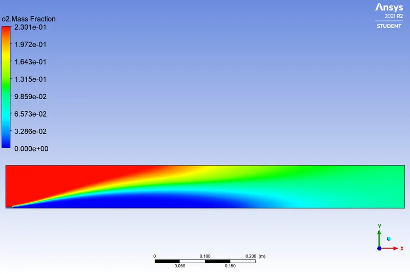
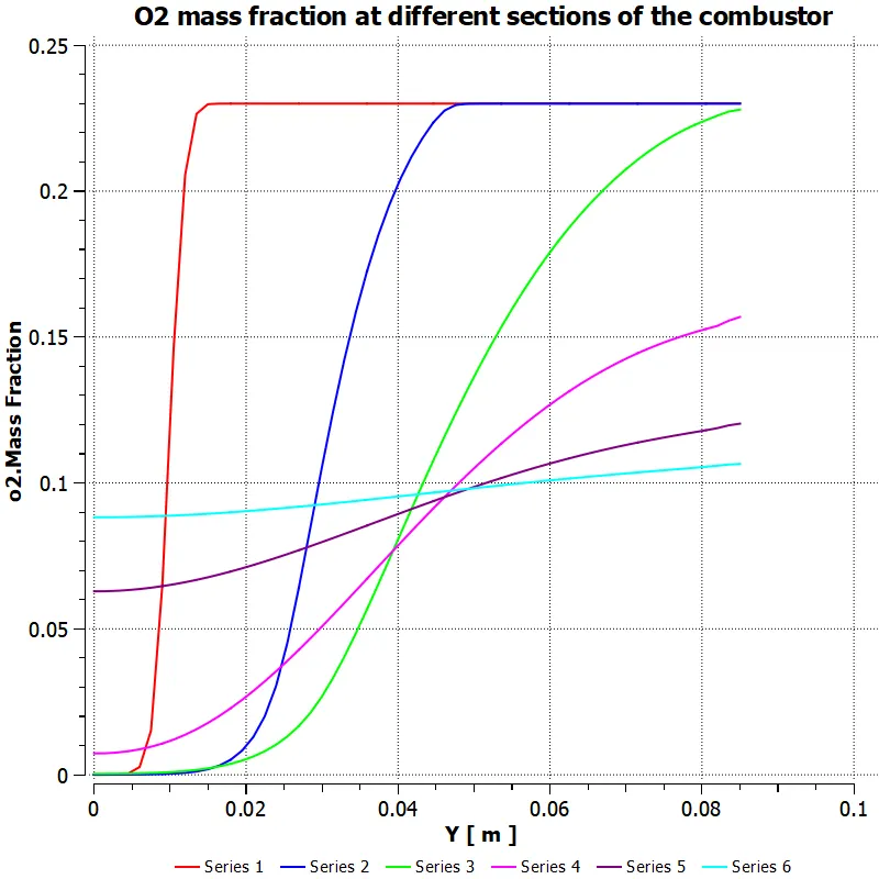
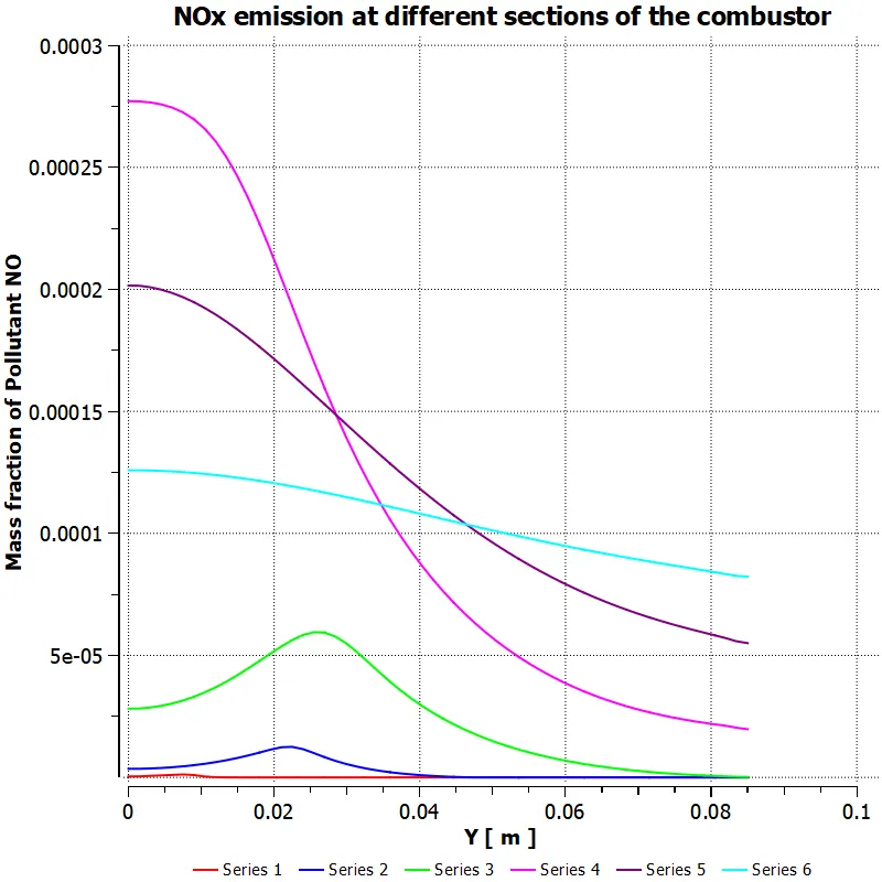
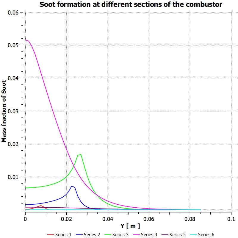
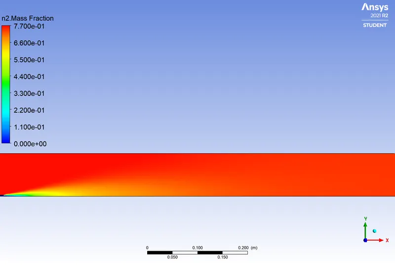
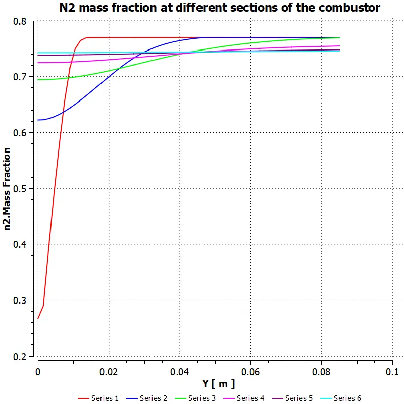
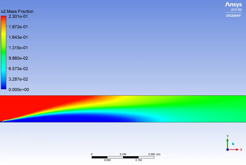
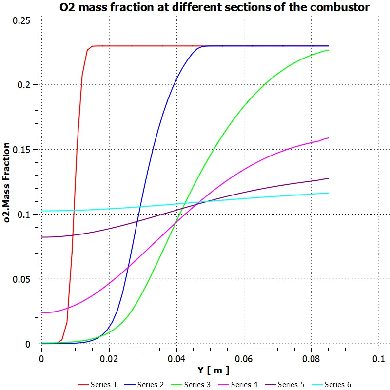
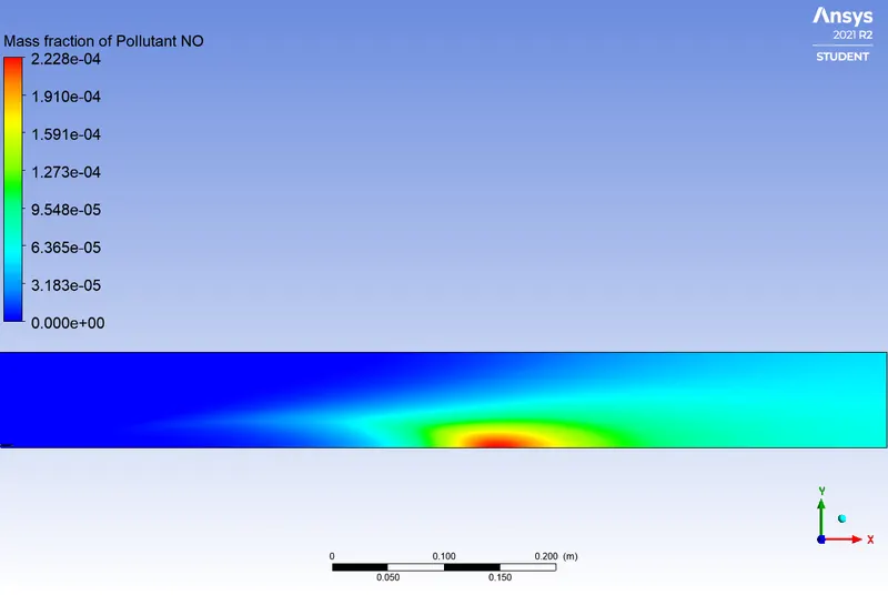
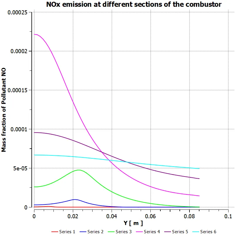
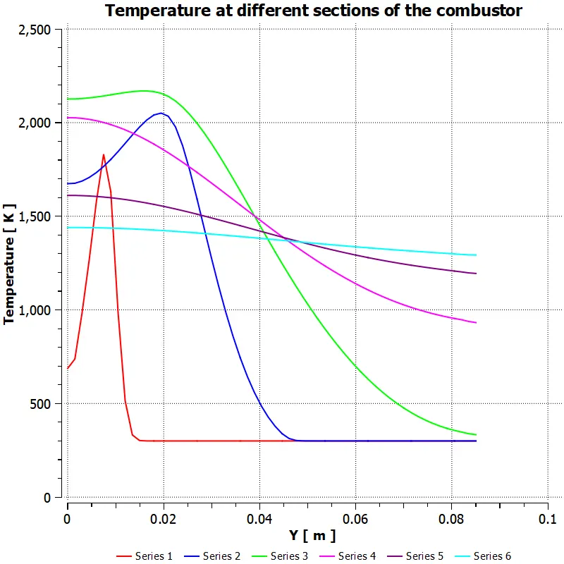
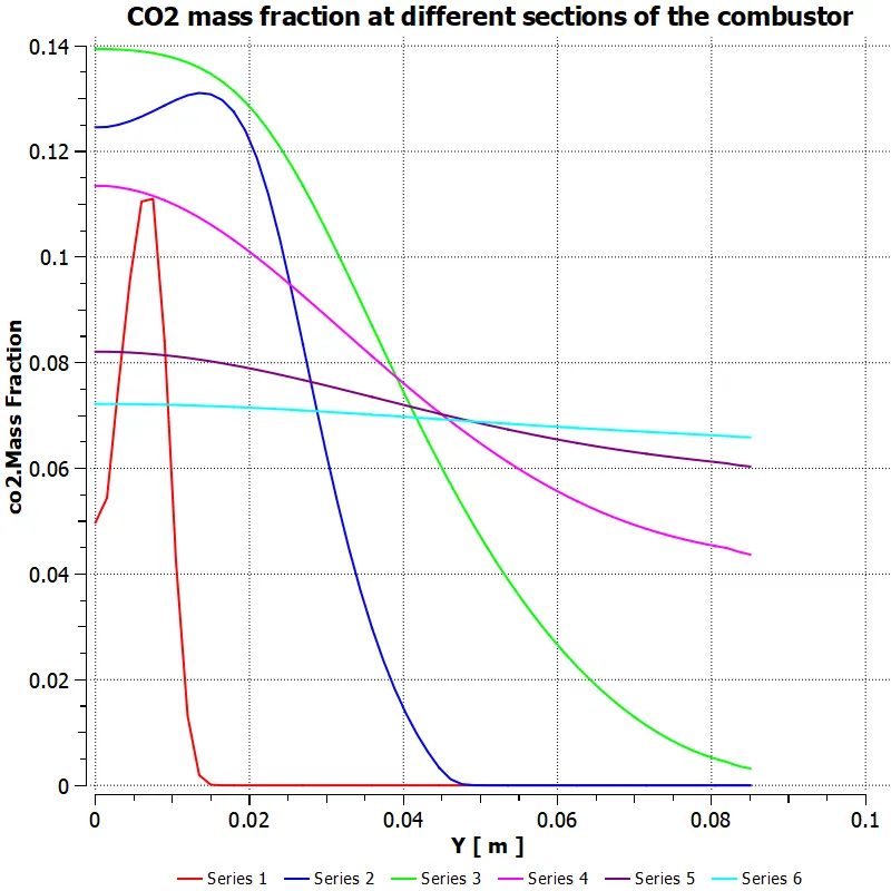
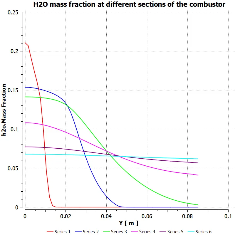
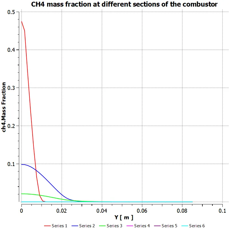
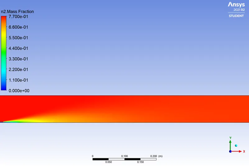
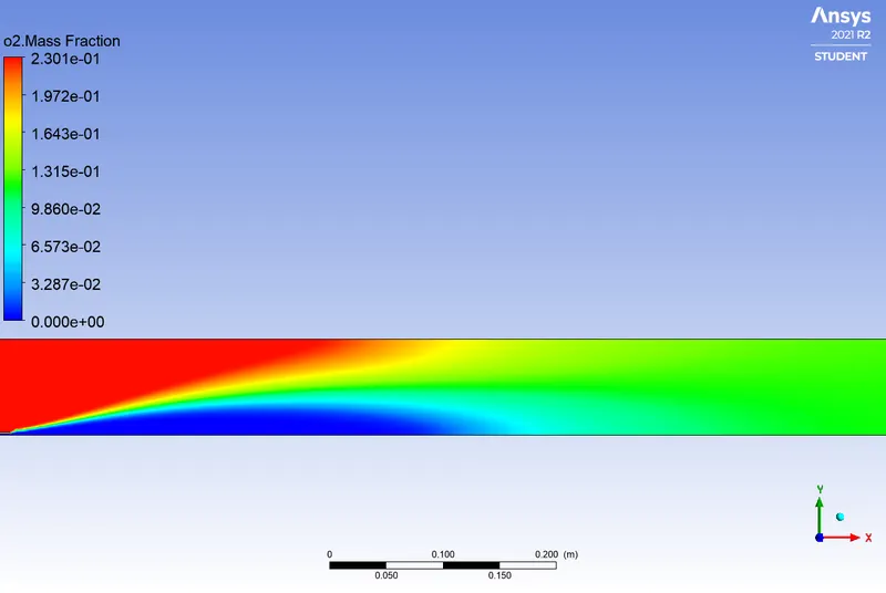
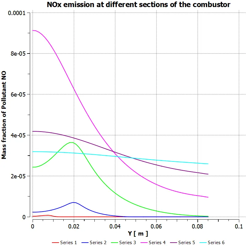
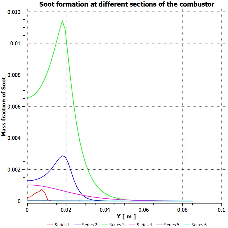
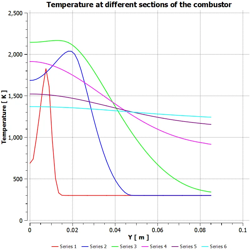
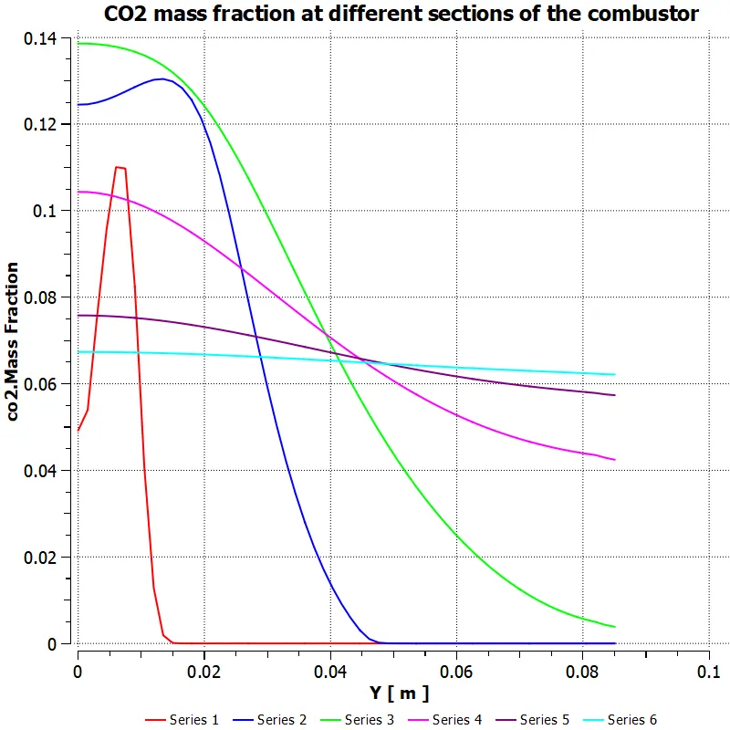
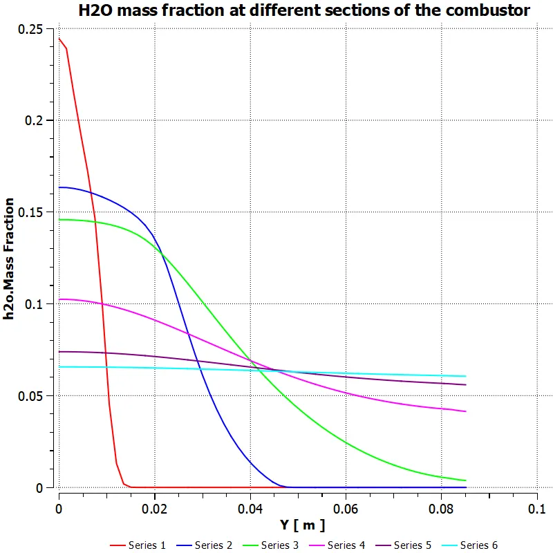
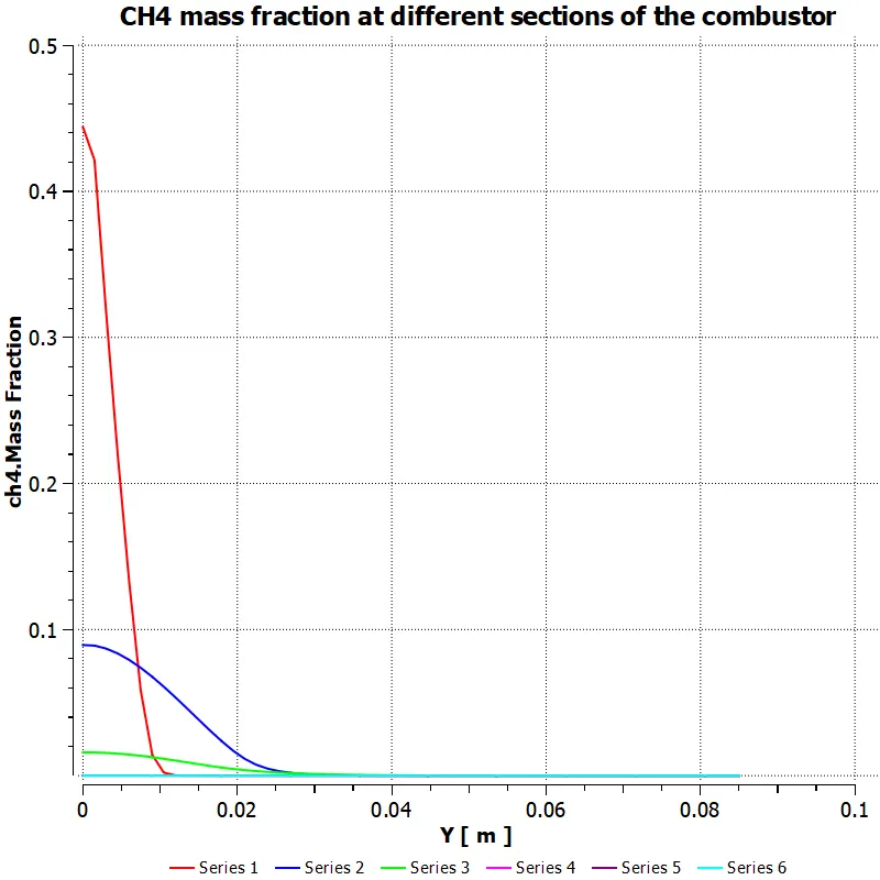
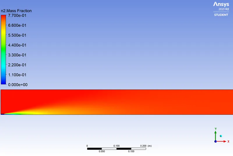
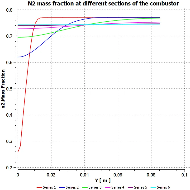
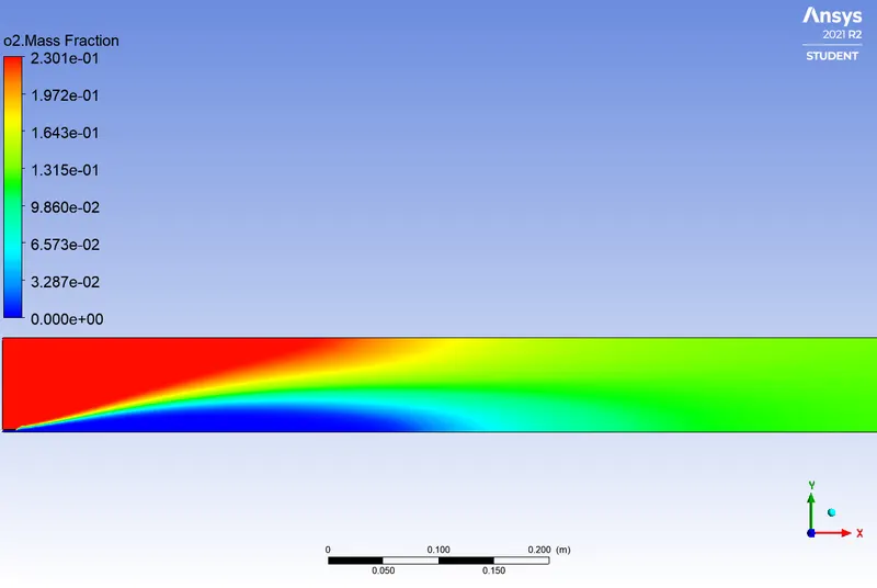
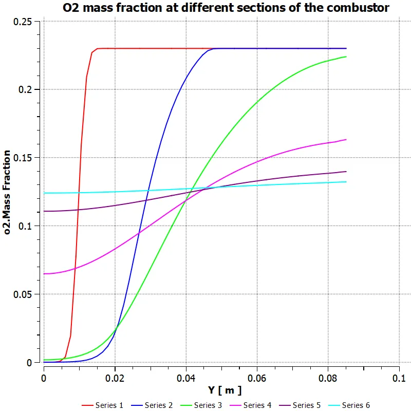
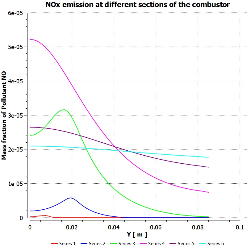
The line probes are used in order to plot the variation of mass fraction of each species. For that, two-point method is used to draw each line probe in XY-plane. The coordinates as well as corresponding legend data are shown in the table below.
|
Line Name |
First point coordinates |
Second point coordinates |
Corresponding legend |
|
Line 1 |
(0.05,0,0) |
(0.05,1,0) |
Series 1 |
|
Line 2 |
(0.16,0,0) |
(0.16,1,0) |
Series 2 |
|
Line 3 |
(0.3,0,0) |
(0.3,1,0) |
Series 3 |
|
Line 4 |
(0.45,0,0) |
(0.45,1,0) |
Series 4 |
|
Line 5 |
(0.6,0,0) |
(0.6,1,0) |
Series 5 |
|
Line 6 |
(0.77,0,0) |
(0.77,1,0) |
Series 6 |
PArt 1
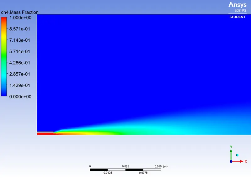
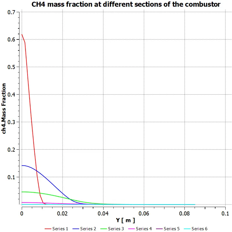
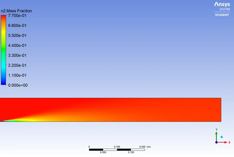
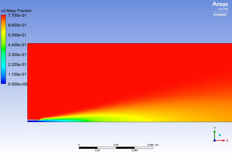
Part 2
- Case 1 Water is added to the fuel at a level of 5%
- Case 2 Water is added to the fuel at a level of 15%

- Case 3 Water is added to the fuel at a level of 25%
- CAse 4 Water is added to the fuel at a level of 30%
|
Water addition level (%) |
Ratio of Methane and water mixed (CH4:H2O) |
Mass Fraction of NOx emission |
Mass fraction of Soot formation |
|
5 |
0.95:0.05 |
4.7283908e-05 |
0.0010359812 |
|
15 |
0.85:0.15 |
2.864962e-05 |
0.00059251248 |
|
25 |
0.75:0.25 |
1.5289844e-05 |
0.00026225216 |
|
30 |
0.7:0.3 |
1.0539404e-05 |
0.00016897192 |
Discussion
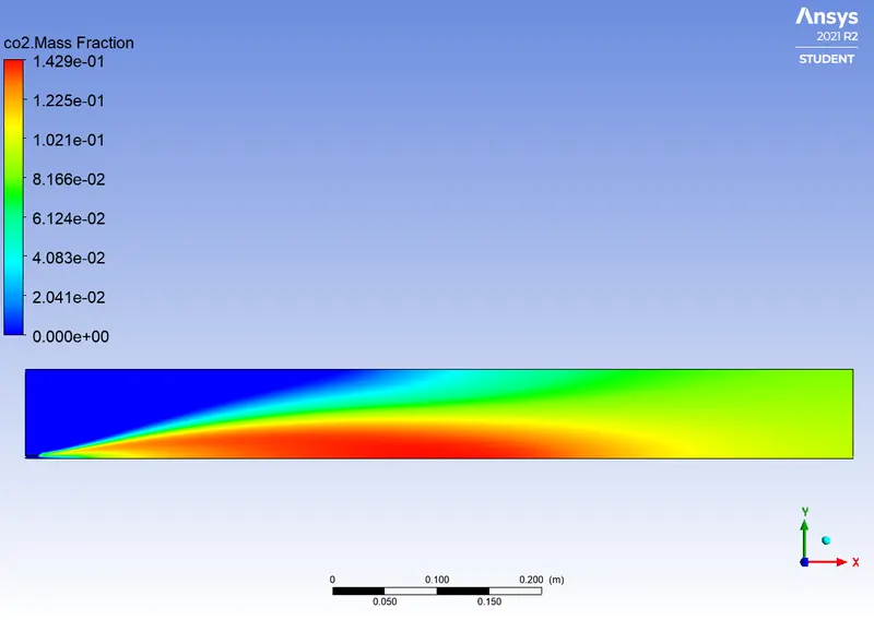
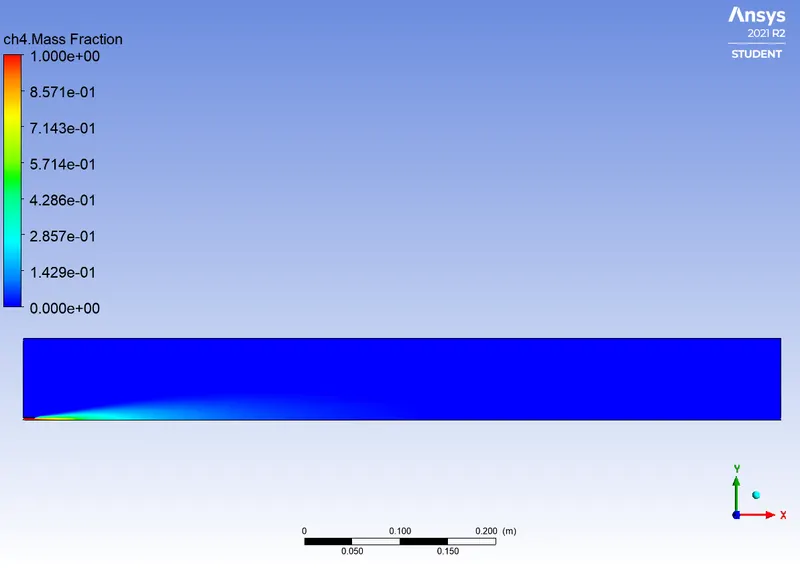
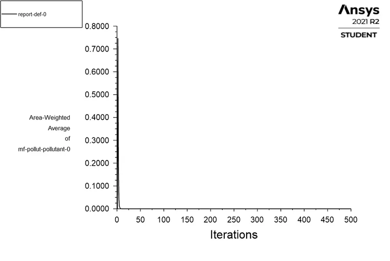
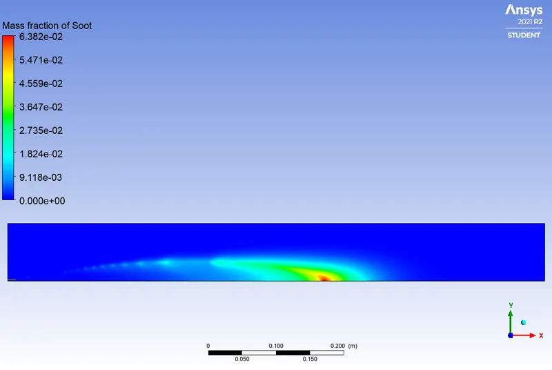
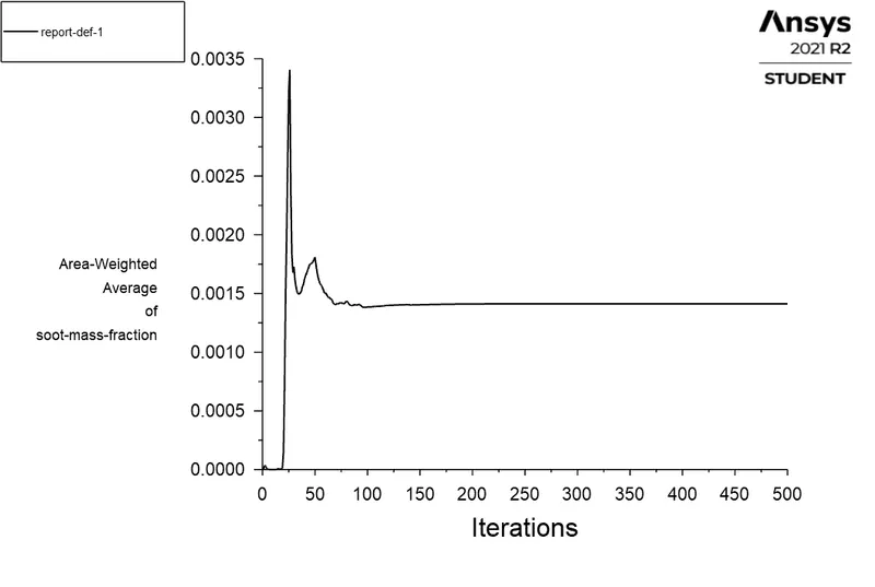
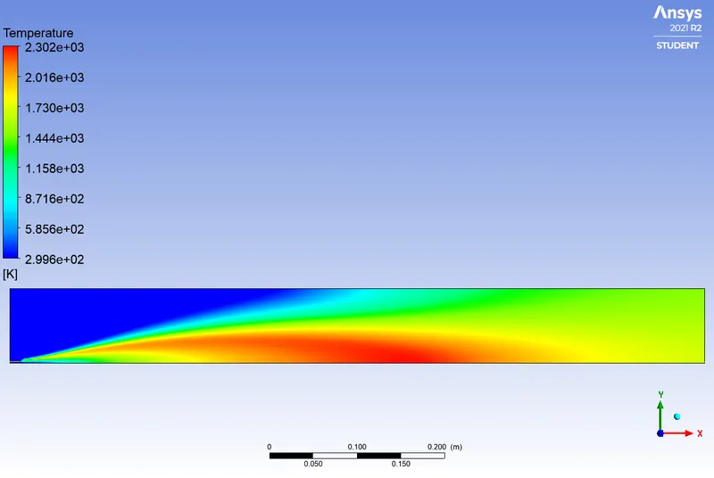
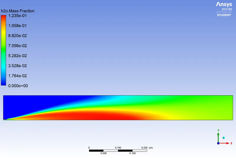
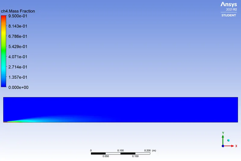
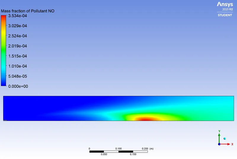
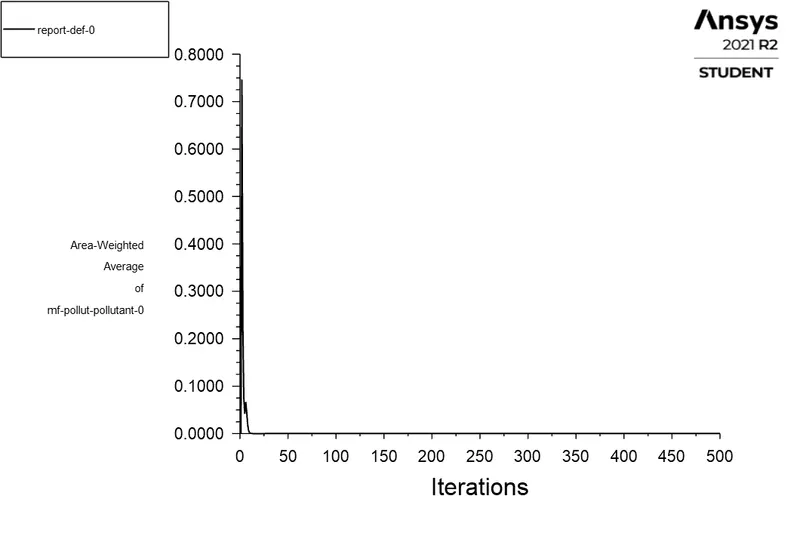
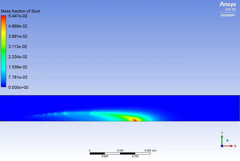
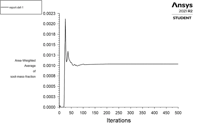
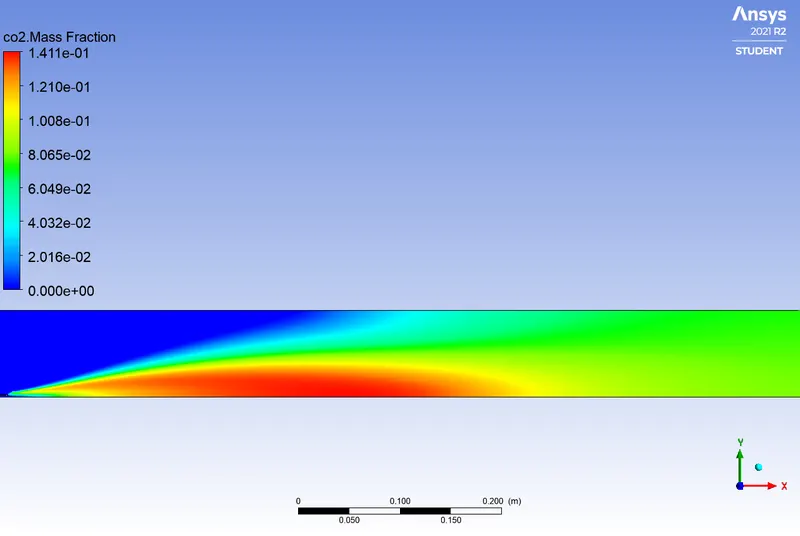
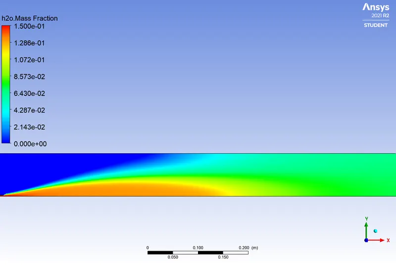
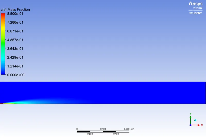
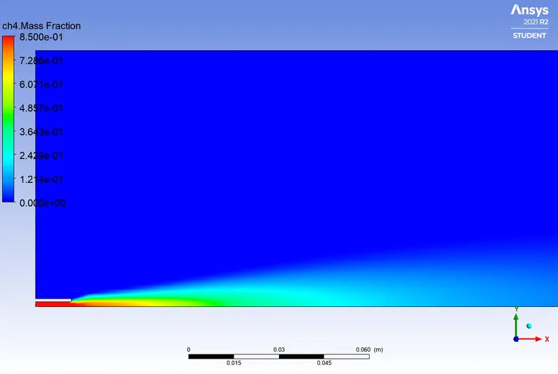
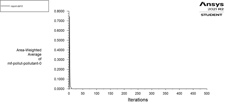
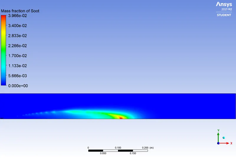
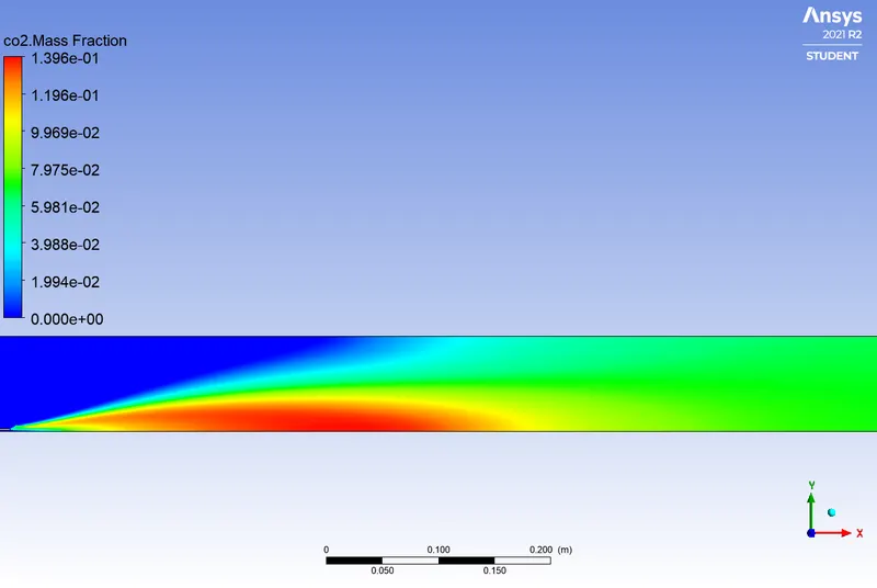
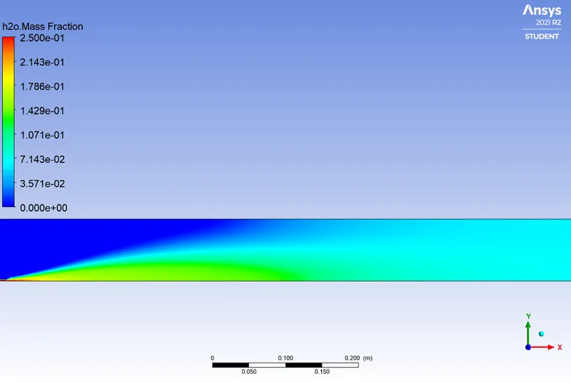
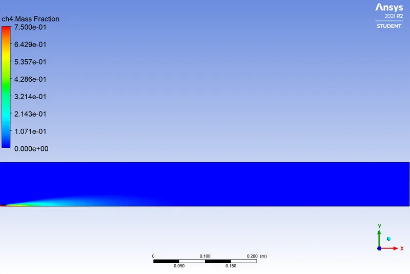
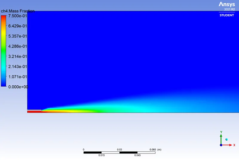
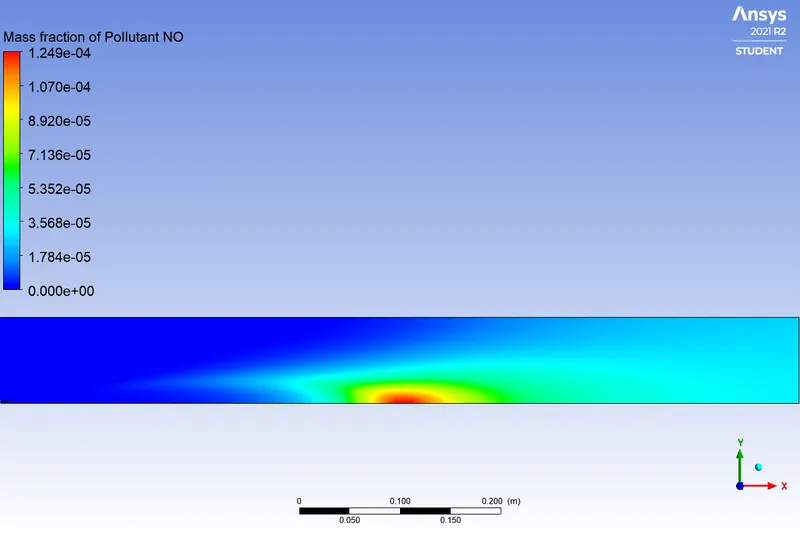
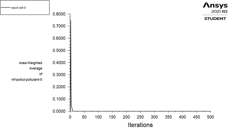
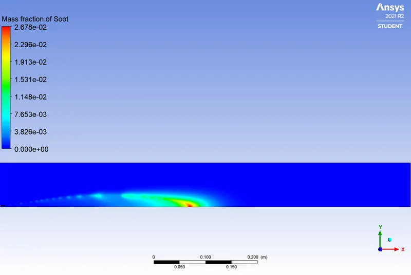
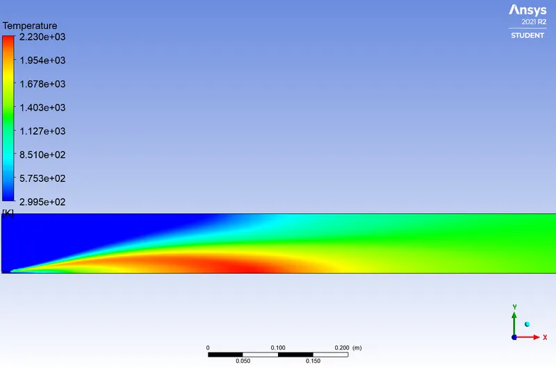
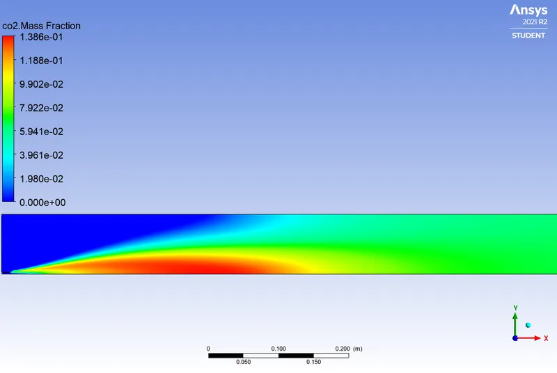
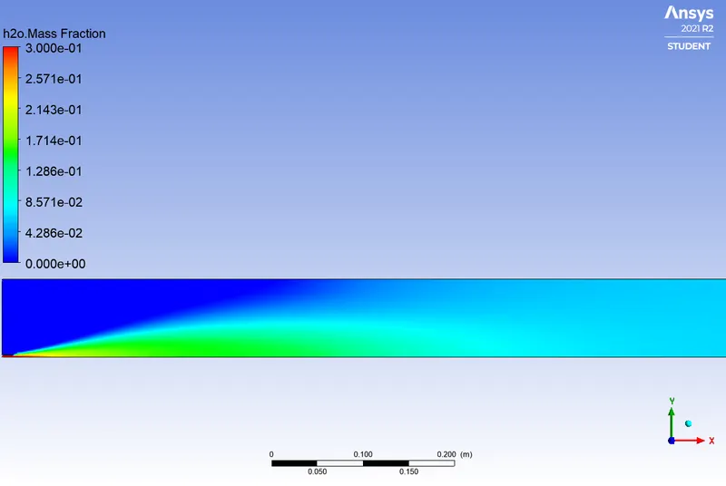
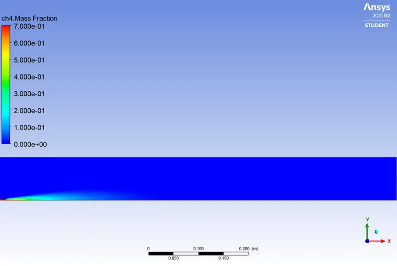
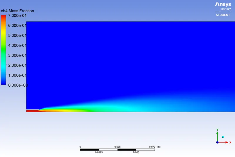
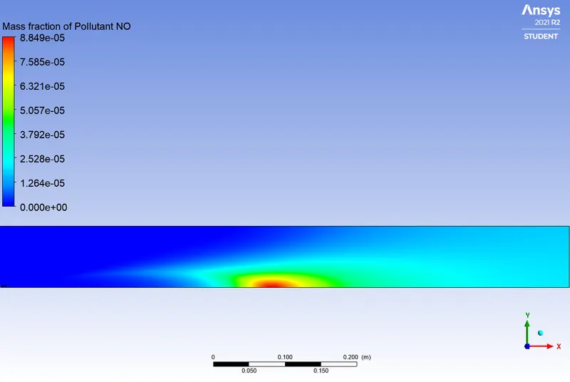
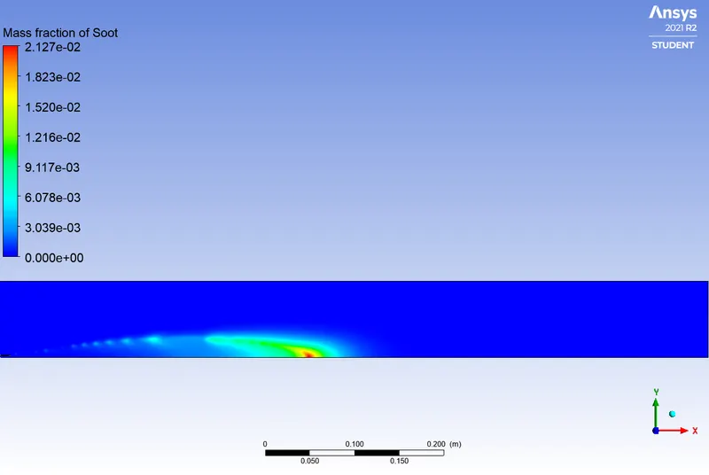
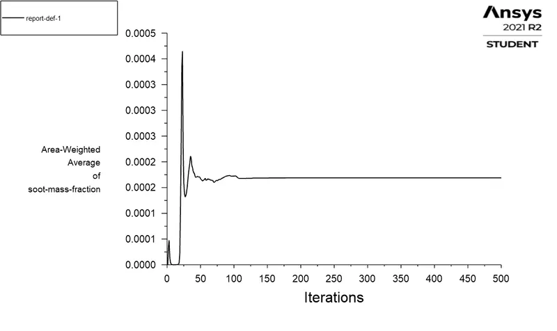
As it can be seen in the above images, in the first part of the project, NOx is emitted and Soot is formed. The value of NOx emission obtained is 5.8502393e-05 and the one for Soot formation is 0.00141194. These formations have harmful effects on the environment and humans. The stringent government norms also demand the least formation of NOx and Soot. Thus, as stated in the beginning, the objective of the second part of our work, is to reduce the NOx emission and Soot formation at the outlet of the combustor by injecting water to the fuel. Water is then added for different levels basically 5%, 15%, 25% and 30% in terms of mass fraction. The contours for different species namely CO2, H2O, CH4, N2, O2, NOx and Soot formation are observed and the mass fraction variation is also plotted.
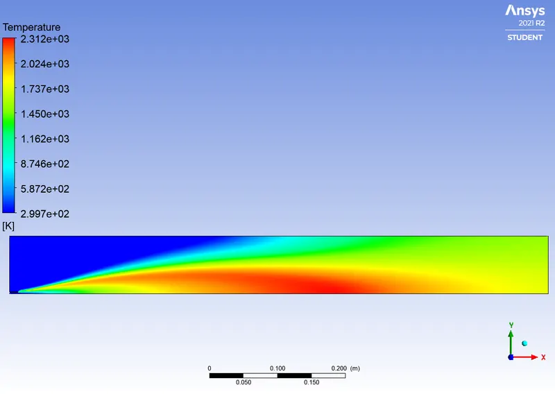
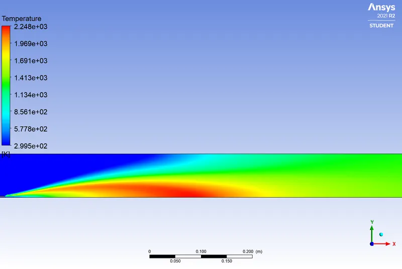
We can notice throughout the results that the temperature peaks are constantly decreasing during the combustion as the quantity of injected water increases. The highest temperature is achieved in the proximity of the inlet, where the stoichiometric conditions are achieved due to the mixing between fuel and air streams and the temperature at the outlet is uniform. This is explained by the fact that, the water supplied into the combustor causes the increase of self-ignition delay which affects the flammable mixture that becomes more homogeneous in the whole volume of the combustor. The increased self-ignition delay extends the time necessary to spread the injected fuel which results in fewer zones with not enough oxygen. This phenomenon decreases the intensity of Soot and CO formation. In fact, emulsifying the mixture reduces local zones with temperature peaks which leads to decreasing nitrogen activity and NOx concentration.
As described, in order to obtain the allowed level of NOx emission at the outlet of the combustor, it is necessary to inhibit the process of NOx formation in the combustor. The influence of water on the NOx reduction process during combustion results from two factors.
- Water supplied into the combustion chamber, apart from lowering the combustion temperature also decreases the concentration of atomic oxygen by the reaction below:
H2O → OH + H
H2O + O → OH + OH
H2 + O → H + OH
H + O2 → OH + O
This influences the reaction speed as follows:
O + N2 → NO + N
O + N2 + OH ↔ N2O + OH
- The resulted OH is more difficult to interact with atomic N, which as a consequence significantly lowers the amount of NO.
Conclusion:
Finally, the combustion simulation of natural gas is carried out and different parameters are observed: the mass fraction variation, the temperature contours. The NOx emission as well as Soot formation are evaluated. These gases considered as side effect associated to combustion processes characterized by high temperature and rich conditions entail a reduction in the efficiency of the combustor as well as a detrimental effect on climate change and human health. Throughout the work done in this project, it is clearly observed that water injection into the fuel is an effective way to reduce NOx emission and Soot formation. However, the investigation of different modelling strategies for Soot formation as well as different systems of water supply into the combustion chamber can be discussed further.
References