Week 10 - Simulating Combustion of Natural Gas.
AIM:To perform a non-premixed combustion simulation of natural gas on a combustor model.
OBJECTIVE: To plot the variation of the mass fraction of the different species in the simulation using line probe at different location.
INTRODUCTION:
- Simulation of combustion is based on mixing of air and fuel and also based on phase.
- Non-pemixed: if air and fuel is not properly mixed(direct injection,late injection).
- Premixed combustion:spark ignition (gasoline engine).
- In non-premixed flame ,the fuel and oxidizer are separated before entering the reaction zone where they mix and burn.
- The combustion reactions in such cases are called non-premixed flames or diffusion flames, because the fuel and oxidizer are transported independently into the reaction zone occurs primarily by diffusion flame.
- Chemical reactions between fuel and oxidizer occur only at the molecular level,so mixing betwwen fuel and oxidizer must take place before combustion.
- As the chemical reactions are fast,hence the burning rate is limited by the transport and mixing process rather than by chemical kinetics.
- Greater flame stability is obtained with this flame.
Mechanism for NO formation
- Thermal NO( Zeldovich mechanism)
- Prompt NO(Fenimore): NOx can be produced promptly at the flame front by CH radical.
CH radical is an intermediate species produced ony at the flame front at relatively low temperature.CH radicals react with N2
molecules with the following sequence of steps.
CH +N2 = HCN +N
HCN + N`rarr` `rarr`NO
- N2O route
- FBN( fuel bound notrogen)
Soot Formation
- Starts with pyrolysis of fuel molecules in the rich parts of flames and formation of polycylic aromatic hydrocarbons(PAH).
- It consists of agglomerates with diameter of upto several hundred nanometer.
Three distinct steps used to model soot in flames:
- Nucleation
- agglomeration
- Oxidation
CH4 + ar( O2 + 3.76N2) `rarr`aCO2 +bH2O + cN2 , ar = number of moles of (O2 +3.76N2)
- Fuel = 1 mole of CH4
- oxidizer (air) = 2 moles of O2 + 7.52 moles of N2
MODELLING APPROACH
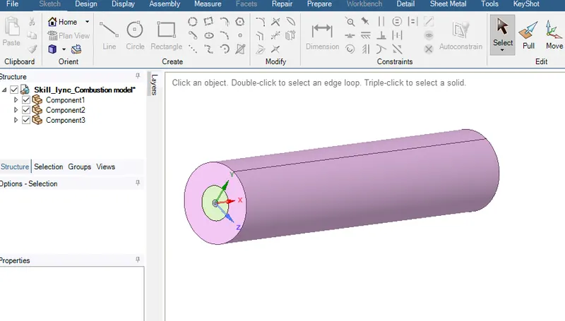
Fig.1 combuster model
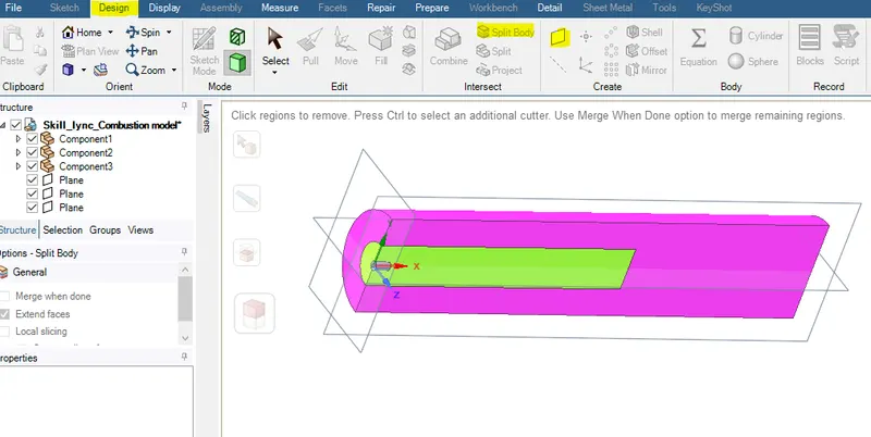
Fig.2 split body command is used for 2D geometry
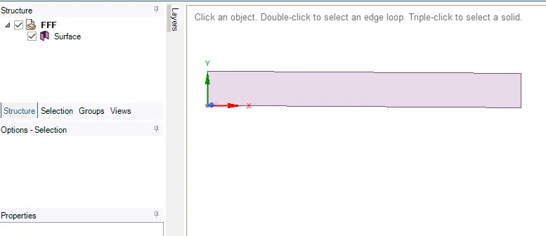
Fig.3 2D geometry is created
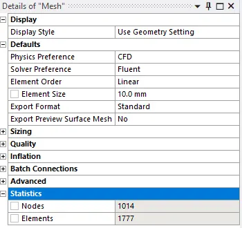
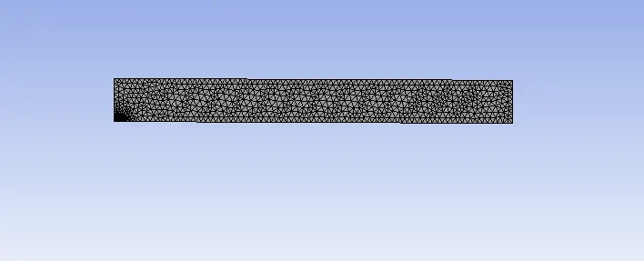
Fig.4 mesh
PREPROCESSING AND SOLVER SETING:
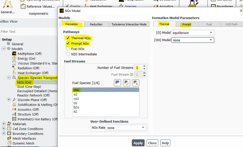
Fig.5 NOx model
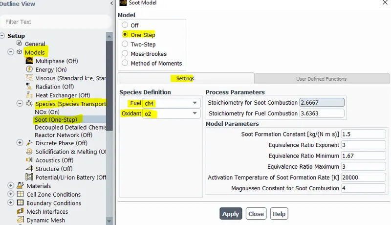
Fig.6 Soot Model
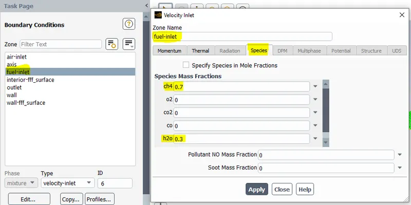
Fig.7 species mass fraction for fuel inlet
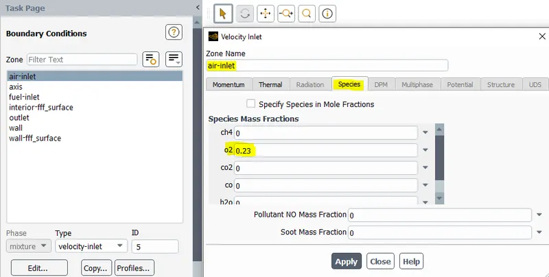
Fig.8 species in mass fraction for air-inlet
Boundary condition:
- inlet = velocity
- Air inlet velocity= 0.5 m/s
- thermal(temp.) = 300k
- Fuel inlet velocity = 80 m/s
- Outlet = pressure outlet
- Viscous = k-epsilon model
- Solver= Pressure based
- energy = ON
- species = eddy dissipation, volumetric mass fraction, methane -air two step material
RESULTS
PART 1
Fuel: CH4
oxidizer: air
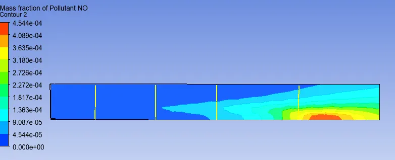
Fig. 1 mass fraction of NO
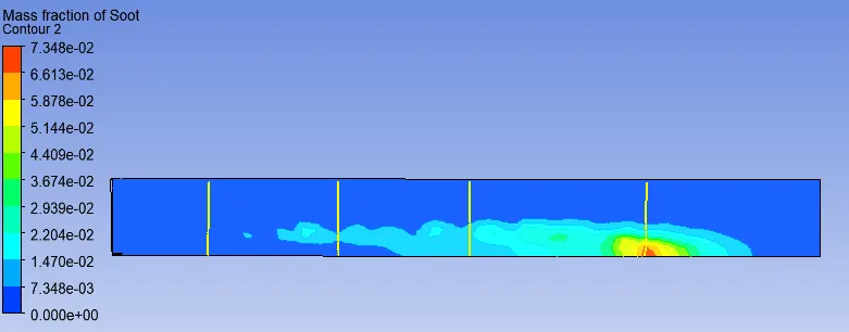
Fig. 2 mass fraction of soot
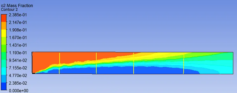
Fig. 3 mass fraction of O2
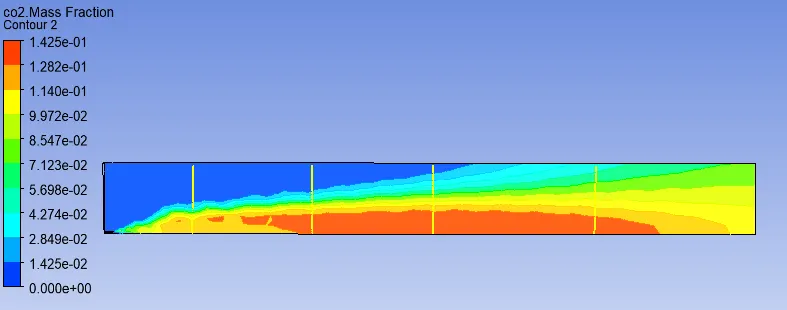
Fig. 4 mass fraction of CO2
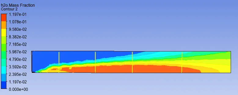
Fig. 5 mass fraction of H2O
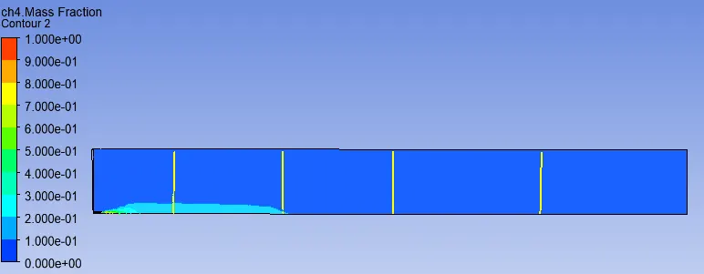
Fig. 6 mass fraction of CH4
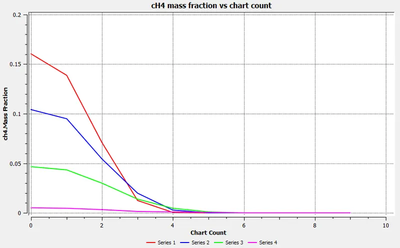
Fig. 7
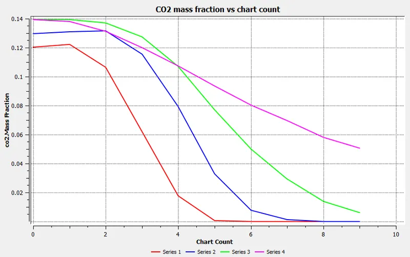
Fig. 8
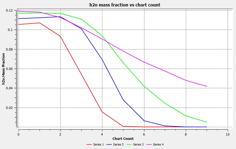
Fig. 9
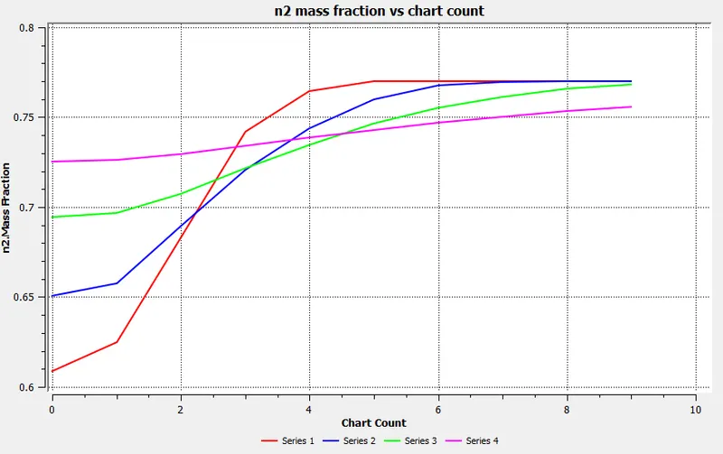
Fig. 10
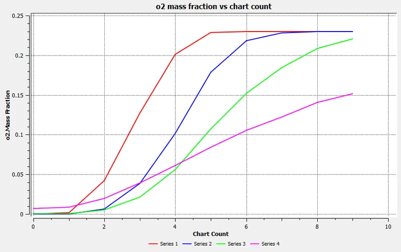
Fig. 11
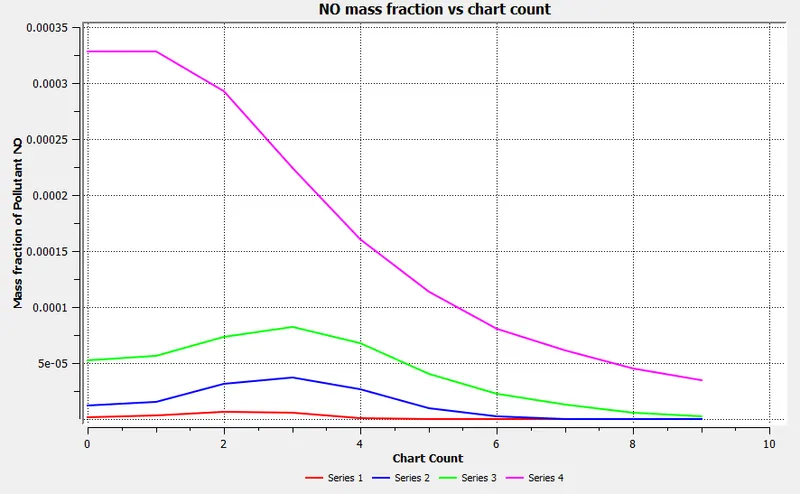
Fig. 12
- NO concentration is found to be more at the downstream of flame as the temperature their is maximum as compared to the upstream of combustion .
- Part of NO is converted into NO2 in the cold region of combustor.From the graph it is shown that O2 concentration is maximum at the upstream of combustor.
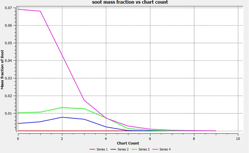
Fig. 13
PART 2
Fuel inlet: 90% CH4 and 10% H2O
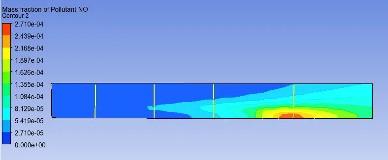
Fig. 14 mass fraction of NO
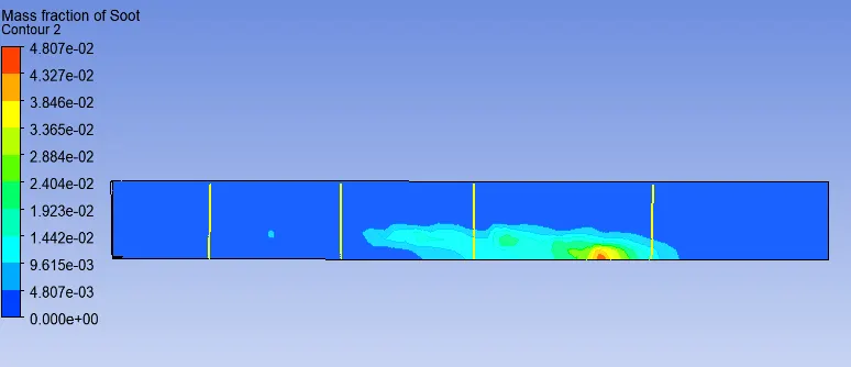
Fig. 15 mass fraction of Soot
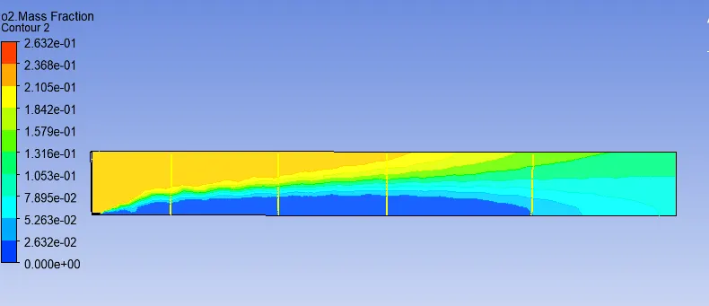
Fig. 16 mass fraction of O2
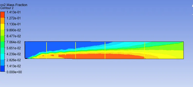
Fig. 17 mass fraction of CO2
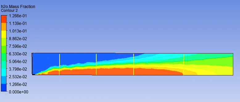
Fig. 18 mass fraction of H2O
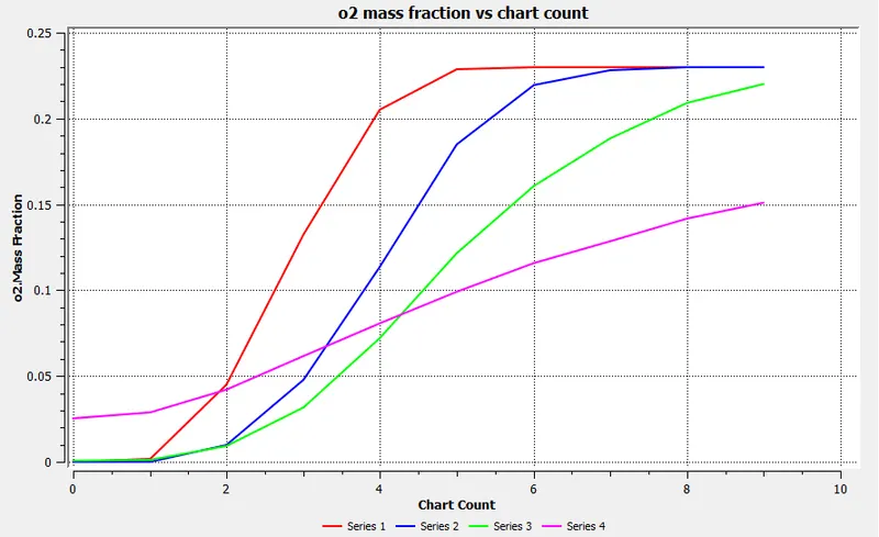
Fig. 19
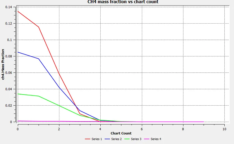
Fig. 20
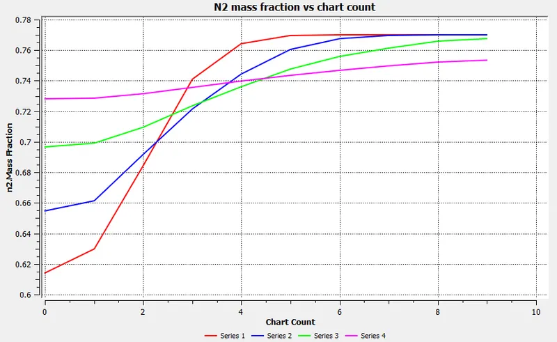
Fig. 21
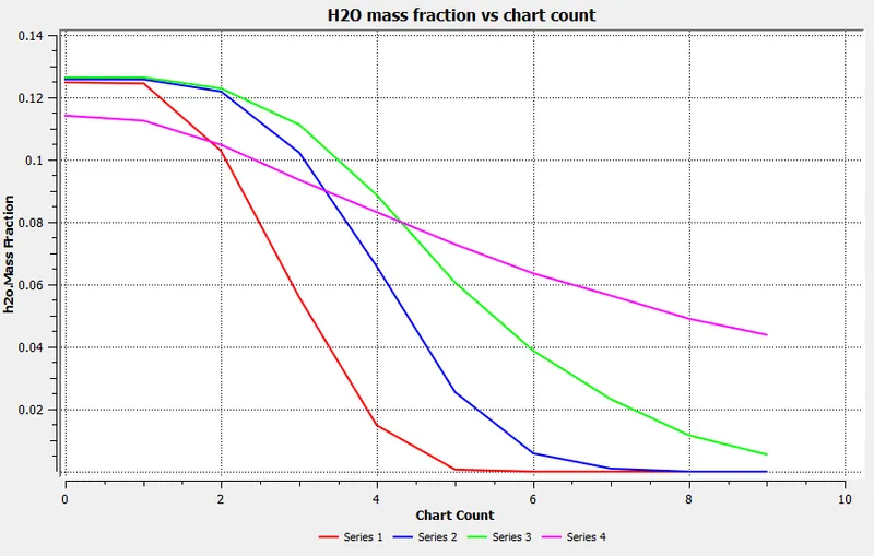
Fig. 22
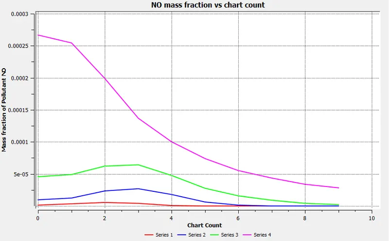
Fig. 23
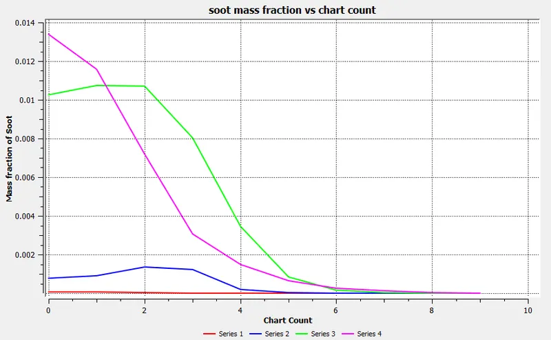
Fig. 24
Fuel inlet : 80% CH4 and 20% H2O
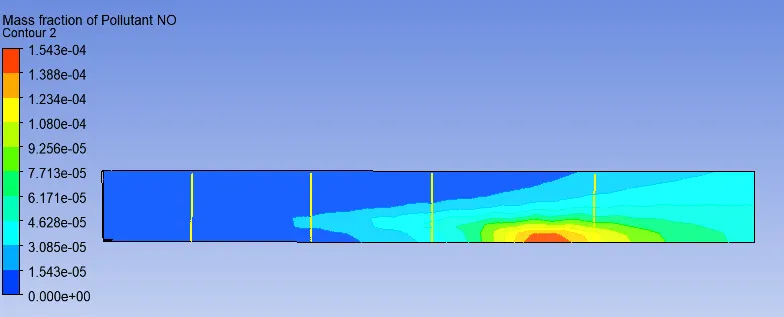
Fig. 25 mass fraction of NO
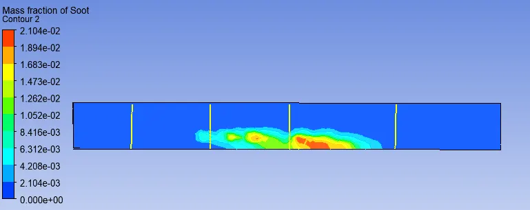
Fig. 26 mass fraction of soot
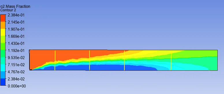
Fig. 27 mass fraction of O2
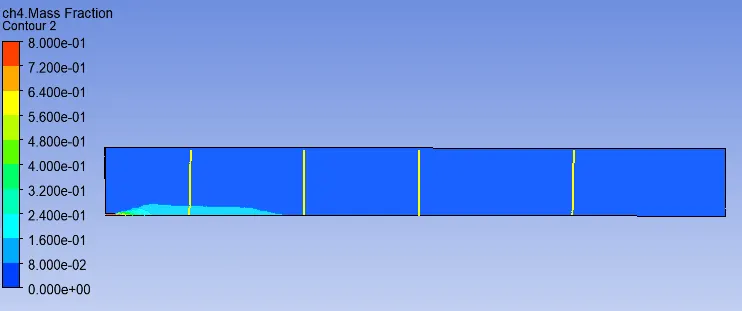
Fig. 28 mass fraction of CH4
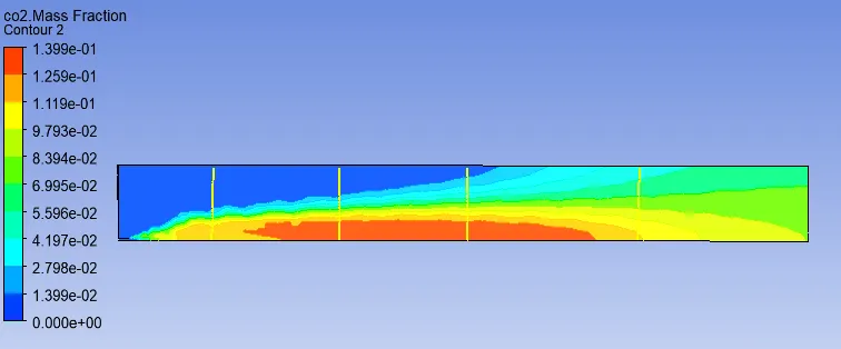
Fig. 29 mass fraction of CO2
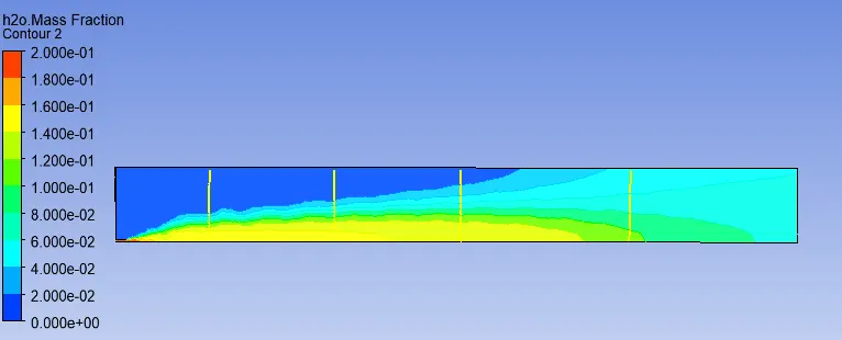
Fig. 30 mass fraction of H2O
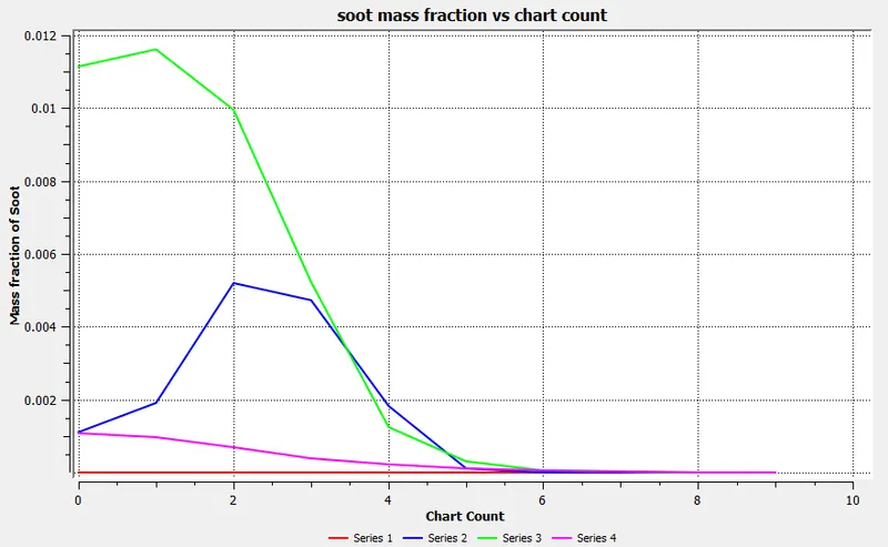
Fig. 31
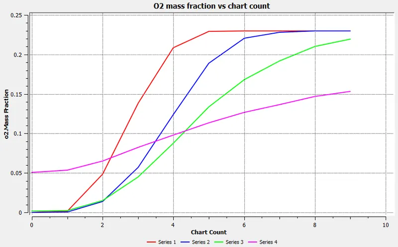
Fig. 32
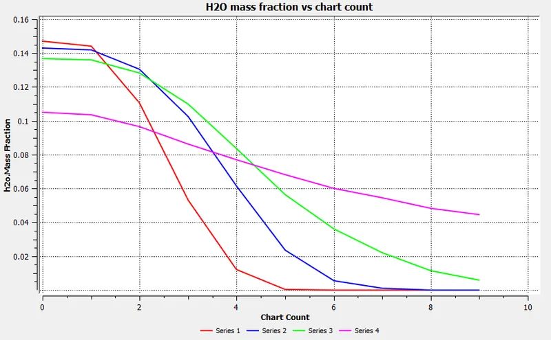
Fig. 33
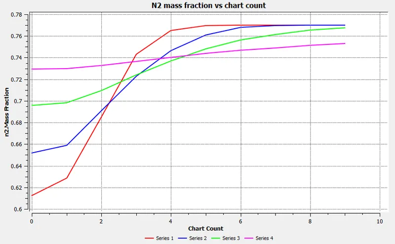
Fig. 34
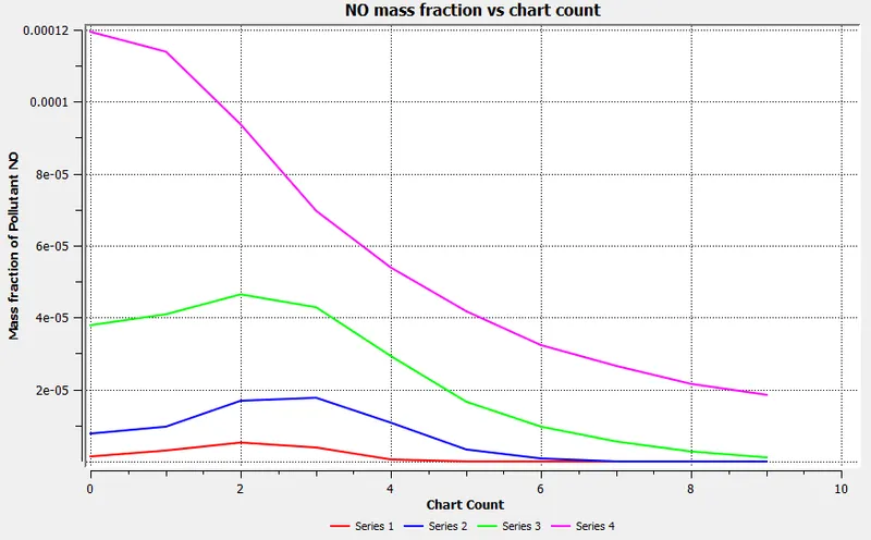
Fig. 35
- The NO concentration decreases as water percentage is increased making the mixture dilute. In an accordance with that the max. temperature decreases.
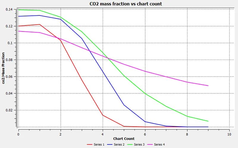
Fig. 36
Fuel inlet : 70% CH4 and 30% H2O
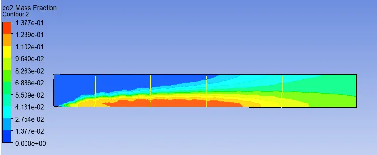
Fig. 37 mass fraction of CO2
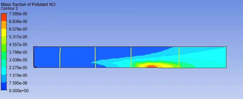
Fig. 38 mass fraction of NO
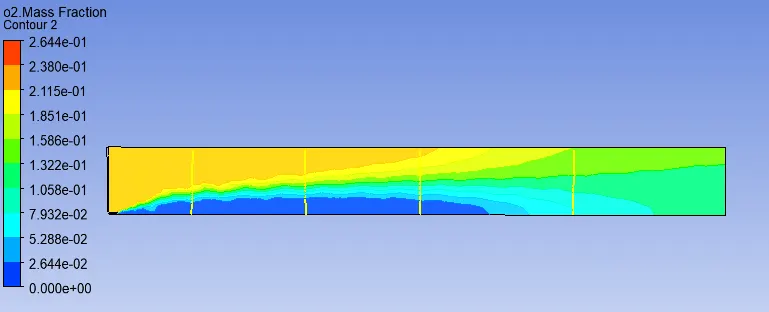
Fig. 39 mass fraction of O2
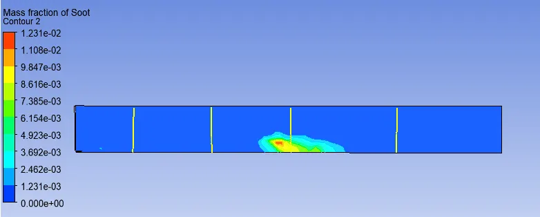
Fig. 40 mass fraction of Soot
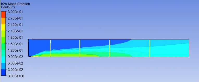
Fig. 41 mass fraction of H2O
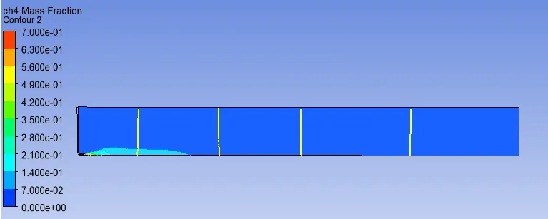
Fig. 42 mass fraction of CH4
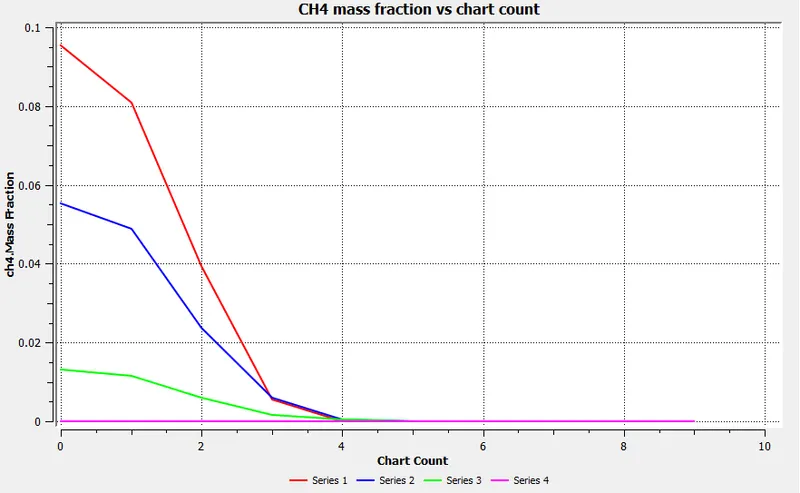
Fig. 43
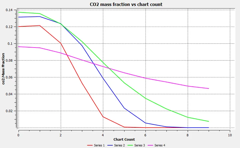
Fig. 44
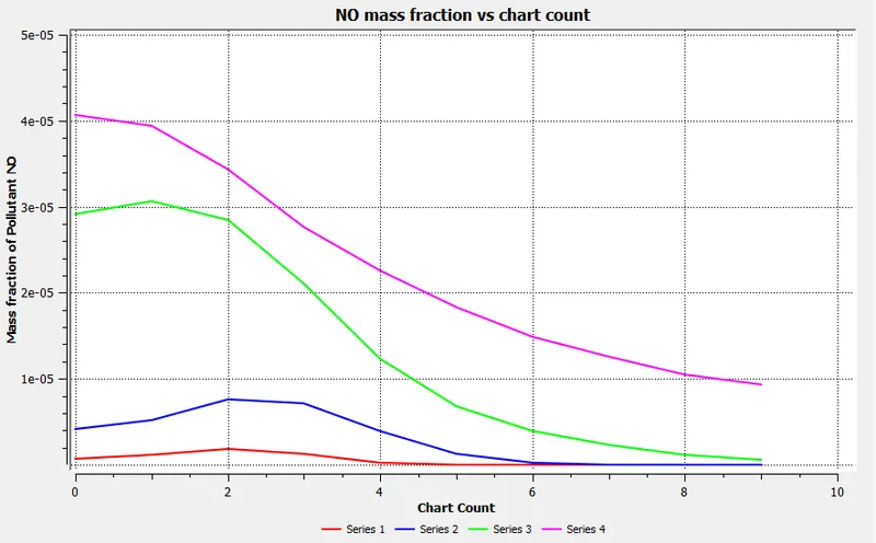
Fig. 45
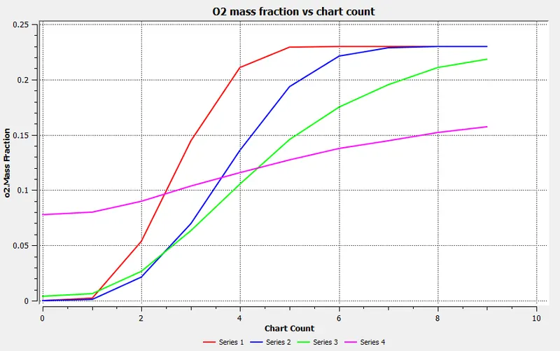
Fig. 46
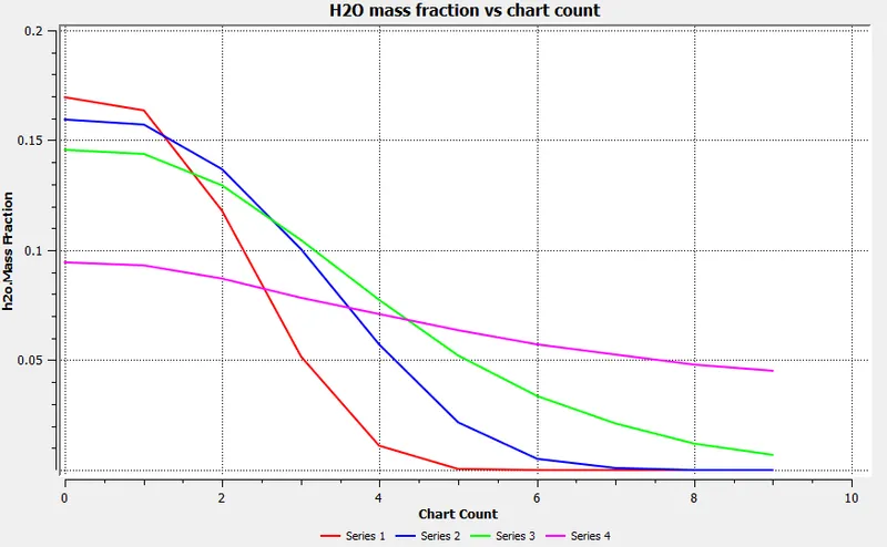
Fig. 47
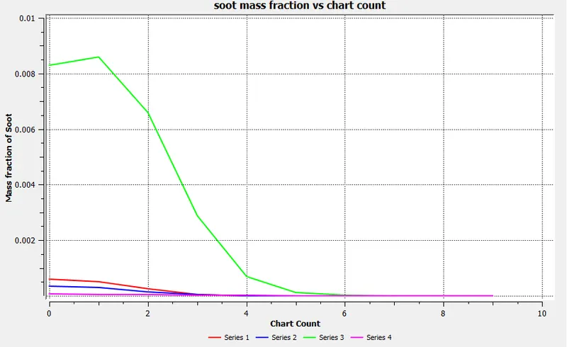
Fig. 48
The purpose of supplying engines with water
- By minimizing temperature peaks, during the combustion process in diesel engines ,hence NOx concentration in exhaust gas can be done by means of supplying water into the reaction zone.
- the emulsion supplied to the reaction zone causes the increase of self ignition delay which affects the flammable mixture becoming more homogenous in the whole volume of the combustion chamber.
- The increased self ignition delay extends the time necessary to spread the injected fuel which results in fewer zones with not enough oxygen.Ultimately decreases the intensity of soot and CO formation.
CONCLUSION
- The emissions of NOx and soot decreases as the water percentage increases.
- The addition of water to the combustor or reaction zone enables it to operate in the low temperature regime.
- More N2O is formed instead of NO as the temperature decreases.
- O2 concentration slightly increases towards the downstream of reaction zone predicts incomplete combustion of fuel.( in case of water addition)
REFERENCE
- fundamentals of combustion process, Sara McAllister
- An overview of system ssupplying water into the combustion chamber of diesel engines to decrease the amount of nitrogen oxides in exhaust gas,leszek Chybowski,Rafal laskowski