Week 10 - Simulating Combustion of Natural Gas.
Simulating Combustion of Natural Gas.
Aim:-
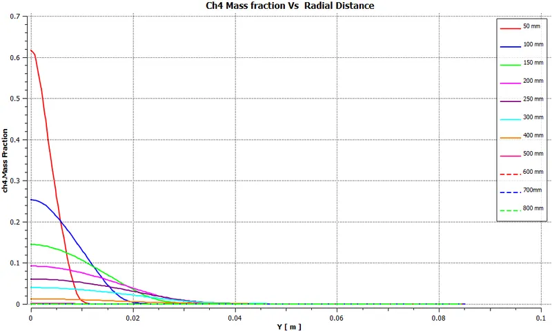
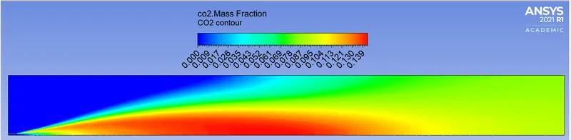
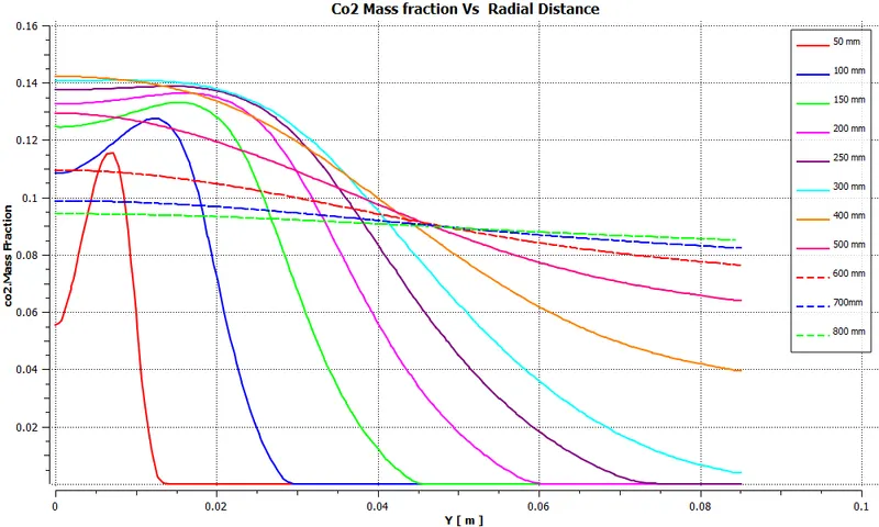
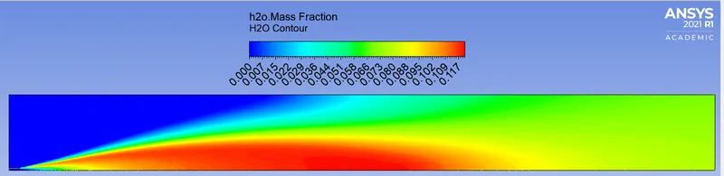
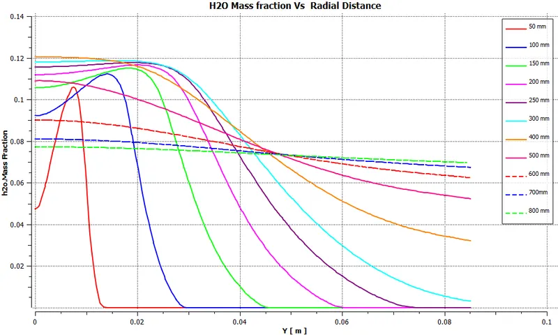
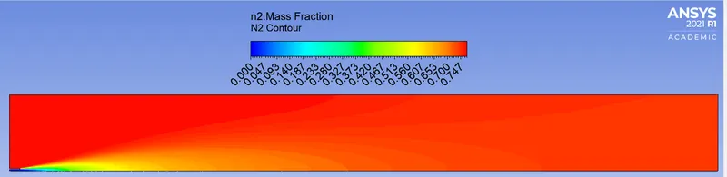
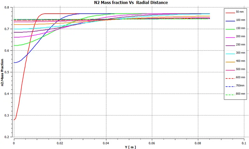
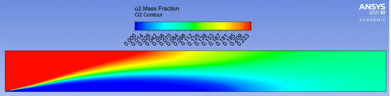
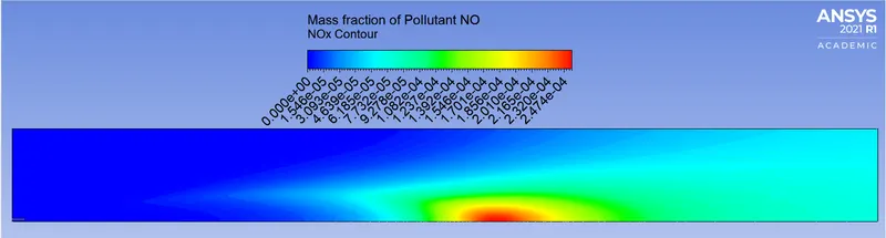
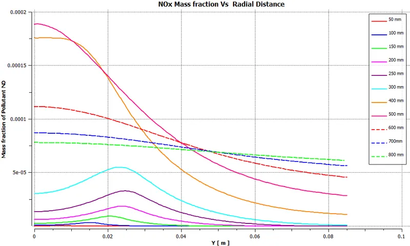
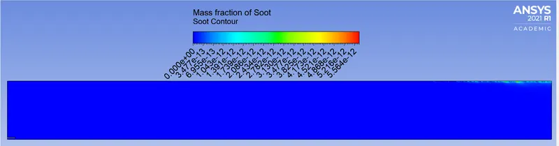
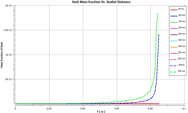
- Perform a combustion simulation on the combustor model and plot the variation of the mass fraction of the different species in the simulation using line probes at different locations of the combustor, need to plot for CO2, H2O, CH4, N2, O2, NOx emissions & Soot formation.
- Nox and soot are getting formed at the outlet of the combustor. Such formation has harmful effects on the environment and humans. The stringent government norms also demand the least formation of Nox and soot and to satisfy those requirements. So, check the effect of adding the water to the fuel. water content in the fuel from 5% to 30% by mole and observe the effect of it on the results.
Eddy Dissipation Model:
- Most fuels are fast burning, and the overall rate of reaction is controlled by turbulent mixing. In non-premixed flames, turbulence slowly convects/mixes fuel and oxidizers into the reaction zones where they burn quickly. In premixed flames, the turbulence slowly convects/mixes cold reactants and hot products into the reaction zones, where the reaction occurs rapidly. In such cases, the combustion is said to be mixing-limited, and the complex and often unknown, chemical kinetic rates can be safely neglected.
----------------------------------------------------------------------------------------------------------------------
Procedure:-
- Geometry preparation
- Meshing
- Setup & Solution
- Results
----------------------------------------------------------------------------------------------------------------------
1. Geometry preparation:
- Open Spaceclaim and import the Combustion Chamber.
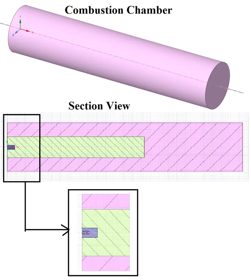
Note:-
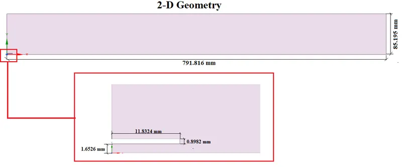
Because of license restrictions and computation power, it is difficult to simulate 3-D combustion using Academic fluent. So, we have to convert this 3-D geometry to a 2-D model.
For 2-D analysis, we are neglecting the change in the radial direction. The solution at any slice is the same.
Converting 3-D geometry to 2-D Geometry.
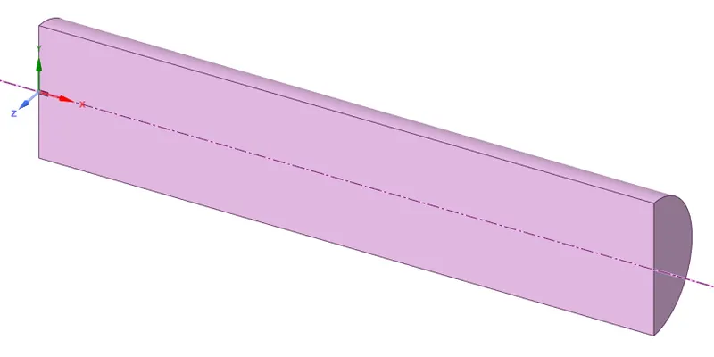
- Split the Combustion chamber using the Split body command.
- Split body
- SPlit-1
- Select the target body (Combustion Chamber)
- Select the cutter(XY plane)
- Select the front region to remove.
- Select the cutter(XY plane)
- Select the target body (Combustion Chamber)
- Split-2
- Repeat the same process by using (XZ plane)
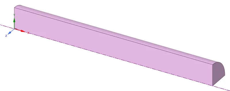
- SPlit-1
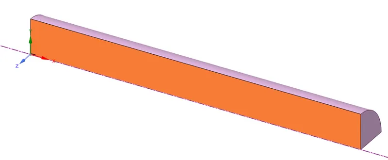
- Now Select the front face and Copy that face.
- Open the New Design file and paste the Copied view.
----------------------------------------------------------------------------------------------------------------------
2. Meshing:
-
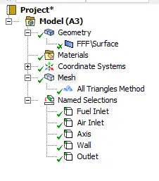
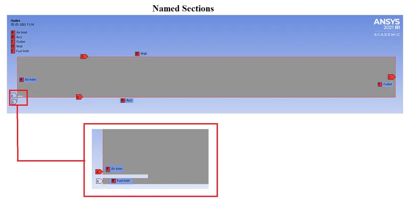
- Creating Named Sections.
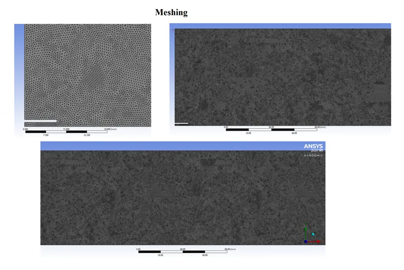
- Mesh generation:
- Method
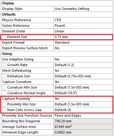
- Triangle-dominated method with element size = 0.75 mm
- Capture Proximity
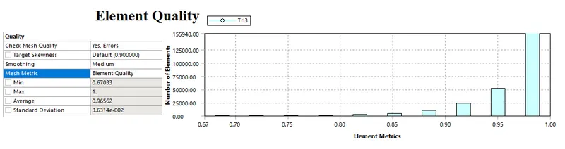
- Quality:
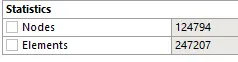
- Statistics:
- Method
3. Setup & Solution:-
- Double Precision, Solve processers = 4.
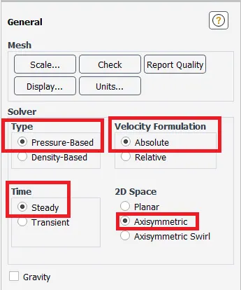
- Solver
- Type = Pressure Based
- Velocity Formulation = Absolute.
- Time= Steady
- 2D Space = Axisymmetric
- Time= Steady
- Velocity Formulation = Absolute.
- Type = Pressure Based
- Energy Equation
- on
- Viscous model
- k-epsilon (2 eqn)
- Standard
- Standard Wall Treatment
- Standard
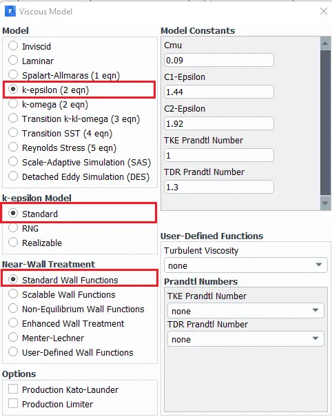
- k-epsilon (2 eqn)
- Species Modelling:
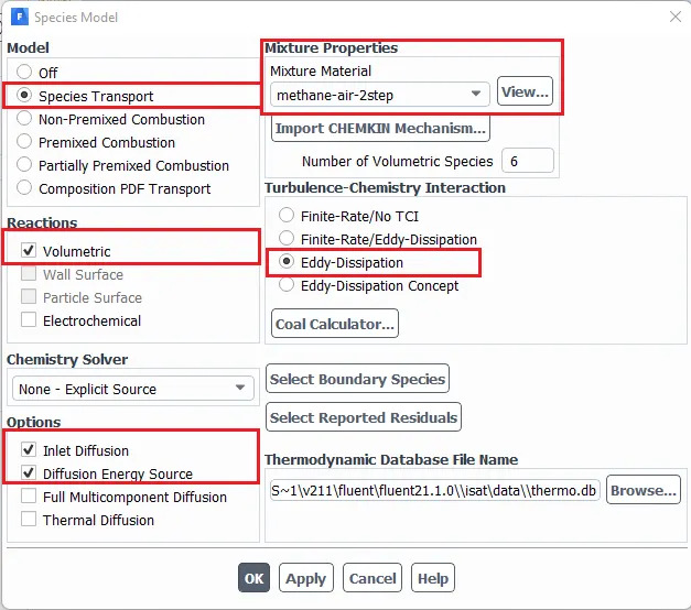
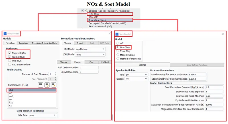
- Pollutants NOx and Soot modeling:
- Boundary conditions:-
-
Type Momentum & Thermal Air Inlet Velocity inlet 0.5 m/s & 300 K Fuel Inlet Velocity inlet 80 m/s & 300 K Outlet Pressure Outlet Guage Total pressure = 0 [Pa] Wall Motion Shear Condition Wall Stationary Wall No-slip 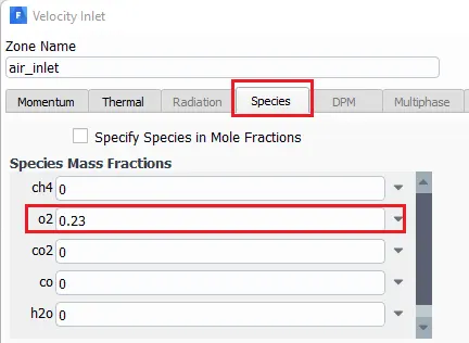
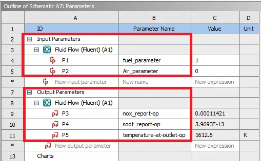
- Input Parameterizing the Fuel Mass fraction
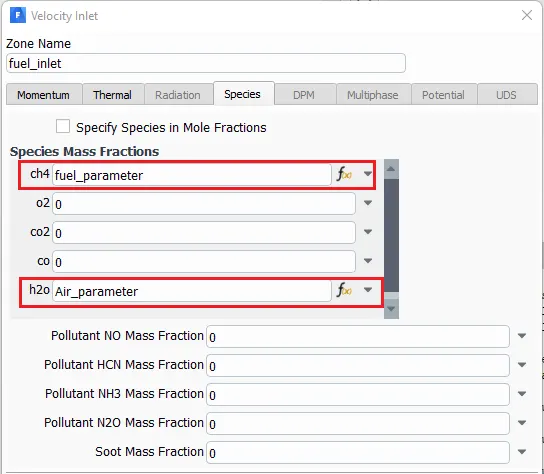
-
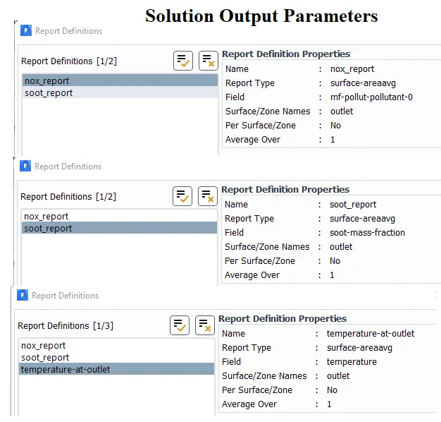
- Creating Report files for Solution Output parameters at Outlet.
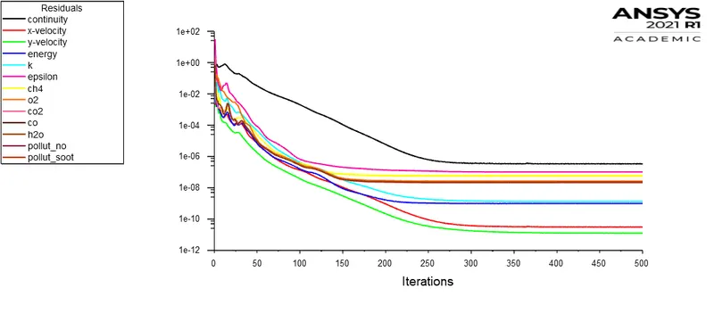
- Residual Monitors:
- Uncheck the convergence for all equations.
- Initialization:
- Hybrid Initialization
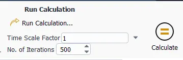
- Run Calculations:-
- Steady-State Simulation
- Steady-State Simulation
----------------------------------------------------------------------------------------------------------------------
4. Parameters & Design Point setting:-
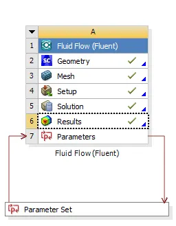
- Parameters:-
- Design Points Calculation:
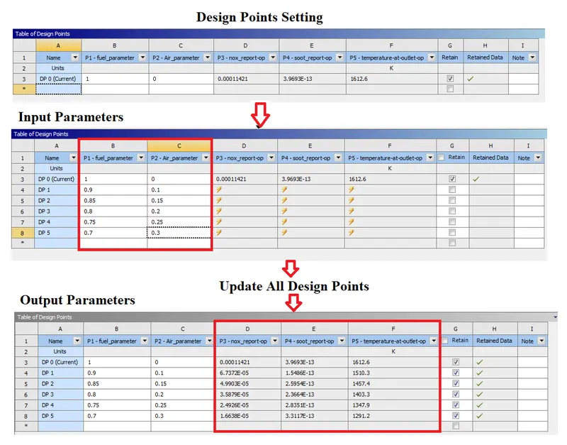
- Parametric study on the Natural Gas combustion simulation by setting the Fuel & Water Mass fraction as input parameter.
-
Design Point
CH4 Mass Fraction H20 Mass Fraction
0 1 0 1 0.9 0.1 2 0.85 0.15 3 0.8 0.2 4 0.75 0.25 5 0.7 0.3
-
- Parametric study on the Natural Gas combustion simulation by setting the Fuel & Water Mass fraction as input parameter.
- Design point setting:-
- Add Design points by entering magnitudes in the input section.
- Enable the retain option so that each saves individually.
----------------------------------------------------------------------------------------------------------------------
4. Results:-
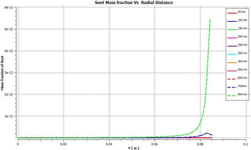
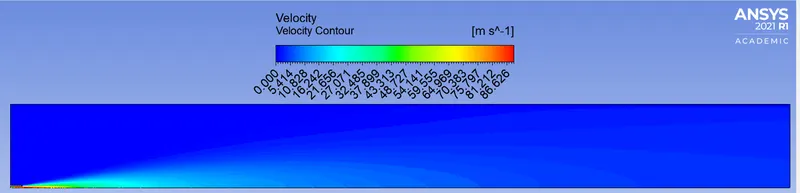
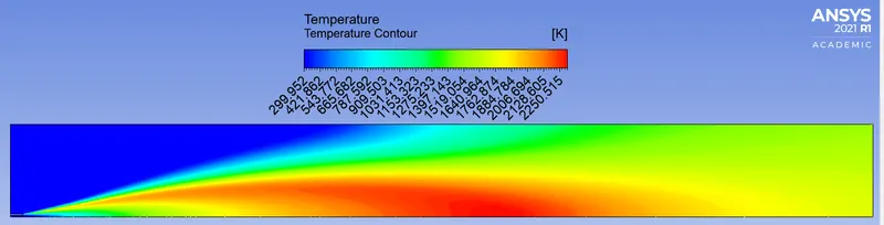
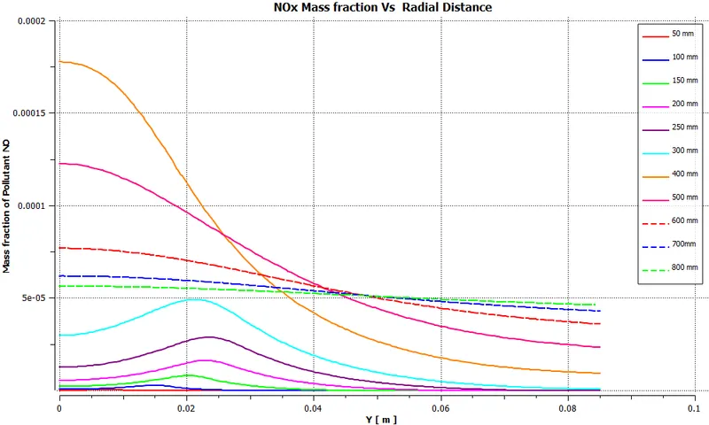
line probes at different locations

Case 1
-
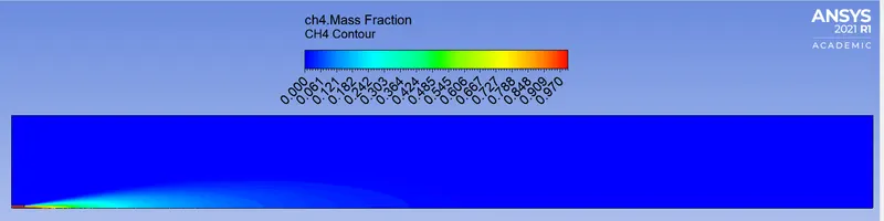
Design Point = 0 Ch4 Mass Fraction = 1
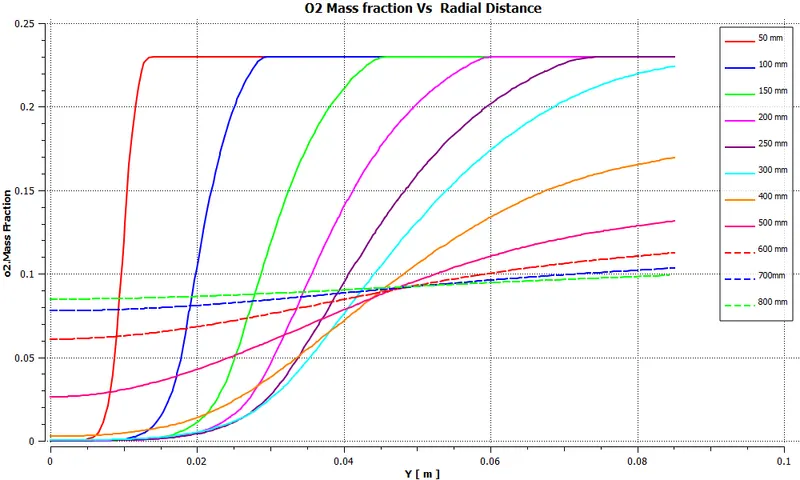
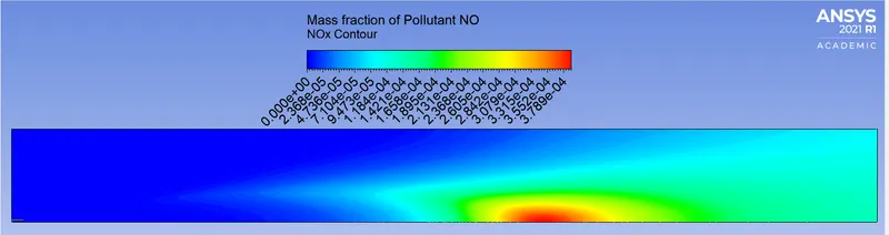
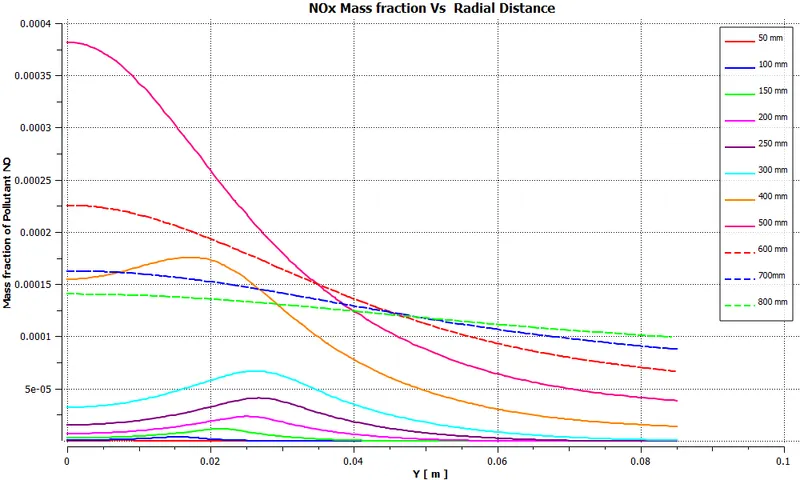
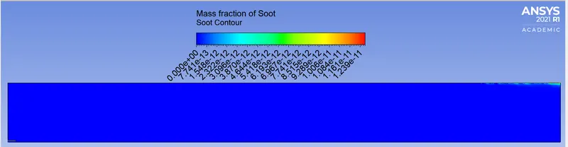
----------------------------------------------------------------------------------------------------------------------
Case 2:-
-
Design Point = 1 Ch4 Mass Fraction = 0.9 H2O Mass fraction = 0.1 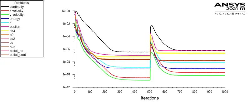
- ----------------------------------------------------------------------------------------------------------------------
-
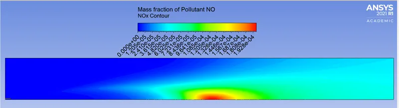
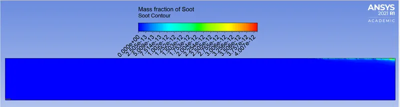
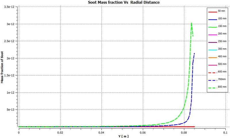
Design Point = 2 Ch4 Mass Fraction = 0.85 H2O Mass fraction = 0.15 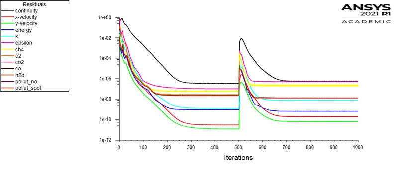
- ----------------------------------------------------------------------------------------------------------------------
-
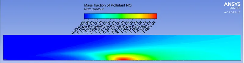
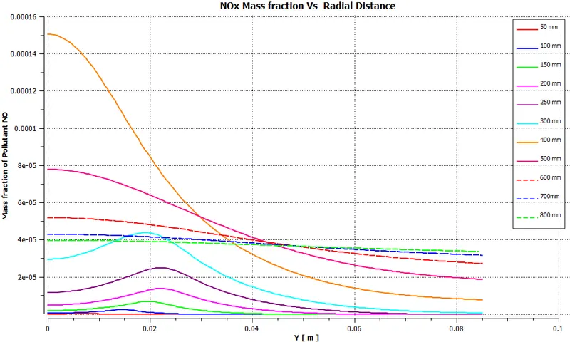
Design Point = 3 Ch4 Mass Fraction = 0.85 H2O Mass fraction = 0.15 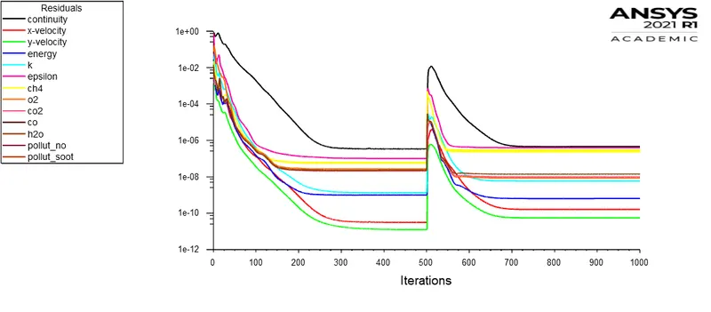
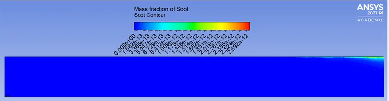
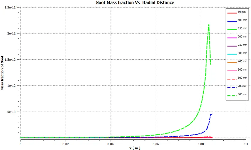
- ----------------------------------------------------------------------------------------------------------------------
-
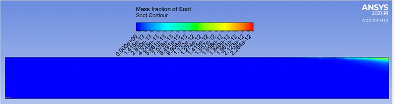
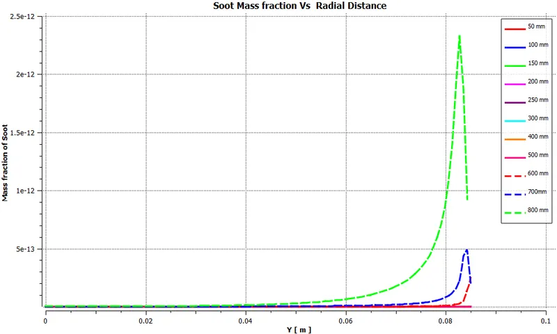
Design Point = 4 Ch4 Mass Fraction = 0.75 H2O Mass fraction = 0.25 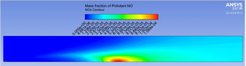
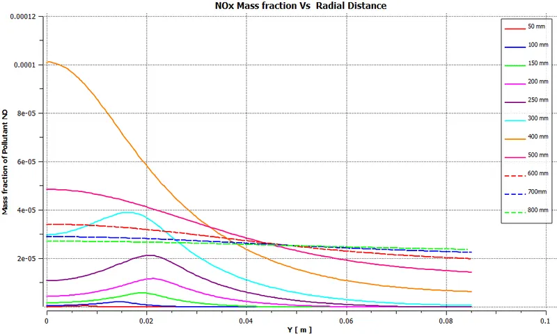
- ----------------------------------------------------------------------------------------------------------------------
-
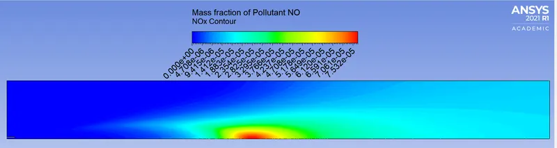
Design Point = 5 Ch4 Mass Fraction = 0.7 H2O Mass fraction = 0.3 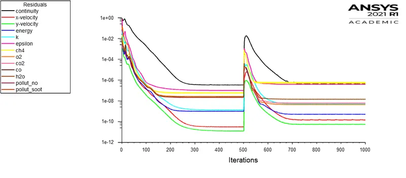
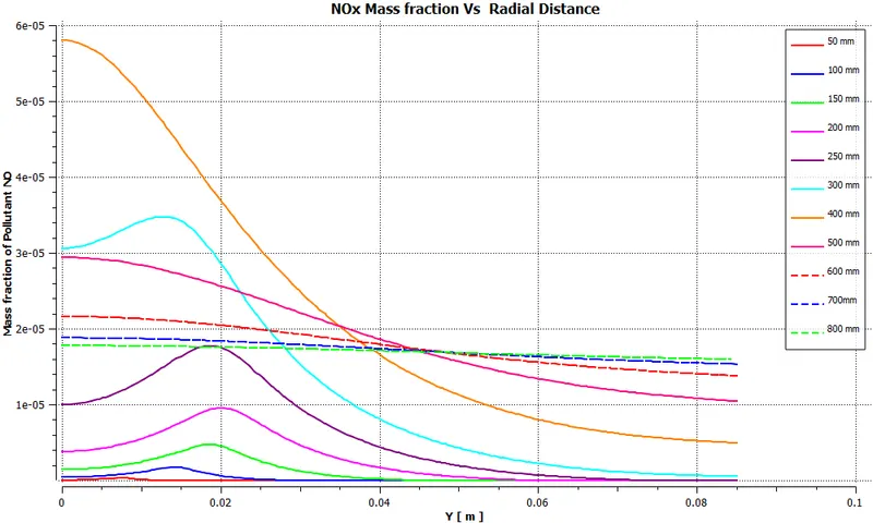
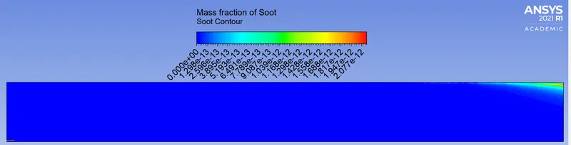
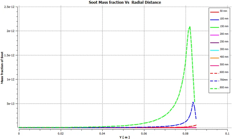
- ----------------------------------------------------------------------------------------------------------------------
----------------------------------------------------------------------------------------------------------------------
Result Table:-
| Design Point | CH4 Mass Fraction | H20 Mass Fraction | Nox | Soot | Outlet Temperature K |
| 0 | 1 | 0 | 0.000114 | 3.97E-13 | 1612.617 |
| 1 | 0.9 | 0.1 | 6.74E-05 | 1.55E-13 | 1510.27 |
| 2 | 0.85 | 0.15 | 4.99E-05 | 2.60E-13 | 1457.381 |
| 3 | 0.8 | 0.2 | 3.59E-05 | 2.37E-13 | 1403.283 |
| 4 | 0.75 | 0.25 | 2.49E-05 | 2.84E-13 | 1347.918 |
| 5 | 0.7 | 0.3 | 1.66E-05 | 3.31E-13 | 1291.222 |
----------------------------------------------------------------------------------------------------------------------
Plots:-
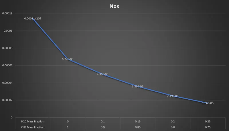
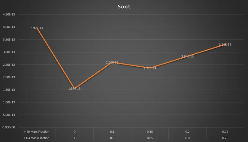
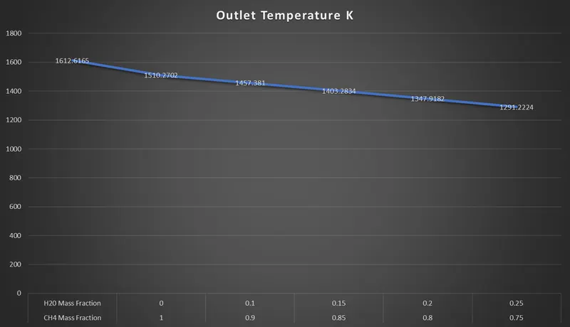
----------------------------------------------------------------------------------------------------------------------
Conclusions:-
- From the graph, we can observe that Adding water molecules to the Fuel from 5% to 30% by mole reduced the amount of Nox Emission.
- By adding H2O molecules amount of soot emitted decreased initially for 10% water after that Soot emission Increased.
- Adding water Leads to a decrease in the outlet temperature.