Week 10 - Simulating Combustion of Natural Gas.
Simulating Combustion of Natural Gas
AIM:-
To Perform a combustion simulation on the combustor model.
OBJECTIVE:-
- To plot the variation of the mass fraction of the different species’ in the simulation using line probes at different locations of the combustor an to plot for CO2, H2O, CH4, N2, O2, NOx emissions & Soot formation.
- To add the water content in the fuel from 5% to 30% by mole and to observe the effect of it on the results.
INTRODUCTION:-
Combustion, is a high-temperature exothermic redox chemical reaction between a fuel (the reductant) and an oxidant, usually atmospheric oxygen, that produces oxidized, often gaseous products, in a mixture termed as smoke. Combustion does not always result in fire, because a flame is only visible when substances undergoing combustion vapourise, but when it does, a flame is a characteristic indicator of the reaction. The rate or speed at which the reactants combine is high, in part because of the nature of the chemical reaction itself and in part because more energy is generated than can escape into the surrounding medium, with the result that the temperature of the reactants is raised to accelerate the reaction even more.
A simple example can be seen in the combustion of hydrogen and oxygen into water vapor, a reaction commonly used to fuel rocket engines. This reaction releases 242 kJ/mol of heat and reduces the enthalpy accordingly (at constant temperature and pressure):
2H2(g) + O2(g) → 2H2O(g)
Combustion of an organic fuel in air is always exothermic because the double bond in O2 is much weaker than other double bonds or pairs of single bonds, and therefore the formation of the stronger bonds in the combustion products CO2 and H2O results in the release of energy. The bond energies in the fuel play only a minor role, since they are similar to those in the combustion products; e.g., the sum of the bond energies of CH4 is nearly the same as that of CO2.
Complete combustion --> In complete combustion, the reactant burns in oxygen and produces a limited number of products. When a hydrocarbon burns in oxygen, the reaction will primarily yield carbon dioxide and water. When elements are burned, the products are primarily the most common oxides. Carbon will yield carbon dioxide, sulfur will yield sulfur dioxide, and iron will yield iron(III) oxide. Nitrogen is not considered to be a combustible substance when oxygen is the oxidant. Still, small amounts of various nitrogen oxides (commonly designated NOx species) form when the air is the oxidative.
Combustion is not necessarily favorable to the maximum degree of oxidation, and it can be temperature-dependent. For example, sulfur trioxide is not produced quantitatively by the combustion of sulfur. NOx species appear in significant amounts above about 2,800 °F (1,540 °C), and more is produced at higher temperatures. The amount of NOx is also a function of oxygen excess.
Incomplete combustion --> Incomplete combustion will occur when there is not enough oxygen to allow the fuel to react completely to produce carbon dioxide and water. It also happens when the combustion is quenched by a heat sink, such as a solid surface or flame trap. As is the case with complete combustion, water is produced by incomplete combustion; however, carbon, carbon monoxide, and hydroxide are produced instead of carbon dioxide.
For most fuels, such as diesel oil, coal, or wood, pyrolysis occurs before combustion. In incomplete combustion, products of pyrolysis remain unburnt and contaminate the smoke with noxious particulate matter and gases. Partially oxidized compounds are also a concern; partial oxidation of ethanol can produce harmful acetaldehyde, and carbon can produce toxic carbon monoxide.
Geometry:-
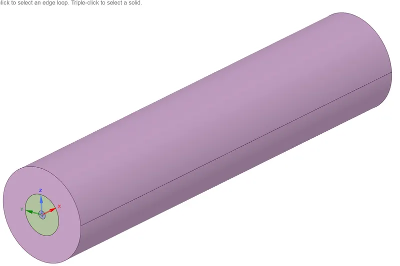
- The below figure.1 is the geometry of a combustor we need to convert it from 3D to 2D, because it is a 3D model it requires lot of time and powerful computer.
- Using split body option we need to split the body as shown in figure.2.
|
Figure.1 |
Figure.2 |
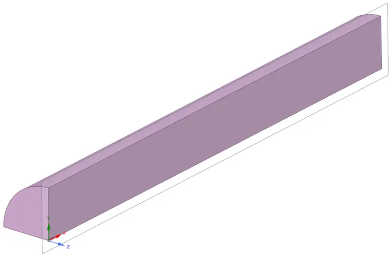
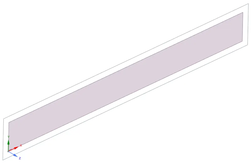
- After spliting the body we need to copy the surface which is in XY plane and paste it in new design as shown in below figure.
 |
Meshing:-
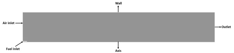
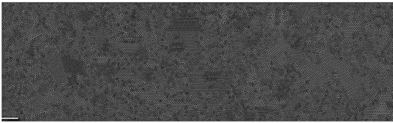
Here we need to name the boundaries using named selection option as inlet_fuel, inlet_air, axis, wall and outlet. Then we need to generate mesh as shown in below figure.
- Element size --> 1 mm
- Mesh method --> All triangle method
- Number of Nodes --> 72868
- Number of Elements --> 143936
- Proximity min size --> 0.5
- Num cells across gap --> 3
 |
 |
 |
Setup :-
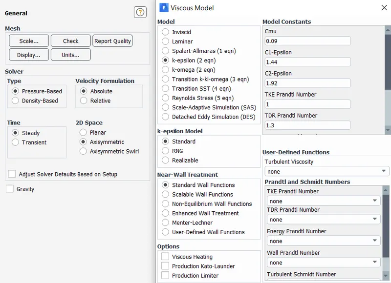
General setings:
- Analysis type --> Steady state
- Solver --> Pressure based solver
- 2D space --> Axis symmetric
Energy mode: On
Viscous model:
- Model --> K-epsilon
- K-epsilon model --> Standard
- Near wall treatment --> Strandard wall functions
 |
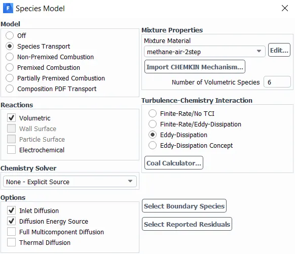
Species model:
- Model --> Species transport (It enables calculation of multi species transport)
- Reactions --> Volumetric
- Options --> Inlet diffusion & Diffusion energy source
- Mixture material --> Methane-air-2step
- Turbulent chemistry interactions --> Eddy-Dissipation
 |
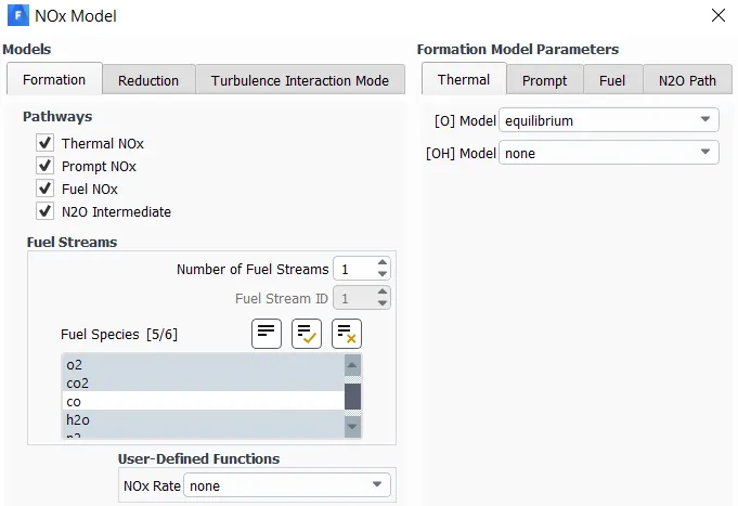
Species transport reaction:
1) NOx
- Pathways --> Thermal NOx, Prompt NOx, Fuel NOx, N2O intermediate
- Fuel species --> CH4, H2O, O2, N2 & CO2
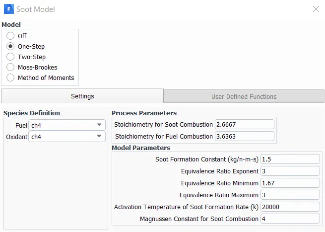
2) Soot
- Model --> One-step
 |
 |
Boundary conditions:
1) Air inlet
- Velocity magnitude --> 0.5m/s
- Temperature --> 300K
- Species mass fraction --> O2 = 0.23 (It remains same for all cases)
2) Fuel inlet
- Velocity magnitude --> 80 m/s
- Temperature --> 300K
- Species mass fraction --> CH4 = 1 (It changes for different cases and from 2nd case adding H20 to it from 5% to 30%)
3) Wall
- Wall motion --> Stationary wall
- Shear condition --> No slip
- Temperature --> 300K
4) Outlet
- Type --> Pressure outlet
- Guage total pressure --> 0 Pa
- Back flow total temperature --> 300K
Solution initializtion:
- After creating species model and boundary condition we need to initialize the solution using Hybrid initialization.
RESULTS:-
Part 1:
Case 1 -->
- Air inlet - Velocity magnitude --> 0.5m/s , Temperature --> 300K, Species mass fraction --> O2 = 0.23
- Fuel inlet - Velocity magnitude --> 80 m/s, Temperature --> 300K, Species mass fraction --> CH4 = 1
|
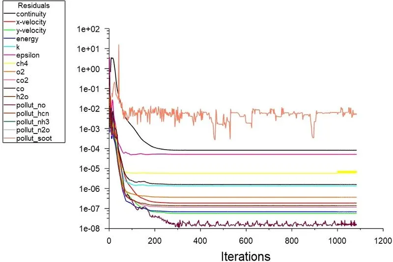
Residuals plot -
|
|
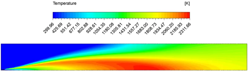
Temperature contour plot -
|
|
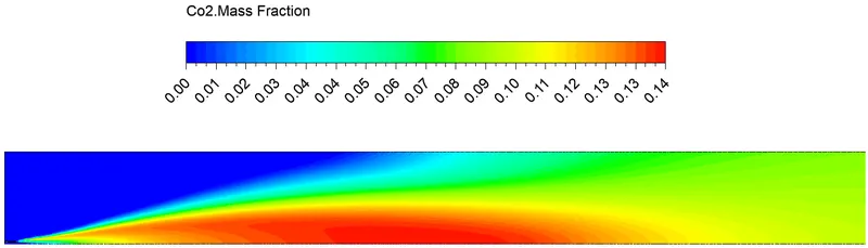
Contour of Co2 mass fraction -
|
|
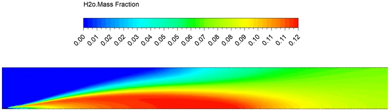
Contour of H2o mass fraction -
|
|
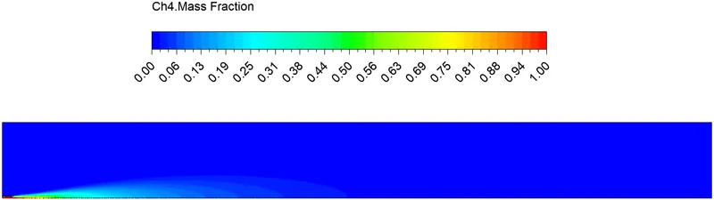
Contour of Ch4 mass fraction -
|
|
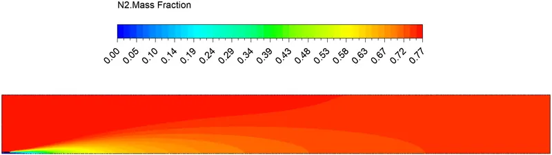
Contour of N2 mass fraction -
|
|
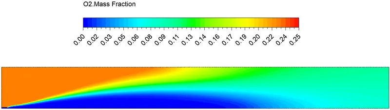
Contour of O2 mass fraction -
|
|
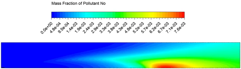
Contour of Pollutant No mass fraction -
|
|
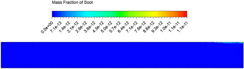
Contour of Soot mass fraction -
|
Line Probe:-
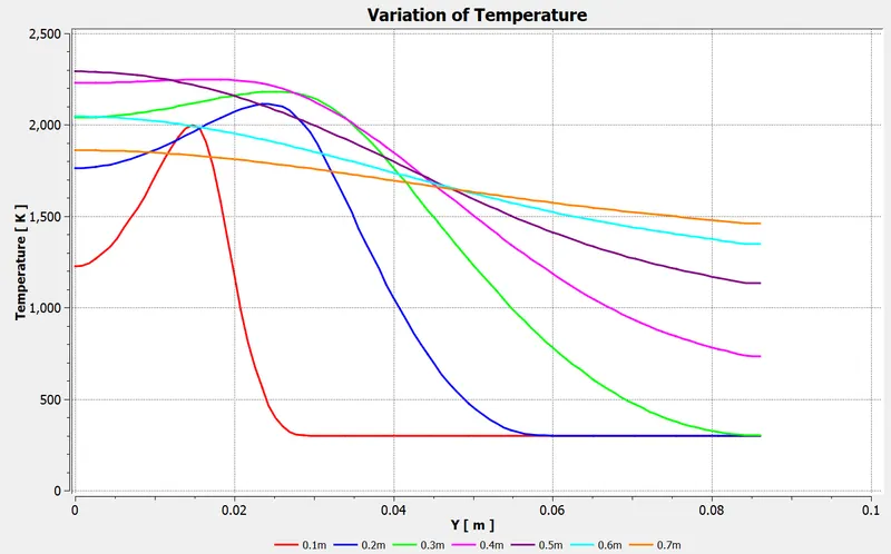
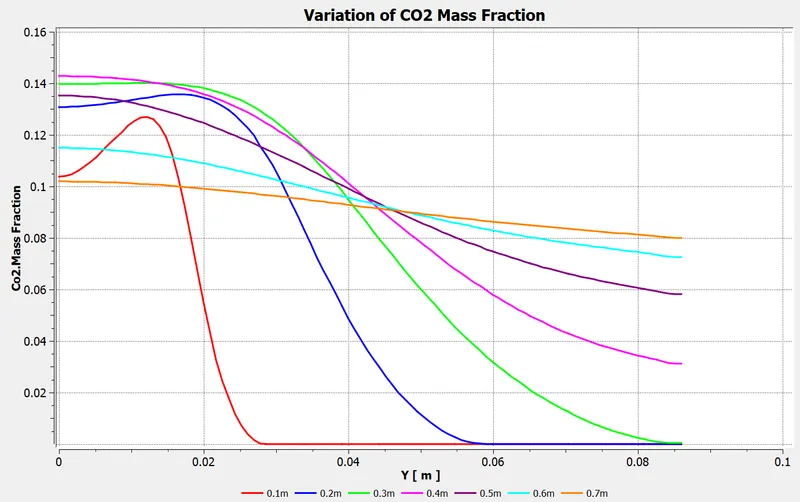
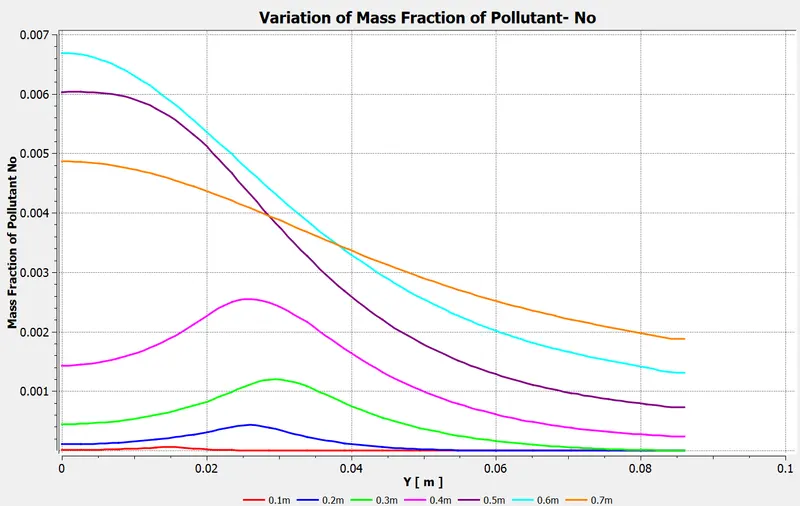
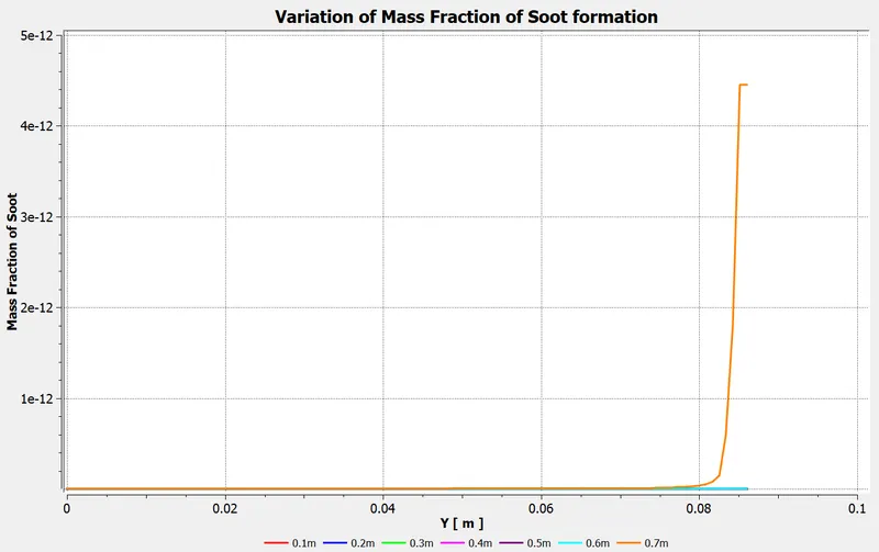
- Below charts are the variation of temperature and mass fraction of different species at different locations on combustor.
- By creating a line probes, we can plot the variation of mass fraction at different locations.
- For that we have created 7 line probes at different locations in a combustor as shown in below figure.
- Lines are created in a such a way that different between 2 line is 0.1m
 |
|
Variation of Temperature -
|
|
Variation of Mass fraction of CO2 -
|
|
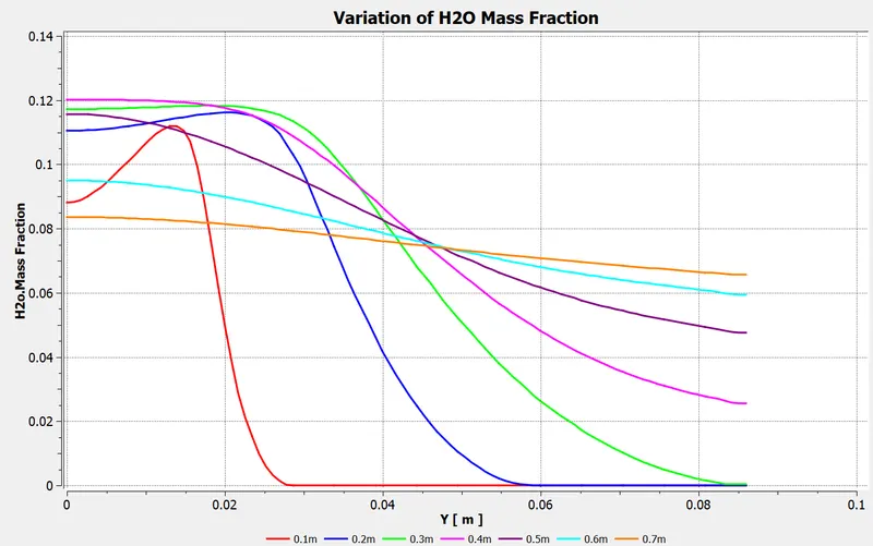
Variation of Mass fraction of H2o -
|
|
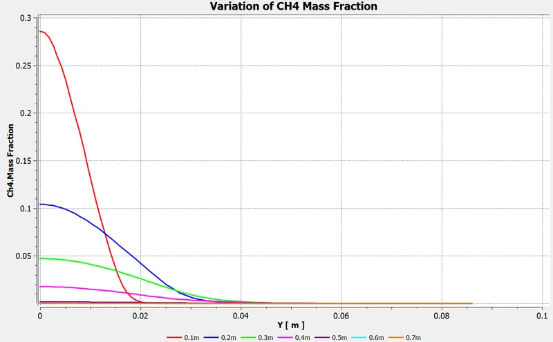
Variation of Mass fraction of CH4 -
|
|
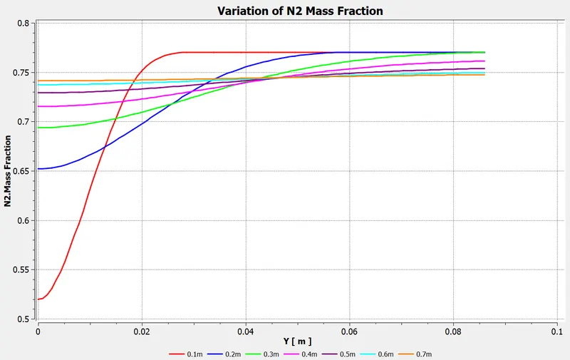
Variation of Mass fraction of N2 -
|
|
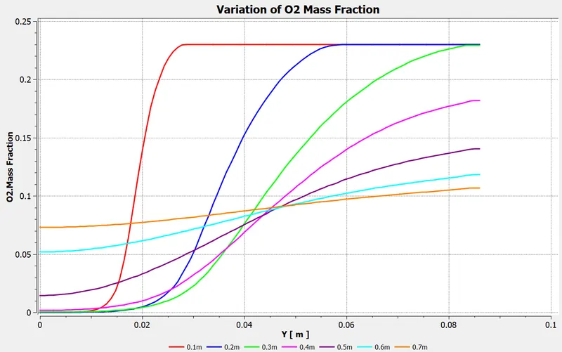
Variation of Mass fraction of O2 -
|
|
Variation of Mass fraction of Pollutant NO -
|
|
Variation of Mass fraction of Soot -
|
Comparision of mass fraction of different species in Part 1
| Species | Mass fraction |
| CO2 | 0.14 |
| H2O | 0.12 |
| CH4 | 1 |
| N2 | 0.77 |
| O2 | 0.25 |
| No | `7.6*10^-3` |
| Soot | `1.1*10^-11` |
- From the above chart we can see that mass fraction of O2 increases from 0 to 0.25 as gone higher along the y-axis but after some distance that is after 0.3 it decreases.
- From this we can clearly say that most of the O2 are burnt.
- Also, we can see that fuel inlet is at origin, the mass fraction of CH4 decreases from 1 to 0 along the y axis and far from inlet it is very low but it is not completely burnt. In real some unburnt carbon particles remains.
- Because of the incomplete combustion soot and fly ash is generated.
- CO2 and H20 both mass is highest and increases at the centre and it gradually decreaces as temperature becomes uniform.
=========================================================================================
Part 2:
Case 1 --> 5% H20
- Air inlet - Velocity magnitude --> 0.5m/s , Temperature --> 300K, Species mass fraction --> O2 = 0.23
- Fuel inlet - Velocity magnitude --> 80 m/s, Temperature --> 300K, Species mass fraction --> CH4 = 0.95 , H20 = 0.05
|
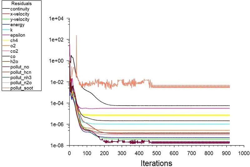
Residuals plot -
|
|
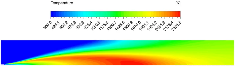
Temperature contour plot -
|
|
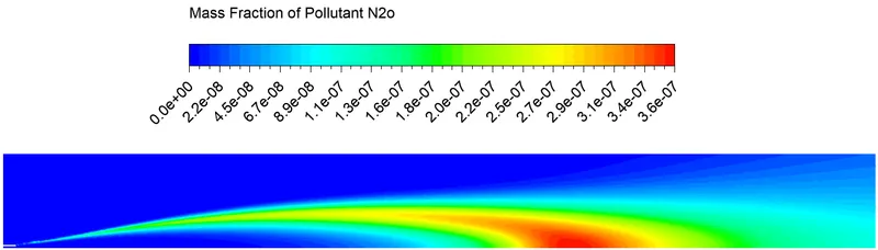
Contour of Pollutant N2o mass fraction -
|
|
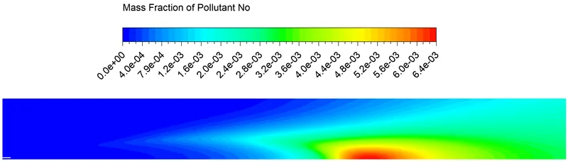
Contour of Pollutant No mass fraction -
|
|
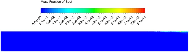
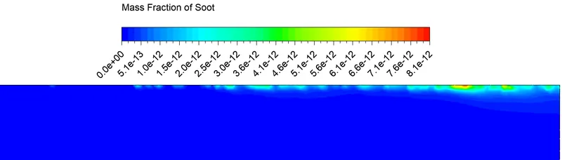
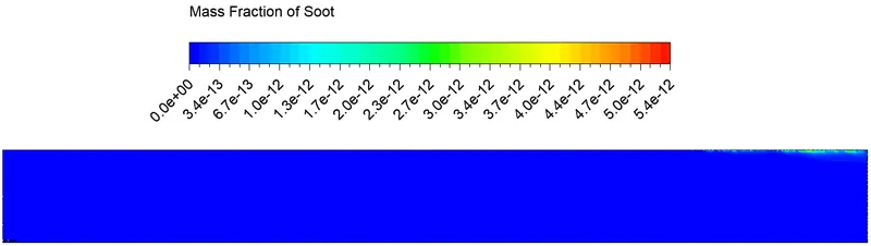
Contour of Soot mass fraction -
|
|
Variation of Temperature - 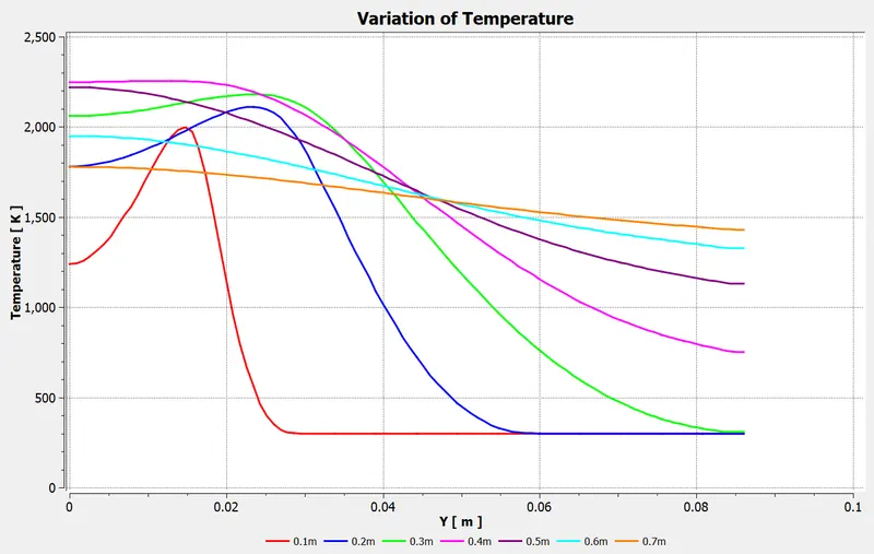 |
|
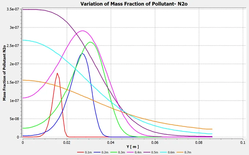
Variation of Mass fraction of Pollutant N2o -
|
|
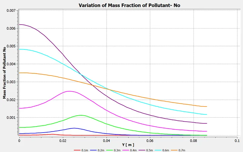
Variation of Mass fraction of Pollutant No -
|
|
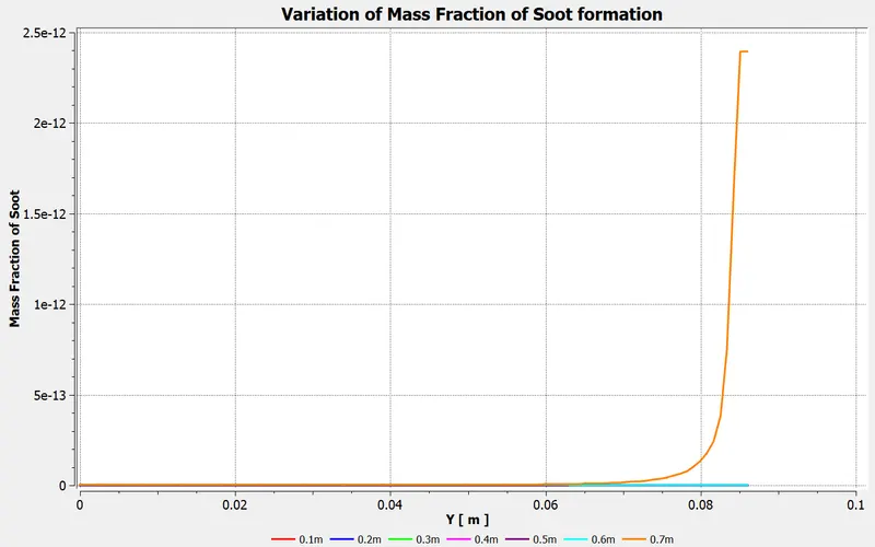
Variation of Mass fraction of Soot -
|
_______________________________________________________________________________________________________________
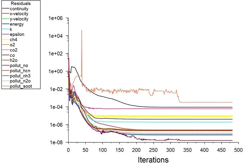
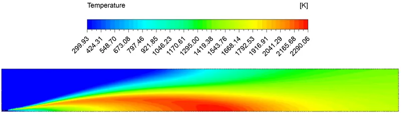
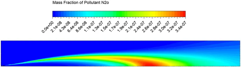
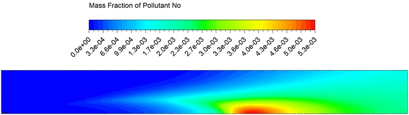
Case 2 --> 10% H20
- Air inlet - Velocity magnitude --> 0.5m/s , Temperature --> 300K, Species mass fraction --> O2 = 0.23
- Fuel inlet - Velocity magnitude --> 80 m/s, Temperature --> 300K, Species mass fraction --> CH4 = 0.9 , H20 = 0.1
|
Residuals plot -
|
|
Temperature contour plot -
|
|
Contour of Pollutant N2o mass fraction -
|
|
Contour of Pollutant No mass fraction -
|
|
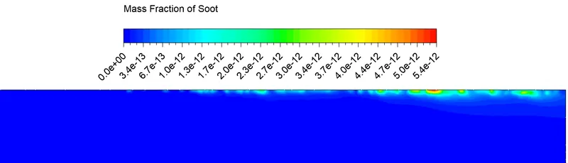
Contour of Soot mass fraction -
|
|
Variation of Temperature - 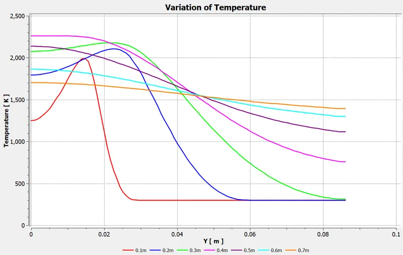 |
|
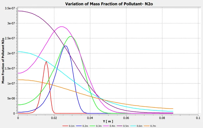
Variation of Mass fraction of Pollutant N2o -
|
|
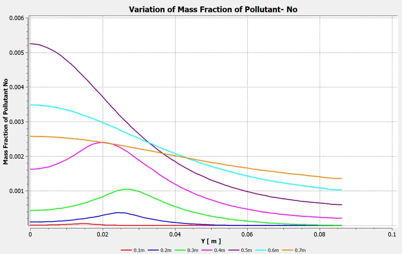
Variation of Mass fraction of Pollutant No -
|
|
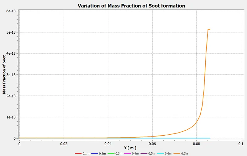
Variation of Mass fraction of Soot -
|
_______________________________________________________________________________________________________________
Case 3 --> 20% H20
- Air inlet - Velocity magnitude --> 0.5m/s , Temperature --> 300K, Species mass fraction --> O2 = 0.23
- Fuel inlet - Velocity magnitude --> 80 m/s, Temperature --> 300K, Species mass fraction --> CH4 = 0.8 , H20 = 0.2
|
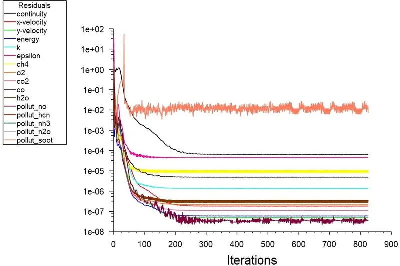
Residuals plot -
|
|
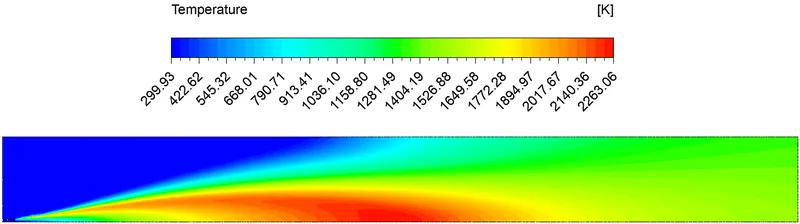
Temperature contour plot -
|
|
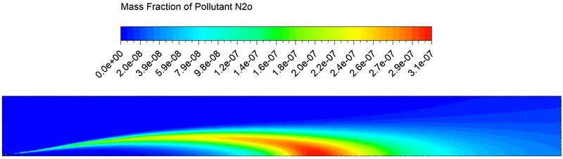
Contour of Pollutant N2o mass fraction -
|
|
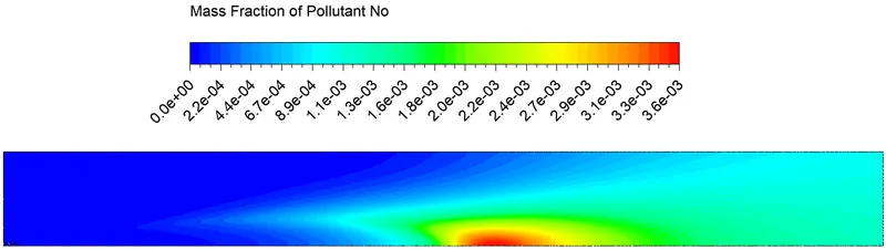
Contour of Pollutant No mass fraction -
|
|
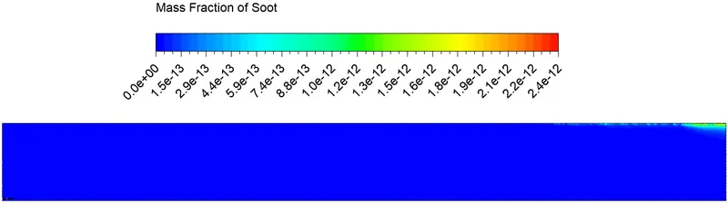
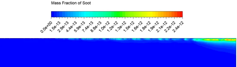
Contour of Soot mass fraction -
|
|
Variation of Temperature - 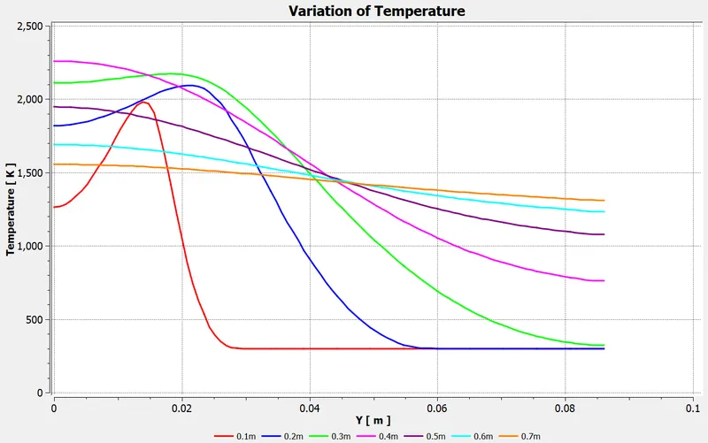 |
|
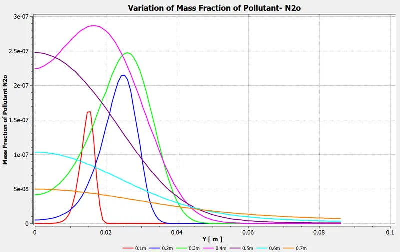
Variation of Mass fraction of Pollutant N2o -
|
|
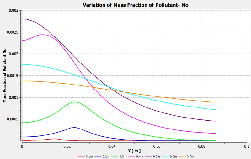
Variation of Mass fraction of Pollutant No -
|
|
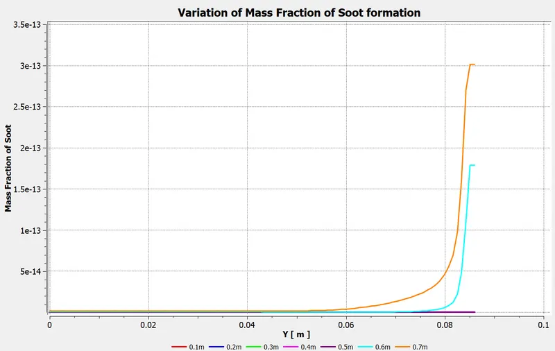
Variation of Mass fraction of Soot -
|
_______________________________________________________________________________________________________________
Case 4 --> 30% H20
- Air inlet - Velocity magnitude --> 0.5m/s , Temperature --> 300K, Species mass fraction --> O2 = 0.23
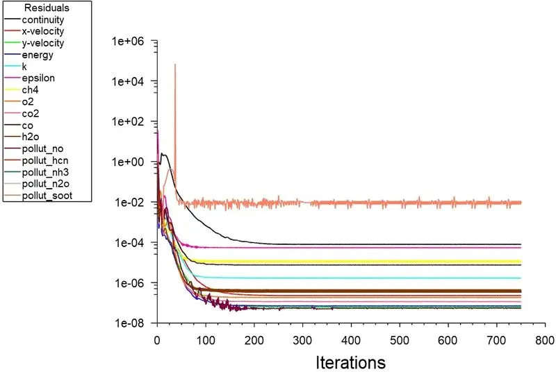
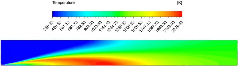
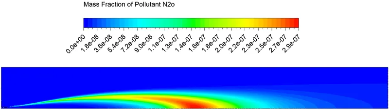
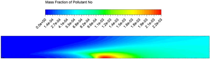
- Fuel inlet - Velocity magnitude --> 80 m/s, Temperature --> 300K, Species mass fraction --> CH4 = 0.7 , H20 = 0.3
|
Residuals plot -
|
|
Temperature contour plot -
|
|
Contour of Pollutant N2o mass fraction -
|
|
Contour of Pollutant No mass fraction -
|
|
Contour of Soot mass fraction -
|
|
Variation of Temperature - 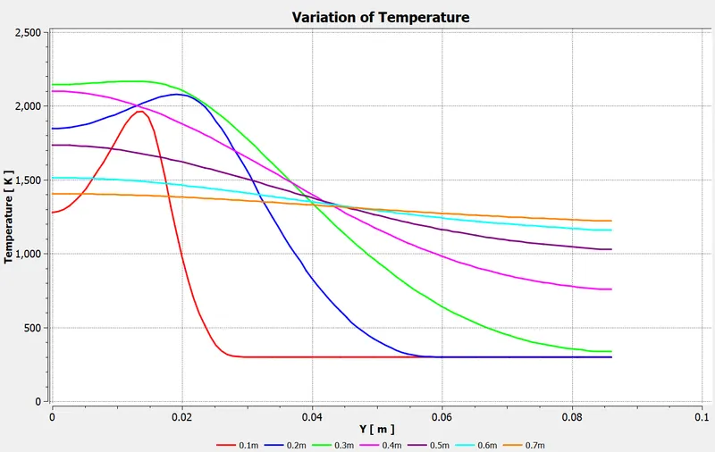 |
|
Variation of Mass fraction of Pollutant N2o -
|
|
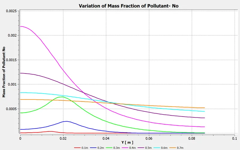
Variation of Mass fraction of Pollutant No -
|
|
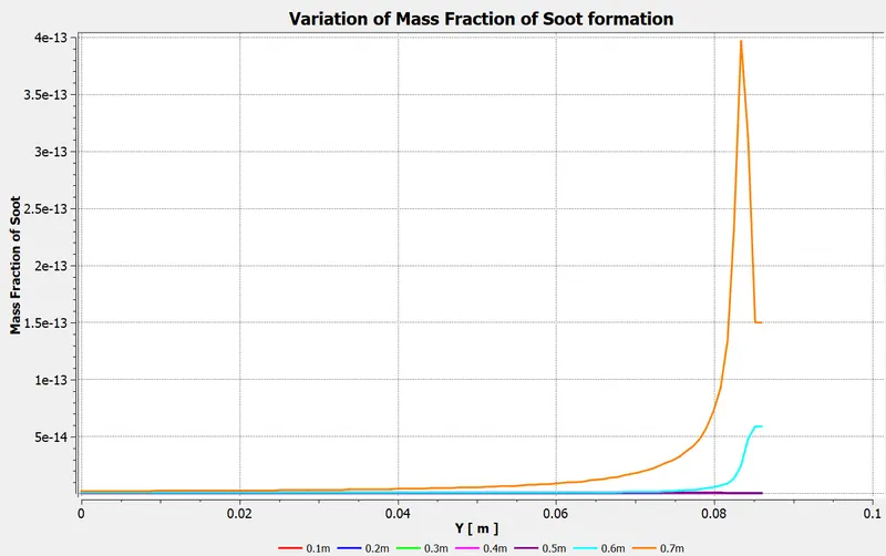
Variation of Mass fraction of Soot -
|
Comparision of Temperature and Mass fraction of NOx and Soot in part 2
| Case | Temperature (K) | Mass fraction of N2o | Mass fraction of No | Mass fraction of Soot |
| Case 1 | 2301.5 | 3.6e-07 | 6.4e-03 | 8.1e-12 |
| Case 2 | 2290.1 | 3.4e-07 | 5.3e-03 | 5.4e-12 |
| Case 3 | 2263.1 | 3.1e-07 | 3.6e-03 | 2.4e-12 |
| Case 4 | 2229.53 | 2.9e-07 | 2.2e-03 | 1.3e-12 |
- From the above results and charts we can clearly see that teemperature decreases from case 1 to case 4 that is from 5% to 30%.
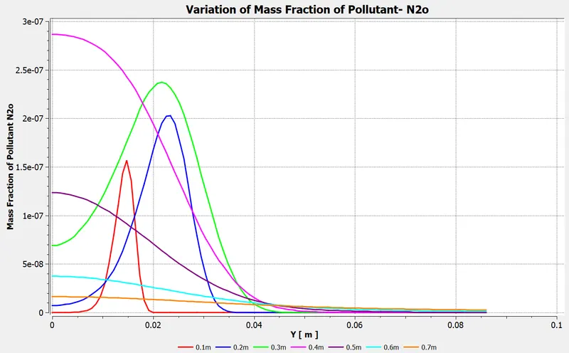
- Also, there is a decrease in NOx emission as we add the water from 5% to 30%.
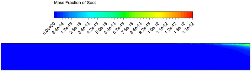
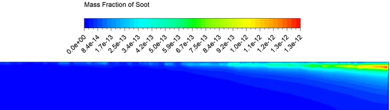
- From which there is a significant decrease in the formation of Soot by adding water from 5% to 30%.
- From the above results we can clearly say that adding water to the fuel helps in decreasing NOx and Soot formation.