Week 10: Proportional Valve simulation
Title: Proportional valve simulation
Aim: To set up case for following cases for following cases in converge.
- 3 cases without Adaptive Mesh Refinement (AMR)
- Lift = 3 mm
- Lift = 4 mm
- Lift = 5 mm
- 3 cases with Adaptive Mesh Refinement (AMR)
- Lift = 3 mm
- Lift = 4 mm
- Lift = 5 mm
- Run the case with FSI model and show the results.
Theory:
A proportional valve provides a change in output pressure or flow in the same ratio as the change in the input, for example if the input doubles then the output will also double. Proportional valves can be interconnected with the output from one being used as the input to another.
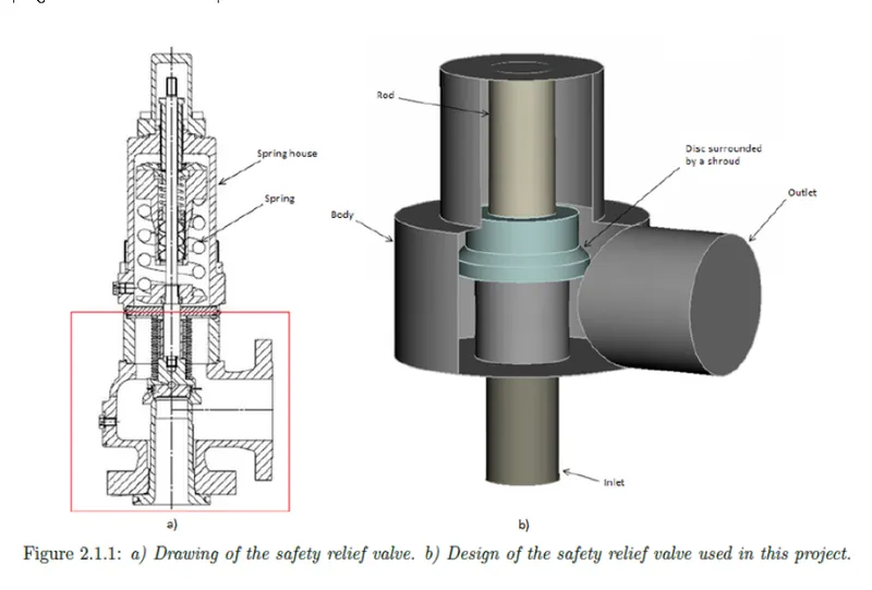
Proportional valve modelling
In steady state simulation, it is assumed that no force is acting on spindle. The lift is adjusted manually and simulation is carried out. Three lifts are used, 3mm, 4 mm and 5 mm, with and without AMR.
The transient simulation is carried out by considering hydraulic forces om disc, initial tention exerted by spring, and the gravitational force.
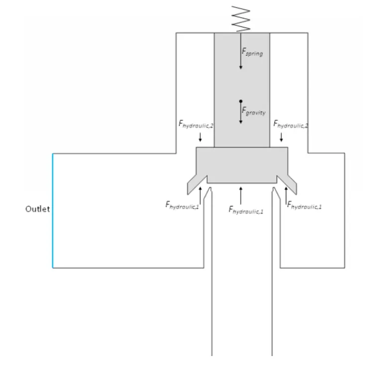
Case set up
Geometry and flagging
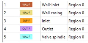
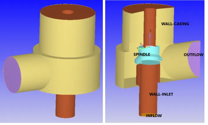
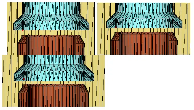
Material: Air
Mesh
The base mesh size is 4e-3 in all directions. AMR is applied to steady state simulations. AMR is not applied to transient case by considering time and computational resourses.
Boundary conditions
Inlet: Air is incoming fluid at a pressure of 30 bar and 300 K.
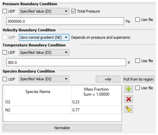
Outlet: The pressure at outlet is 101325 bar and back flow species is air at 300 K.
Wall, wall-inlet and spindle is specified as wall with law of wall boundary conditions at 300 K.
Initial conditions
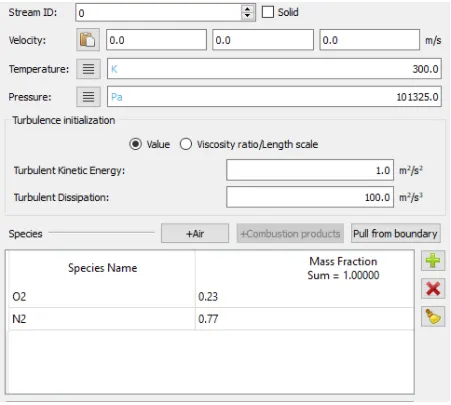
The region consist of air at 300 k and 1 atm pressure.
Simulatuon time parameters
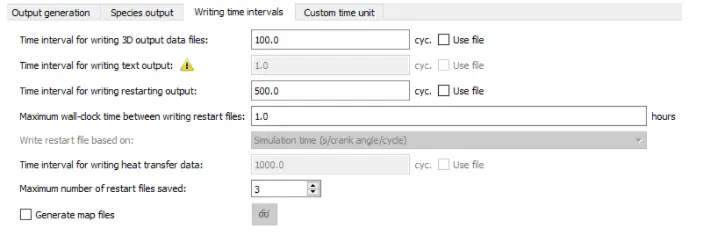
PISO algorithm is used to to solve the problem. The simulation end time is 15000 cycles.
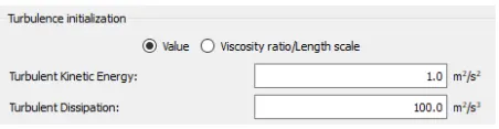
Turbulance models
RNG k-e turbulance model is selected.
Output and postprocessing
Gravity forces
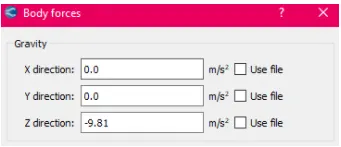
Body force is enable along z-direction as valve moves along z-direction.
Pressure forces on wall
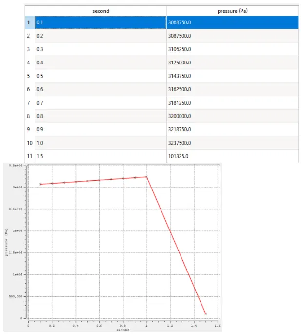
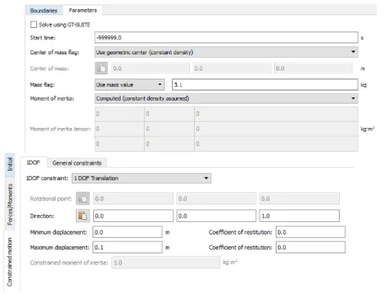
- Now under physical models, FSI is enabled. with FSI interaction of spindle (structure) and and air (fluid) is captured. A rigid FSI is applied to spindle boundary. The mass of spindle is assumed to be 3.1 kg. The initial tention in spring is assumed to be 7126 N. 1 DOF motion is enabled to restrict the motion of spindle to one direction translation. In boundary conditions, spindle wall motion is changed to FSI.
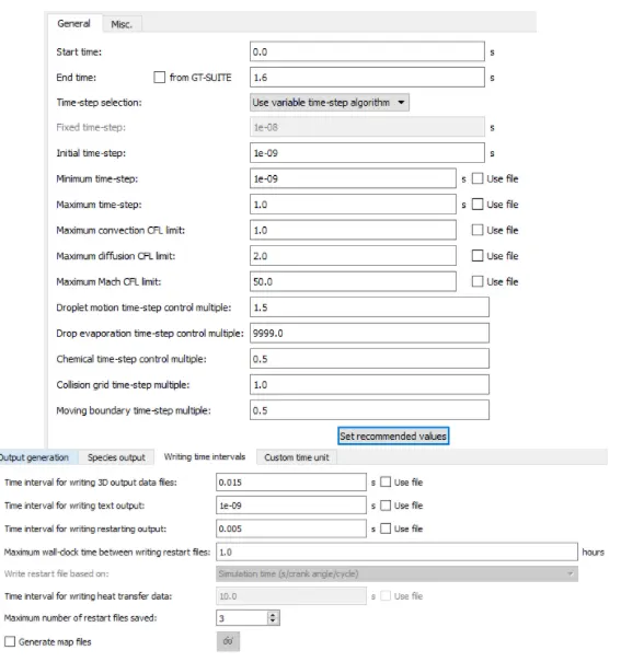
- Now simulation end time is set to 1.6 seconds, as pressure array has time upto 1.5 seconds.
Results
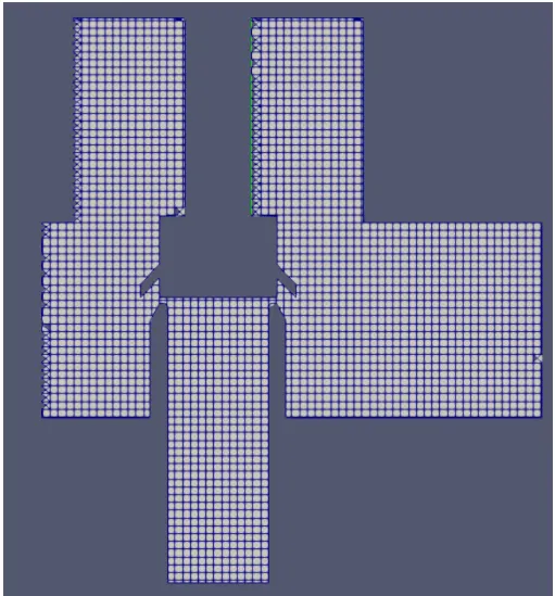
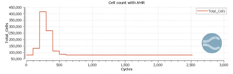
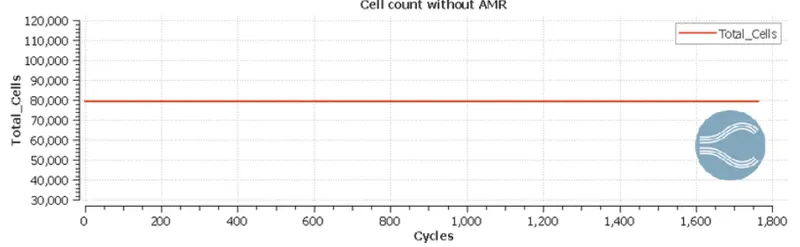
With and without AMR nesh looks like same. For both with and without AMR, no of cells in steady state is same, around 80,000.
Table: No of cycles for convergence
| Spindle lift | With AMR | Without AMR |
| 3 mm | 2568 | 1764 |
| 4 mm | 2469 | 1397 |
| 5 mm | 2520 | 140 |
Check for convergence
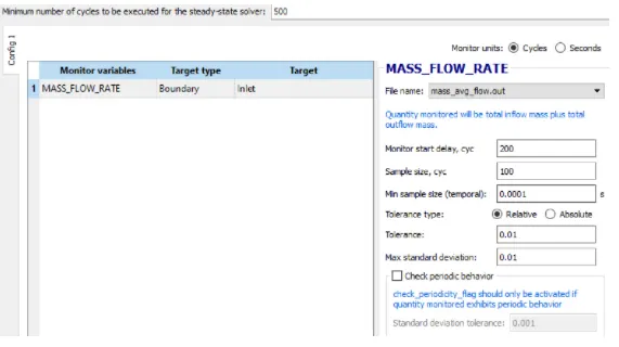
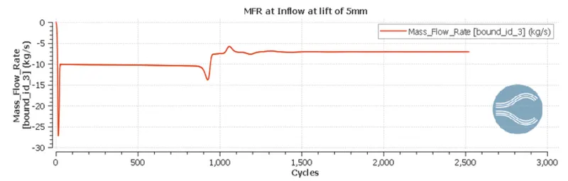
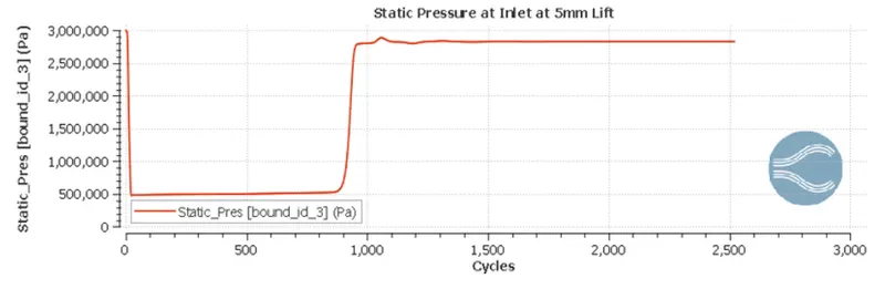
- Convergence is checked for 5 mm lift for mass flow rate at inlet and static pressure. Similarly convergence is acheived for 3 mm and 4 mm lift.
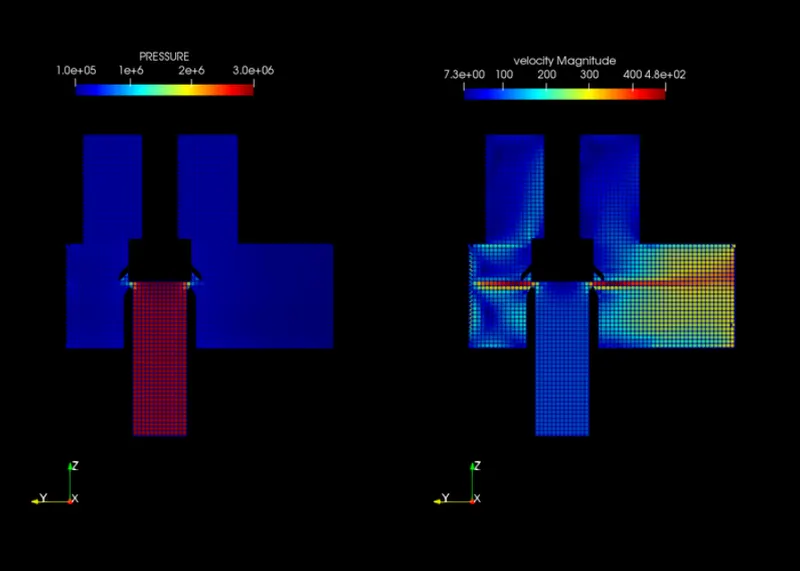
Contours of velocity and pressure for 5 mm lift
With AMR
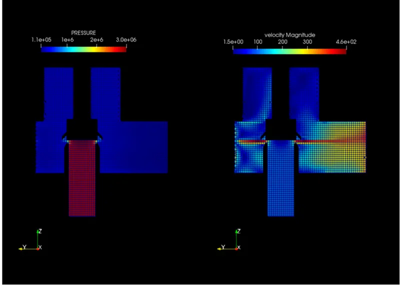
Without AMR
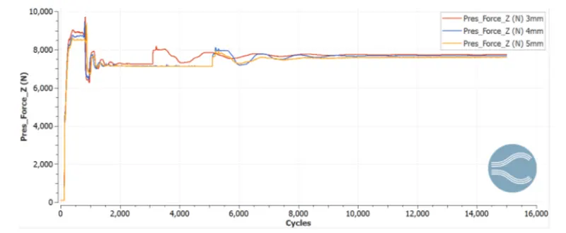
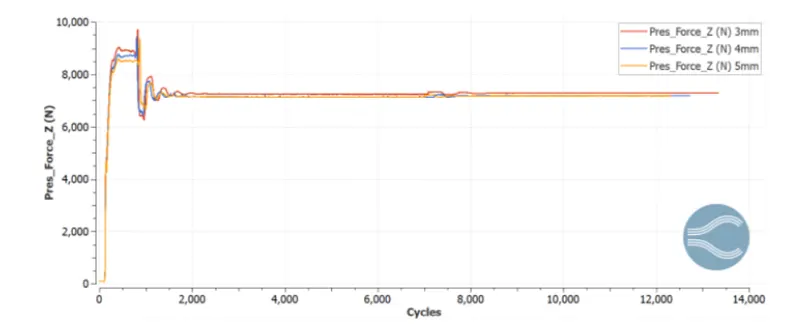
Plot of pressure force Vs lift
With AMR
Without AMR
Interferences from above plots
- From the plot of pressure force Vs lift, for both meshes, it is observed that, as the lift increases, the pressure force acting on spindle decreases.
- Mesh with AMR captures pressure gradient more accurately.
Results for FSI simulation
Animation for pressure and velocity contours
- The transient behaviour of the wall is clear from animation.
- With increase in pressure force, the spring force and weight of spindle is ovecomed and excess pressure is releived. Once the excess pressure is releived, the spring pushes back the spindle downwords. And this events repeats after the according to pressure force.
Position velocity and force plots
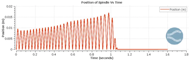
- With spindle time position is changing with repsect to original position. Once the pressure is relived, the spindle is coming to its orginal position.
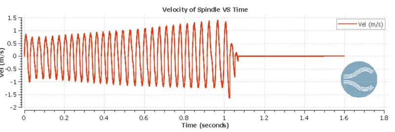
- Velocity is oscillating in nature because, spindle backs and forths in position.
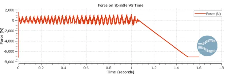
- After 1 seconds, the pressure is relived completely. So force acting will be onle weight of spring 7126 N, which is negative as it is acting in downword direction.
Conclusion
- In steady state simulation, it is observed that, as the lift increases, pressure force acting on spindle decreases.
- In FSI simulation, with increase in pressure force, the amplitude of oscillation increases.