Week 10: Project 1 - FULL HYDRO case set up (PFI)
AIM: Simulaton of PFI engine using CONVERGE.
OBJECTIVE:
1. To find out the compression ratio of this engine from input data provided.
2. Why do we need a wall heat transfer model? Why can't we predict the wall temperature from the CFD simulation?
3. To find out the combustion efficiency of this engine
4. To determine the power and torque for this engine by using the engine performance calculator.
INTRODUCTION:
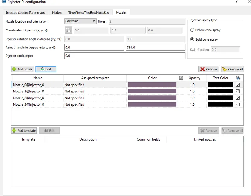
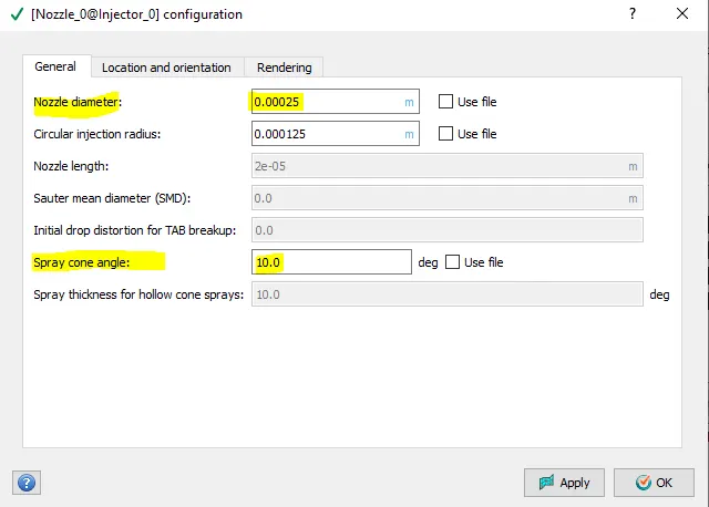
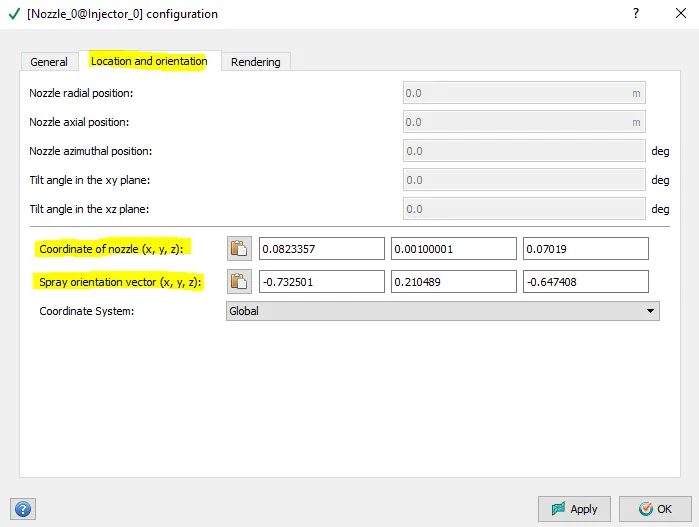
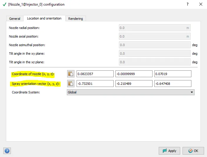
In this simulation we are interested in full hydro case set up of a premixed combustion engine(SI engine) where air and fuel are mixed before injected into the cylinder region.
- We will study the combustion ,performance and emission parameters for this case set up and also to calculate the power it produce on given rpm.
It is a resonable assumption that the fuel injected into intake port is homoenously mixed by the time the combustion is initiated.
CASE SET UP:
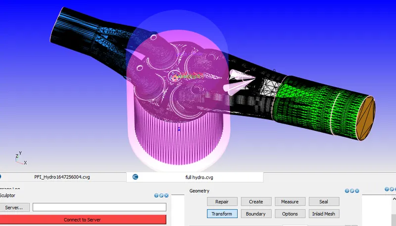
Fig.1
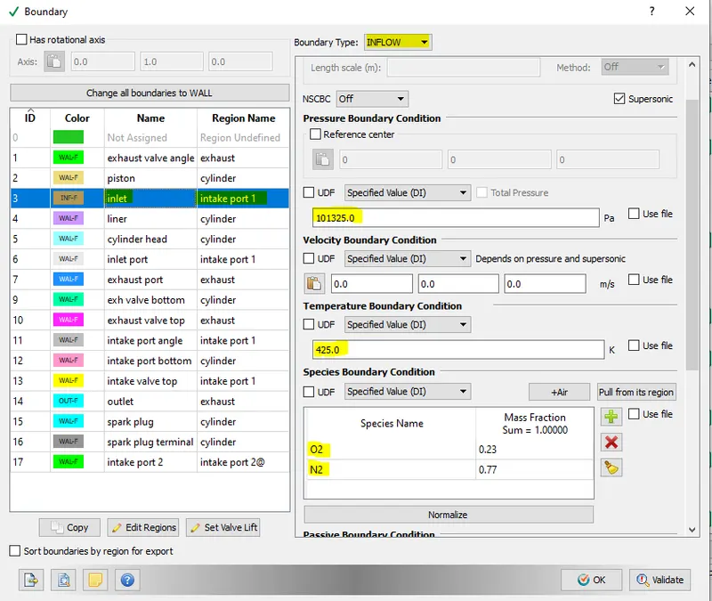
Fig.2 Boundary case set up
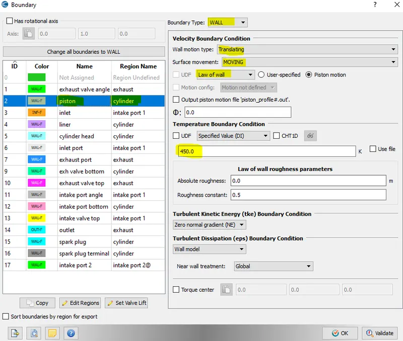
Fig.3 Boundary case set up
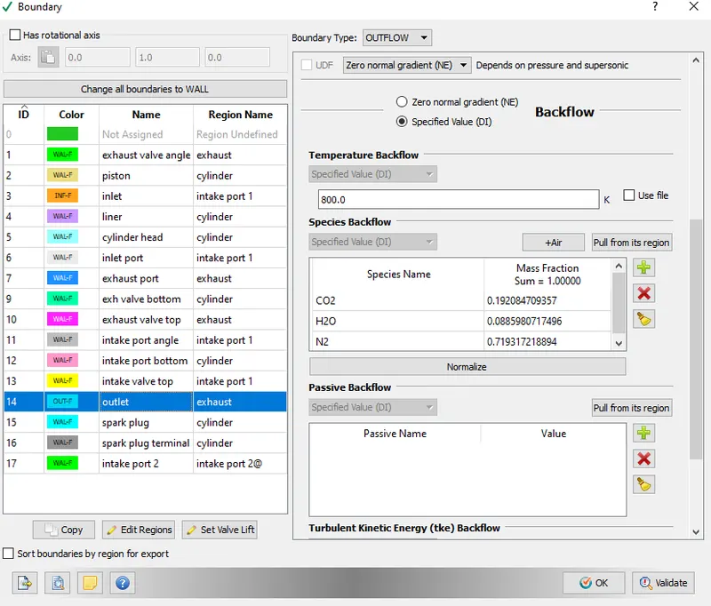
Fig.4 Boundary case set up
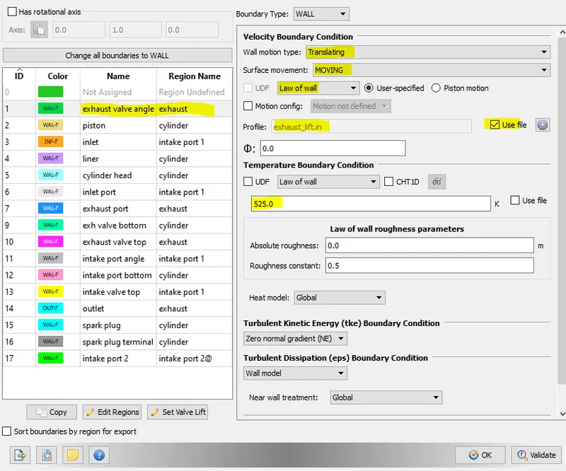
Fig.5 Boundary case set up
Region Initialization
| ID | REGION NAME | BOUNDARY ASSIGNED | INITIAL CONDITION |
| 0 | CYLINDER |
|
|
| 1 | INTAKE PORT 1 |
|
IC8H18: 0.025508 O2: 0.20157 N2: 0.77292 |
| 2 | INTAKE PORT 2@ |
|
|
| 3 | EXHAUST |
|
|
Embedding
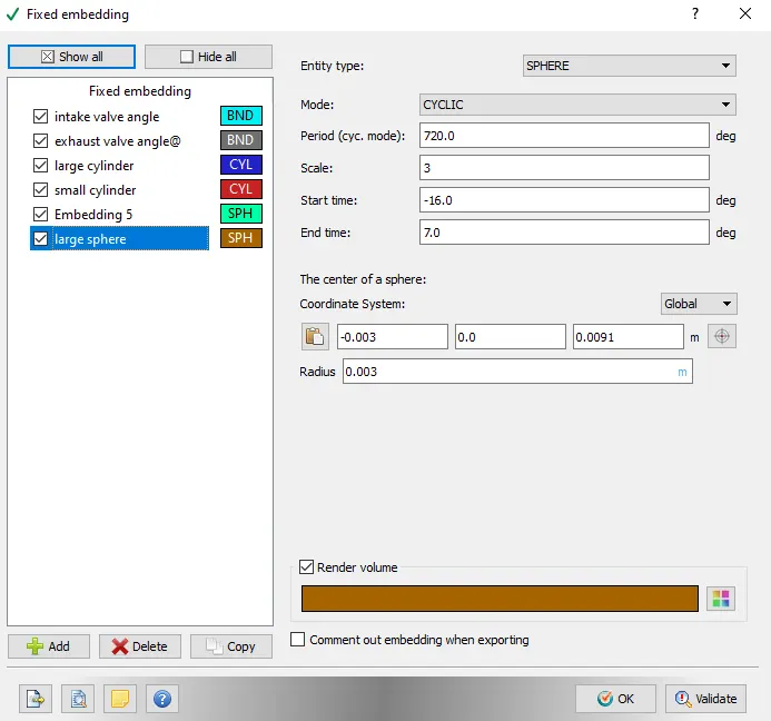
Fig.6
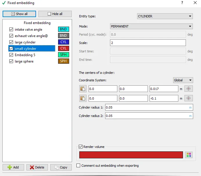
Fig.7
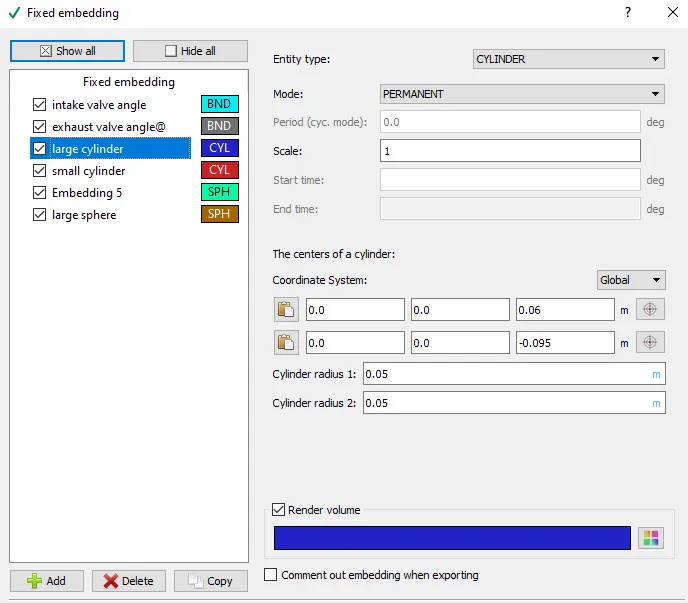
Fig.8
| Fixed Embedding | Entity Type |
Boundary ID/Mode |
Scale |
Embed layer |
Start Time | End Time |
Cylnder radius 1 |
Cylinder radius 2 |
|
Intake valve angle |
Boundary |
Intake port angle |
3 | 1 | ----- | ------ | ||
|
Exhaust Valve angle |
Boundary |
Exhaust valve angle |
3 | 1 | ----- | ------ | ||
|
Large Cylinder |
Cylinder | permanent | 1 | ---- | ----- | ------ | 0.05 | 0.05 |
|
Small cylinder |
Cylinder | permanent | 2 | ----- | ------ | ------ | 0.05 | 0.05 |
|
Spark plug |
Sphere | Cyclic | 5 | ----- | -16.0 | 7.0 | radius:0.001 | |
|
Large Sphere |
Sphere | Cyclic | 3 | ------ | -16.0 | 7.0 | radius:0.003 |
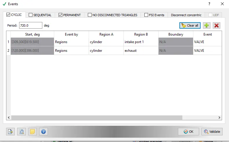
Fig.9 Events case set up
- Events are created in order to start and end some process which are of interest of user or according to the requirement.
- In this case we want that the intake valve and exhaust valve should open and close without any interference.For that we have some regions defined in the case set up.
A region is a collection of boundaries used to delineate different areas in the geometry(e.g, intake port).
- Regions are useful for variety of reasons: first one is control flow between regions(via events).
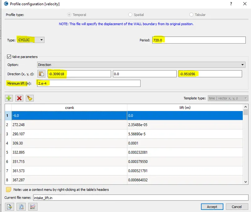
Fig.10 Intake valve lift profile
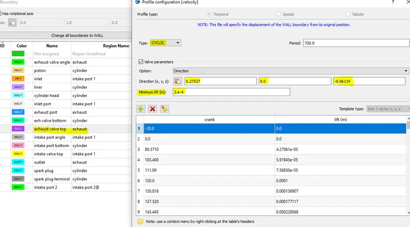
Fig.11 Exhaust valve lift profile
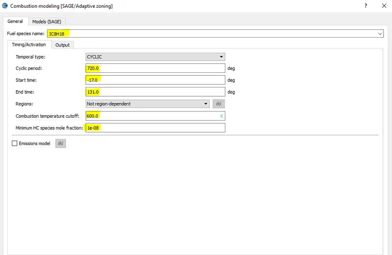
Fig.12
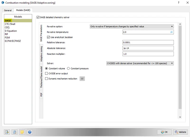
Fig.13 Combustion modelling set up(sage combustion model)
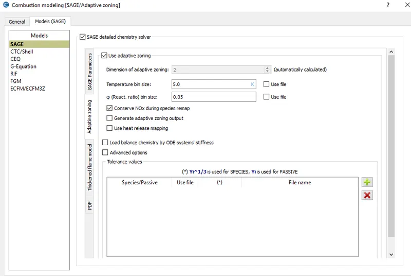
Fig.14
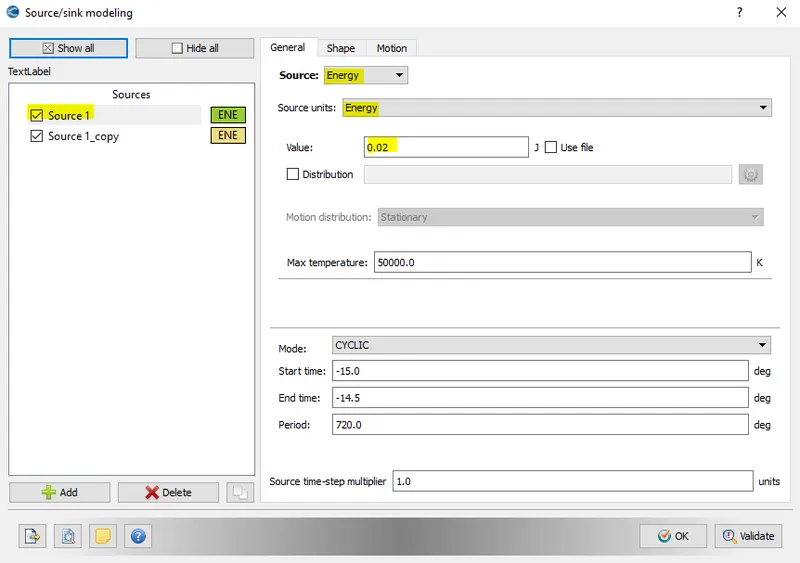
Fig.15
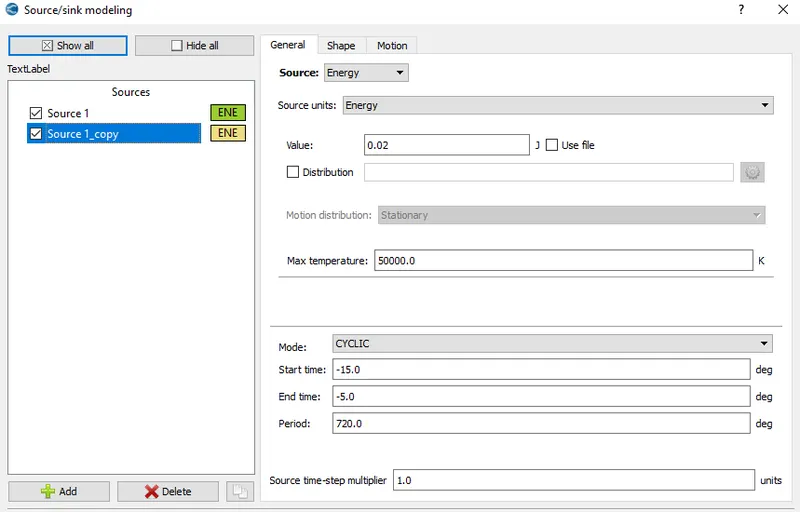
Fig.16
Spark Ignition Parameter
- Start of spark =-15 deg
- spark duration =10 deg
There will be two power source ,first one is operating for 0.5 deg and providing 20 mj of energy. Whereas second one is operating for 10 deg crank rotation and providing 20 mj of energy.
So, for 0.5 deg duration ,the energy released is 40 mj.It is provided to ignite the mixture and after ignition the energy provided for combustion is reduced to 20 mj but for longer duration of crank rotation(10 deg).
RESULTS:
PLOTS
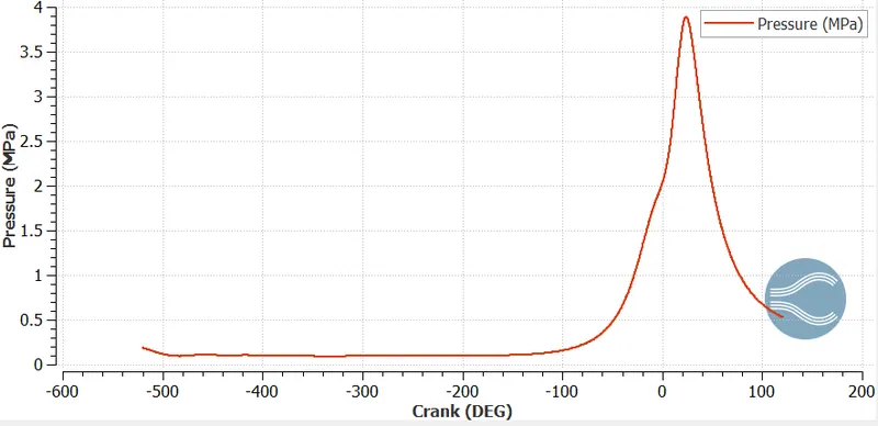
Fig. Pressure vs crank angle
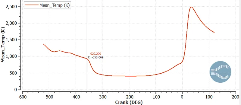
Fig. Mean_Temperature vs crank angle
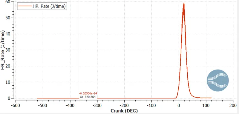
Fig. Heat Release rate vs Crank angle
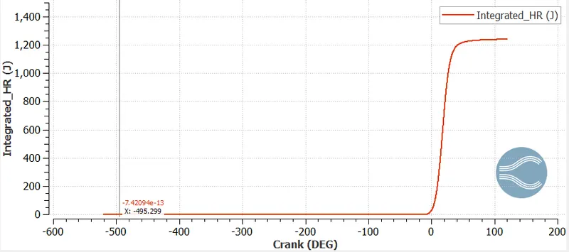
Fig. Integrated_Heat_release_rate vs Crank angle
- Combustion Efficiency =(Energy released by Burnt fuel)/(Theoretical energy content of the fuel)
= Integrated heat release (J)/(mass of fuel* lower calorific value of fuel)
= 1250/(`3*10^(-5)*(43.4*10^6)`)=0.96
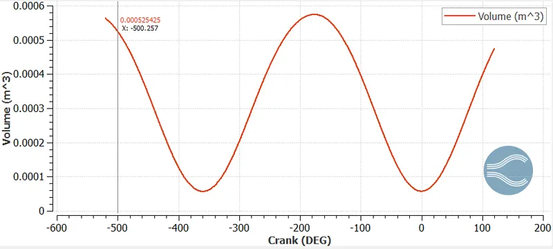
- maximum volume = `57.418*10^(-5)`
- minimum volume = `5.7042*10^(-5)`
Compression Ratio = `(V_max)/V_min=57.418/5.7042=10.06`
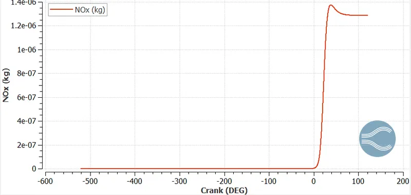
Fig. NOx emission vs Crank angle
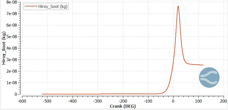
Fig. Hiroy_soot vs Crank angle
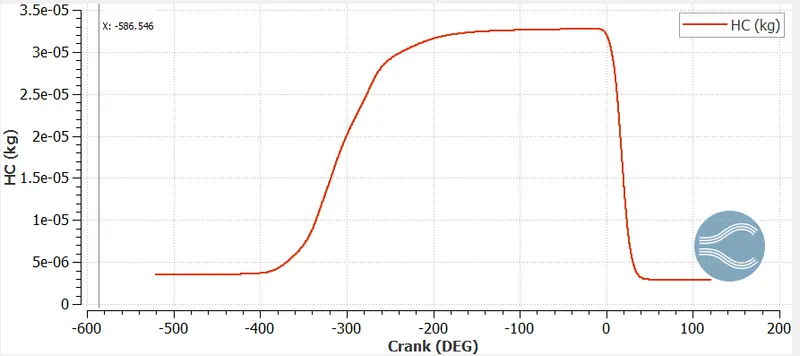
Fig. HC emission vs Crank angle
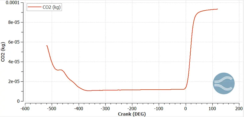
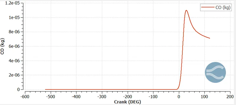
- As shown in the emission graph above for NOx,HC,CO2,CO and soot it is observed that the soot is oxidized after the combustion stroke i.e, end of power stroke. Unwanted hydrocarbons are getting oxidized keeping the emission limit to a lower value.
- We are getting high value of NOx and we an reduce it through afte rtreatment process.
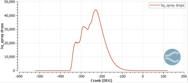
Fig. Quantity of liquid spray parcel vs crank angle at cylinder region.
- As shown in figure the liquid spray droplet parcels is around 45000 max at the cylinder region. This is the stage where the atomization process is taking place.The parcel count decreases as the spray enters the combustion chamber.This shows that the liquid parcel vapourized prior to combustion.
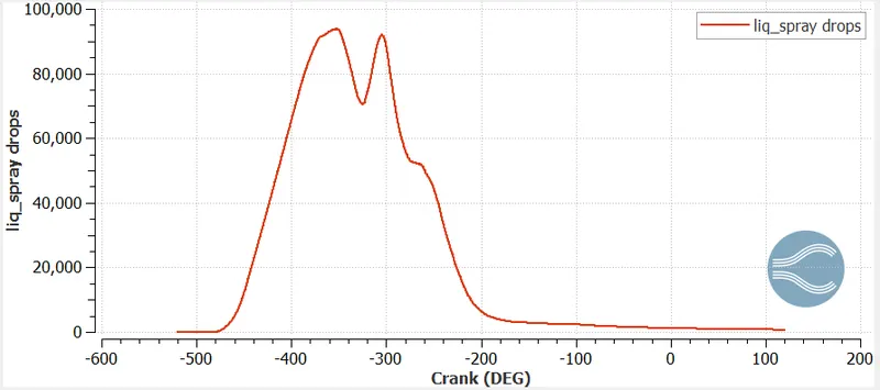
Fig. Quantity of liquid spray parcel vs crank angle at intake port region near the cylinder
- As shown in figure the liquid spray droplet parcels is around 95000 max at the intake port region.before entering to combustion chamber, there is high concentration of liquid parcel present at the intake port and as soon as the valve opens ,it enters the combustion chamber and vapourize.
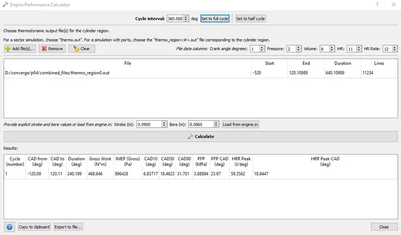
- here we have ,Time (duration in degree) = 240 deg
- Now,we have crank shaft rotation (N) = 3000 rpm = (3000* 360)/(60) (deg/sec)
now, time = Time (deg)/(Time)(deg/sec) = (240 * 60)/(3000*360) =1/75 sec
as we know, Work done (J)= 468.646 J
Power = 468.646* 75 W =35.14KW
For calculating Torque, using the formula `P=(2*pi*N*T)/60`
T=`(P*60)/(2*pi*N)`=(35.14 *60)/(2*3.14*3000)=111.9108 N*m
Need of heat transfer modeling
- Basically the thermodynamic combustion models which are used generally do not consider radiation coming out from soot particles.
- The temporally and spatial variation of soot particles inside the cylinder make it difficult for combustion models to predict the heat transfer.So, radiative heat transfer along with convective mode is together attached for heat transfer modelling.
Also for cfd simulation results ,we are getting the incylinder temperature of gases that is due to combustion.In order to model the heat transfer between cylinder gases and chamber walls ,we need thermal boundary layer.
To model heat transfer through solid region we need the properties of gas phase present inside the cylinder to provide the boundary condition for heat transfer to occur.
- Generally CA10,CA50 and CA90 represents how much energy released at 10 deg,50 deg and 90 deg of crank angle rotation.
Animation PFI
https://youtu.be/PpckhQk1Ge8
CONCLUSION:
- Full hydro simulation case set up was succesfully studied .
- For this engine , the compression ratio,power output and torque was calculated.
- The combustion efficiency was calculated and found to be above 0.9.
- Emission paramter was analysed and can be improved by after treatment process or by applying models suchs as EGR,LTC etc.