FULL HYDRO simulation of a PFI
Introduction
In a previous study, found here, a PFI engine was tested with a no hydro case setup, i.e. a study was performed to ensure the mesh and setup worked fine. In this study, the fully hydro setup will be performed and certain parametrers are analyzed.
Objectives
1. Identify compression ratio
2. Identify combustion efficiency
3. Determine the power and torque
Setup
Geometry
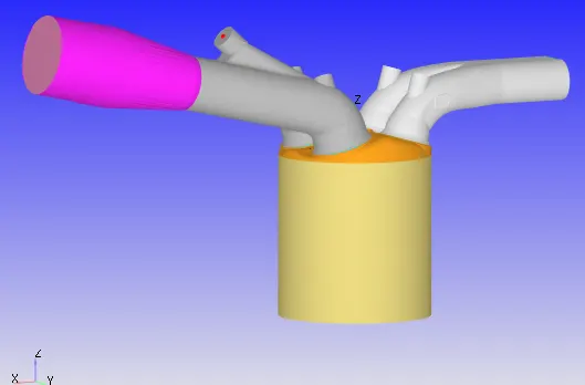
The above configuration shows the cylinder with different boundaries. These are named as:
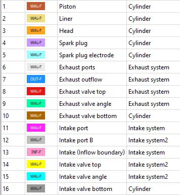
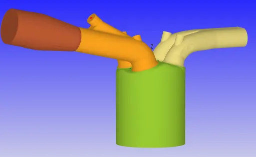
These boundaries belong to regions, shown as:
Engine geometric parameters
- Bore =0.086 m
- Stroke = 0.09 m
- Connecting rod length = 0.18 m
- RPM = 3000
Simulation time parameters
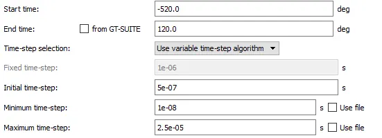
Solver parameters
PISO Navier - Stokes was used as this was the defaut scheme.
Boundary conditions
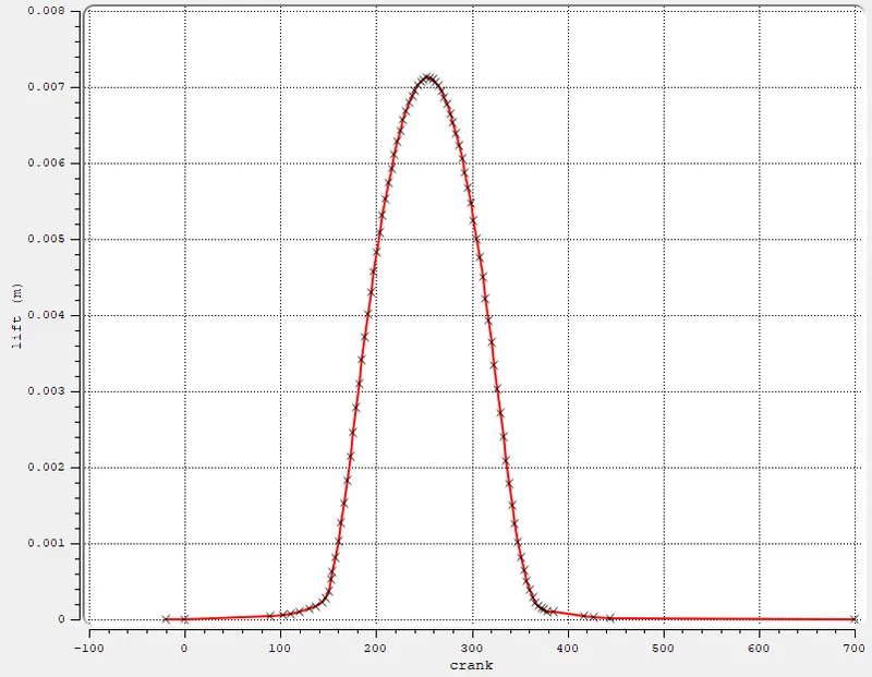
- Intake valve top, angle, bottom - law of wall boundaries, initialized with 480 K temperature, motion defined with intake valve lift profiles.
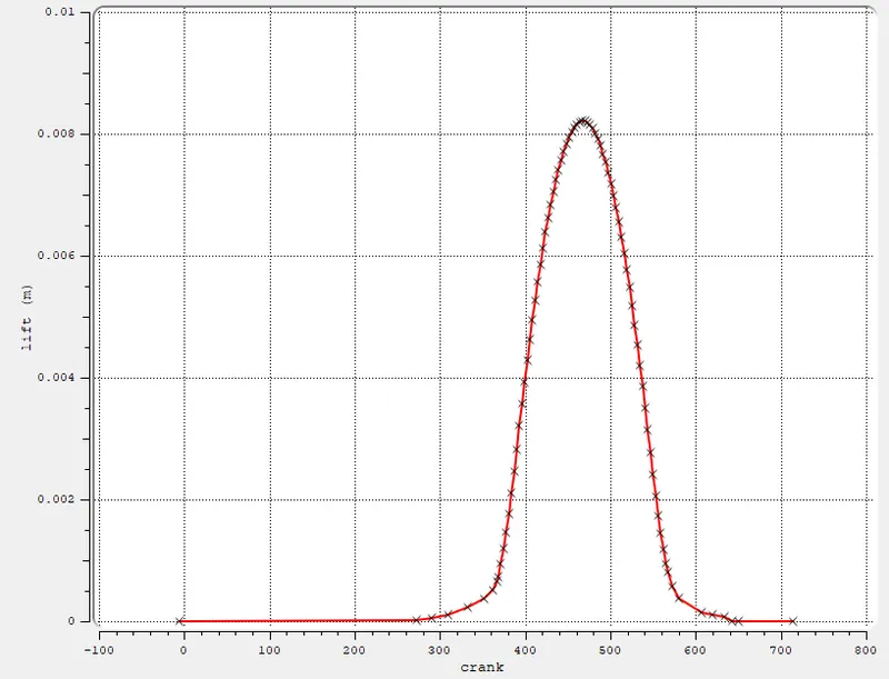
- Exhaust valve top, angle, bottom - law of wall boundaries, initialized with 525 K temperature, motion defined with exhaust valve lift profiles.
- Intake port - law of wall boundaries, initialized with 425 K temperature.
- Piston - law of wall boundaries, initialized with 450 K temperature, translating motion.
- Inlfow - inflow boundary condtion, pressure 1 atm, initialized with temperature - 363 K.
- Liner - law of wall boundaries, intialized with 450 k temperature.
- Cylinder head- law of wall boundaries, initialized with 450 K temperature.
- Exhaust port - law of wall boundaries, initialized with 500 K temperature.
- Outflow - inflow boundary condtion, pressure 1 atm, backflow initilaized with temperature - 800 K.
- Spark plug - law of wall boundaries, initialized with 550 K temperature.
- Spark plug electrode - law of wall boundaries, initialized with 600 K temperature.
- Intake port B - law of wall boundaries, initialized with 425 K temperature.
Initial conditions
- Intake system 2 (closer to combustion chamber)
- ic8h18 - 0.025508
- o2 - 0.20157
- n2 - 0.77292
- Temperature - 390k
- pressure - 1 bar
- Intake system (away from combustion chamber)
- Air
- Temperature - 370K
- Pressure - 1 bar
- Cylinder
- Pressure - 1.85731 bar
- Exhaust
- Pressure - 1.85731 bar
- Temperature - 1360K
Injection parameters
- Fuel flow rate = 7.5e-4 Kg/second
- Injection start time = -480.0
- Injection duration = 191.2
- Fuel temperature = 330K
Nozzle positions (4 nozzles are used)
Nozzle diameter = 250 micro-meter
Circular injection radius = Nozzle radius
Spray cone angle = 10
- Nozzle 0
- center 0.0823357 0.00100001 0.07019
- Align Vector -0.732501 0.210489 -0.647408
- Nozzle 1
- center 0.0823357 -0.00099999 0.07019
- Align Vector -0.732501 -0.210489 -0.647408
- Nozzle 2
- center 0.0823357 -0.0004 0.07019
- Align Vector -0.5 -0.2 -0.647408
- Nozzle 3
- center 0.0823357 0.0003 0.07019
- Align Vector -0.5 0.2 -0.647408
Spark ignition parameters
- Start of spark = -15 deg
- Spark duration = 10 deg
- Spark location = -0.003 0 0.0091
- Spark radius = 0.0005m
Exhaust and Intake lift profiles
Turbulence model
Default K-epsilon RNG model was used as this is recommended for combustion problems in Converge cfd.
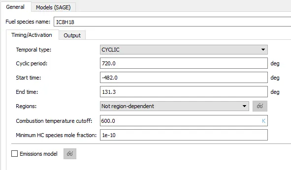
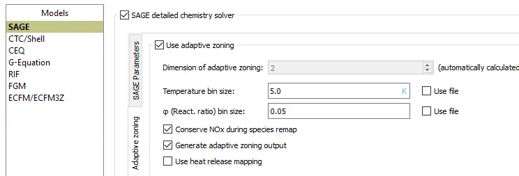
Combustion modelling parameters
Meshing details
Grid size - 0.004 m dx dy dz
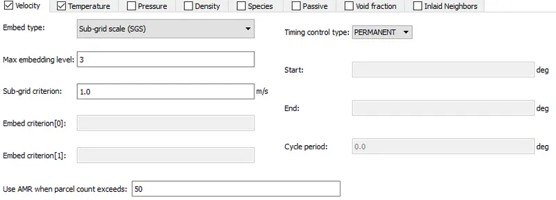
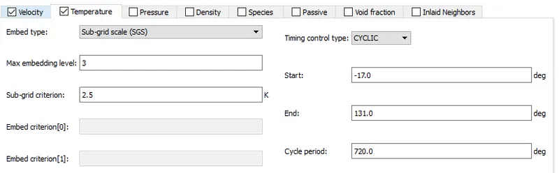
Adaptive Mesh Refinement (AMR) was used for the cylinder and the portion of intake near the cylinder. The AMR was defined to be sensitive to velocity and temperature, as shown:
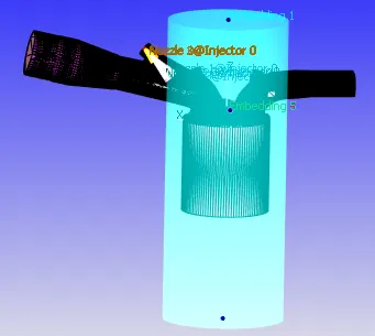
Fixed embedding (fine mesh near wall) was also added in the highlighted region:
Results
Compression ratio
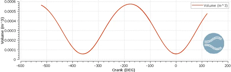
Defined as Max/Min volume in cylinder.
From the graph below,
The maximum volume can be taken as 5.74e-4 m3
The minimum volume can be taken as 5.74e-5 m3
Hence compression ratio = Max/Min = 5.74e-4/5.74e-5 = 9.97
Combustion efficiency
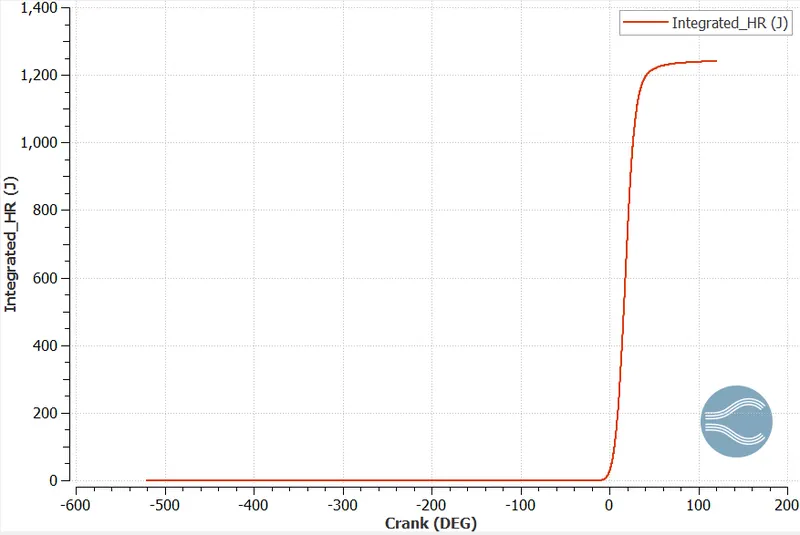
Energy content of fuel = LHV * mass of fuel per cycle = 44400e3 * 3e-5 = 1332 J.
Heat released at the end by engine durning the combustion process depicted below, is 1241 J.
Combustion efficiency = Heat released/Energy content = 1241/1332 = 93.17 %
Power and Torque
Using the engine perfrmance calculator,
Work = 468.64 Nm
Duration = 240.199 degrees
RPS = 50
Degrees per second, assuming 1 rotation as 360 degrees = 50 *360 = 18,000
Time (sec) = 240.199/18,000 = 0.01334 sec
Power = work/sec = 468.64/ 0.01334 = 35.13 KW
Torque = power/(2*3.14*RPS) = 111.88 Nm
Port Fuel Injection
Conclusion
In this study, a port fuel injection engine was analyzed using Converge CFD. Various important parameters were then calculated and the engine showed a very high combustion efficiency.