Surface preparation and Boundary Flagging for PFI engine
Introduction
Before running a simulation in Converge CFD, there exists a lot of geometry clean up and testing. In this project, the simulation is run for an IC engine to ensure that the mesh and valve movement appear to be qualitatively correct.
Aim
- Geometry cleanup
- Setting up a no-hydro case in Converge CFD for an IC engine
Procedure
On importing the STL file containing the geometry, several geometry errors are observed.
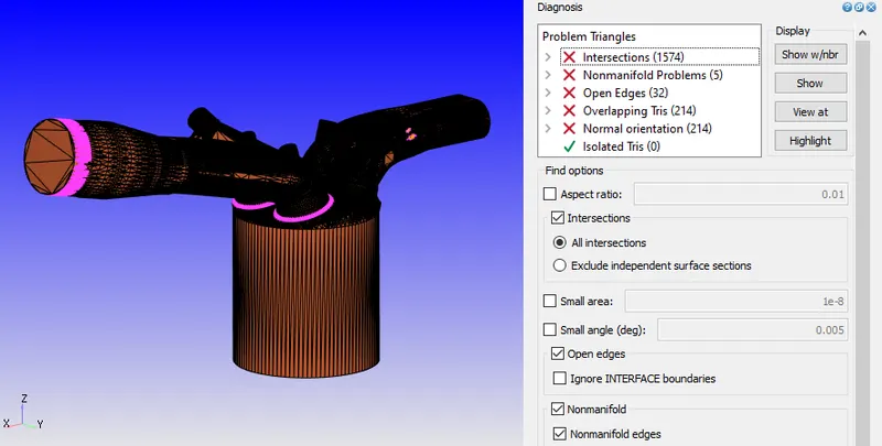
These errors are common during the designing phase using CAD programs. Converge CFD provides an efficient mode to clean up and fix almost all these errors.
Several of these errors are automaically fixed when some other error is corrected.
Few examples of correted issues:
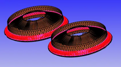
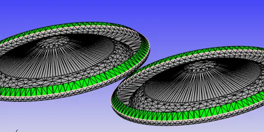
Intersection errors:
| Before | After |
 |
 |
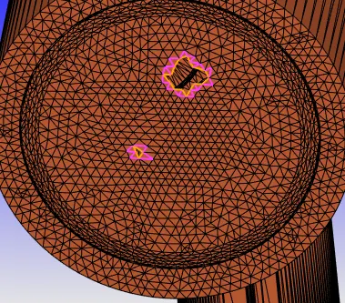
Open edges:
| Before | After |
 |
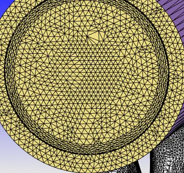 |
Other simple errors like normal orientation are fixed by transforming the normals inwards as required for CFD simulations.
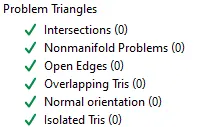
The final diagnosis can be seen with no errors:
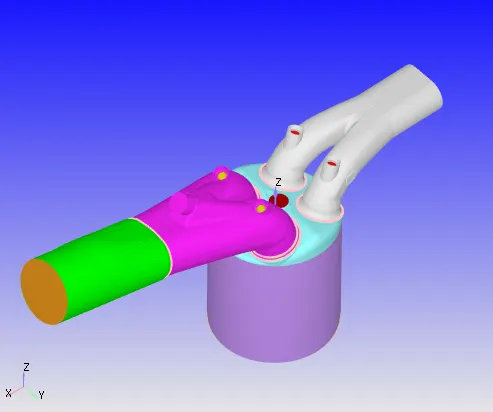
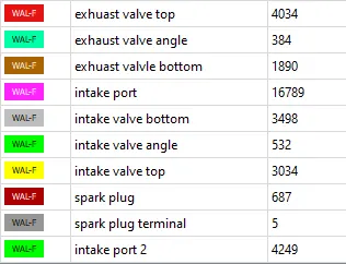
Next, each part of the ICE geometry is flagged as a seperate boundary, as shown:
 |
|
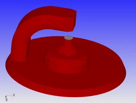
Spark plug and terminal:
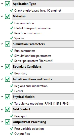
Now, a no - hydro simulation is run. This is a quick simulation done to test whether the setup parameters and geometry is valid - such as the motion of the valves, and the mesh motion.
No hydro setup:
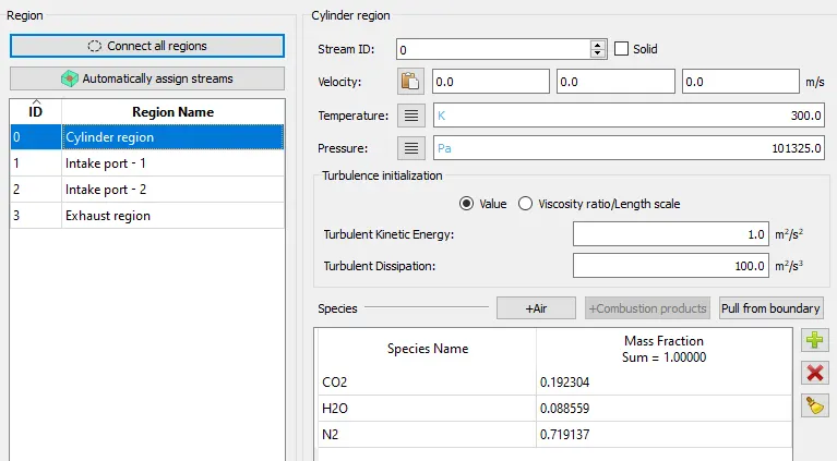
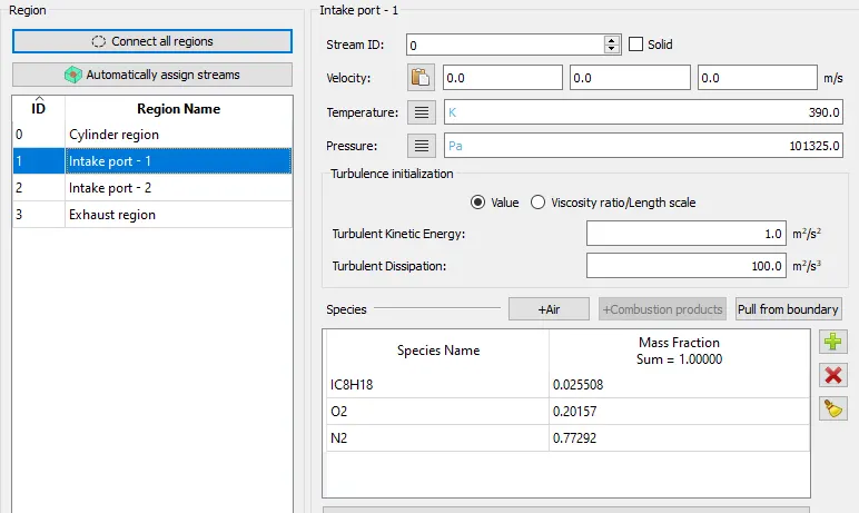
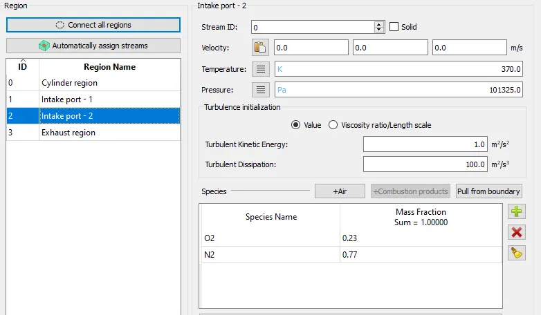
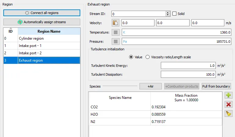
The regions are intialized with the following parameters:
 |
 |
 |
 |
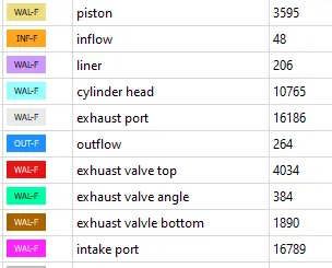
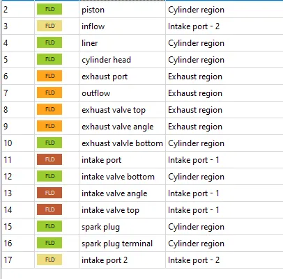
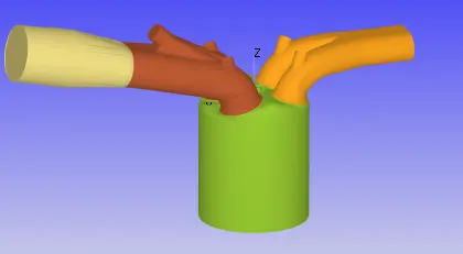
Each of the flagged boundaries are assigned to a region, given by:
Final geometry (Grouped by regions):
 |
Boundary conditions:
- Intake valve top, angle, bottom - law of wall boundaries, initialized with 300 K temperature, motion defined with intake valve lift profiles.
- Exhaust valve top, angle, bottom - law of wall boundaries, initialized with 525 K temperature, motion defined with exhaust valve lift profiles.
- Intake port - law of wall boundaries, initialized with 425 K temperature.
- Piston - law of wall boundaries, initialized with 450 K temperature, translating motion.
- Inlfow - inflow boundary condtion, pressure 1 atm, initialized with temperature - 363 K.
- Liner - law of wall boundaries, intialized with 450 k temperature.
- Cylinder head- law of wall boundaries, initialized with 300 K temperature.
- Exhaust port - law of wall boundaries, initialized with 500 K temperature.
- Outflow - inflow boundary condtion, pressure 1 atm, backflow initilaized with temperature - 800 K.
- Spark plug - law of wall boundaries, initialized with 550 K temperature.
- Spark plug terminal - law of wall boundaries, initialized with 600 K temperature.
- Intake port 2 - law of wall boundaries, initialized with 425 K temperature.
Cyclic events:

Permanent events:

Grid size of 4 mm uniform was chosen.
K epsilong RNG (default) turbulence model was adopted for no hydro case setup testing.
Animations showing valve and mesh motion: