Conjugate Heat Transfer Analysis on a graphics card
Conjugate Heat Transfer Analysis on a Graphics card
Introduction
Conjugate heat transfer analysis involves analyzing and studying the interactions of thermal energy between solid and fluid materials. Using Ansys Fluent, this phenomenon can easily be simulated and studied.
CHT analysis has many applications, such as in exhaust manifolds, radiators, heat exchangers, and many more.
In this experiment, a study is done analyzing the flow over a graphics card. The processor is assumed to be the central heat source, as it generally is.
A standard graphics card model is used to perform all the studies.
Aim
- To study the effect of varying inlet velocities of air for a graphics card
- To plot temperature OF air flow over a graphics card
- To identify maximum heat transfer coefficient and temperature attained by the processor
Modeling approach
The following model has been imported into space claim.

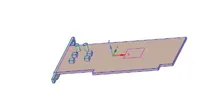


Base Fins Processor
An enclosure has been created to simulate the air flow in and out.
The share prep feature has been implemented in order to obtain a conformal mesh. Share topology is also enabled for the same reason.
Procedure
Named selections have been created as inlet, outlet, symmetry and wall boundary condition has been applied for the enclosure.
Mesh details
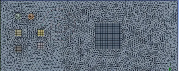
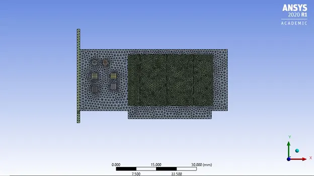
Details for body and face sizing
Body and Face sizing (for capacitors) has been performed specifically for the graphics card components to get a fine mesh in these regions
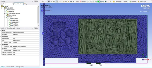
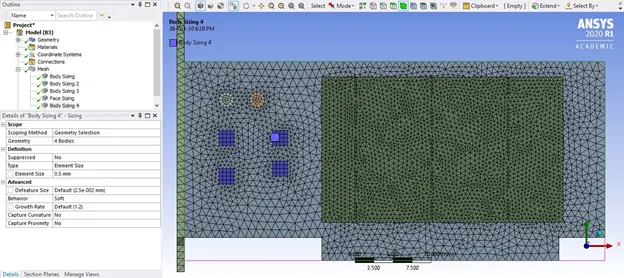
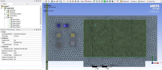
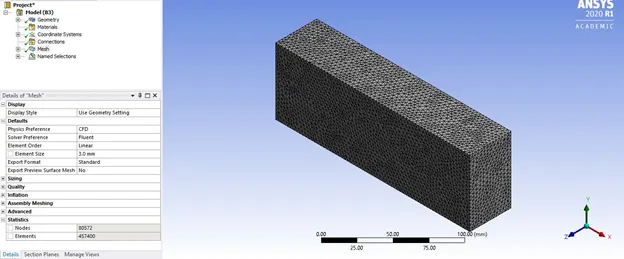
Total number of elements = 457,400
Fluent Details
In this experiment, three different inlet velocities will be simulated
1,3,5 m/s
Turbulence model: K omega SST (Since we want to capture wall heat transfer coefficient)
Steady state solver
Base material: Aluminum
Processor material: Gold
Fins material: Steel
Assuming 10W of heat generation, and volume of processor as 64 mm^3
Heat generated/m^3 = 156250000 Watt/m^3 (By the processor)
The processor is considered as the only source of heat, thus the source term function has been enabled in the cell zones section, and the value of heat generated has been added.
Case 1
Inlet velocity – 1 m/s
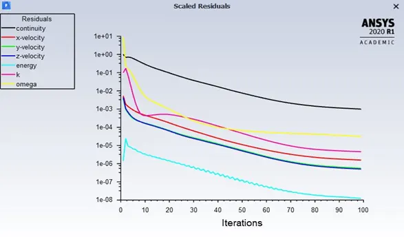
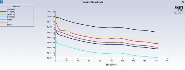
From the scaled residuals, it can be inferred that convergence has occurred
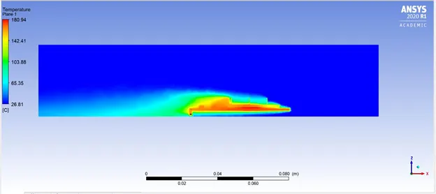
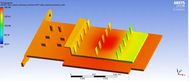
A lower temperature can be observed at the entry region (right). This is mainly because of cooling from the inlet air.
Poor cooling and heat transfer takes place as seen, the base is at a very high temperature. Even the fins have a high temperature not just in the center but overall, and a low temperature region is only visible towards the right (inlet)
Overall temperature obtained by the processor is 181⁰C.
It is expected that as the velocity increases, there will be a decrease in max. temperature generated by the processor.
A hotspot is observed towards the center, due to heat generated by the processor.
Case 2
Inlet velocity = 3 m/s
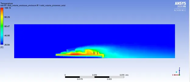
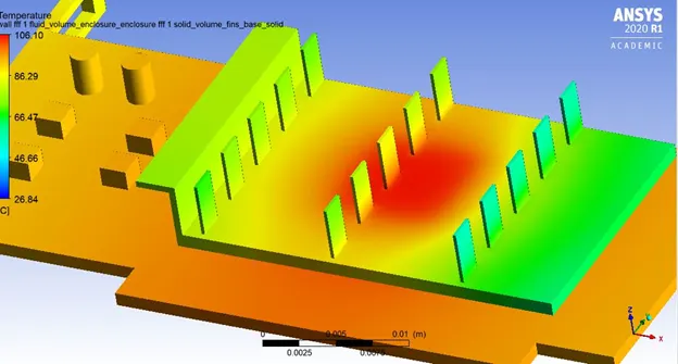
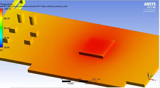
As expected, the max. temperature has reduced to 106⁰C. This is due to a higher inflow of velocity at 3 m/s. A local hotspot is observed at the processor, fins, and base.
Also, temperature is slightly lower to towards the right of processor, because of cooling during air inflow.
The fins towards the right also have better cooling, when compared to case 1.
Case 3
Inlet velocity = 5 m/s
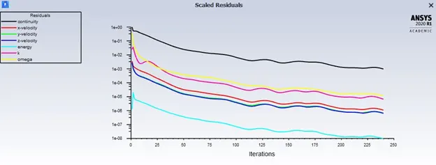
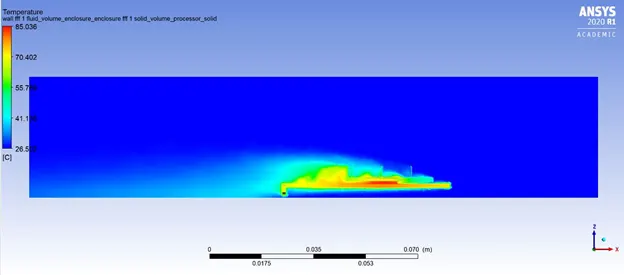
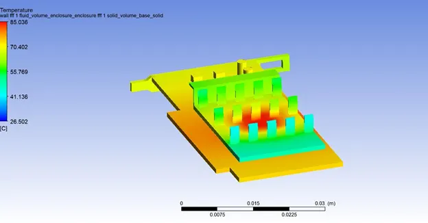
This is the most optimum case from all three cases. Proper cooling occurs of the fins, and even the base has a lower temperature due to cooling.
The maximum temperature recorded for the processor in this is only 85⁰C.
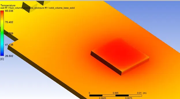
Also, temperature is slightly lower to towards the right of processor, because of cooling during air inflow.
The fins towards the right also have better cooling, when compared to case 1 and 2.
Observations
|
Inlet velocity (m/s) |
Max. Temperature (⁰C) |
Wall heat transfer coefficient (w/m2-k) |
|
1 |
181 |
48,483.446 |
|
3 |
108 |
74,892.444 |
|
5 |
85 |
249,660.6 |
Conclusion and Inferences
- As the inlet velocity increases, the maximum temperature of the processor decreases
- At a velocity of 5 m/s, the maximum temperature has gone down to 85⁰ This is ideal as most graphics cards have temperatures in the range of 50⁰C to 90⁰C.
- The temperature of the graphics cards region towards the inlet is lower.
- The central area which contains the processor will be the region with the highest temperature. Hence the base, and the fins will also have the highest temperatures in this region (Hotspots). Thus it would be advisable to not place any material in these regions.
- As velocity increases, there is an increase in Reynold's number. Thus the wall heat transfer coefficient increases with increase in velocity,