Ahmed Body
Flow simulation over an Ahmed body
Aim:
- To simulate flow over an Ahmed body by creating a wind tunnel enclosure.
- To study the flow of air over an Ahmed body and identify the values of drag for different levels of mesh refinement.
- To understand the phenomenon of the wake region and its associated effects.
- To understand the significance of point of separation.
Theory:
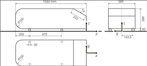
Ahmed body: In engineering applications, studying the aerodynamics of a vehicle is quite challenging due to the presence of a variety of different vehicular designs. Hence a generic bluff body, known as the Ahmed body was created that represents a basic model of most vehicles.
Wake region: Wake region is one of the most important regions to analyze during flow over any body as various force reports including but not limited to drag can be calculated. It is the region where turbulent forces are high inside the boundary layer, and exists beyond the point of separation.
Procedure:
2 cases are run. For the first case, a baseline coarse mesh was used just to perform a routine run. Next, the mesh is refined and the results of the coefficient of drag are compared to experimental data.
Base line simulation:
Post processing
For the baseline simulation, the procedure is as follows.
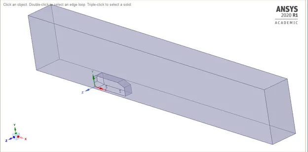
First, an enclosure is created using spaceclaim to simulate a wind tunnel. The body is split in half as the symmetry condition can be applied at the split to save computational time.
Mesh
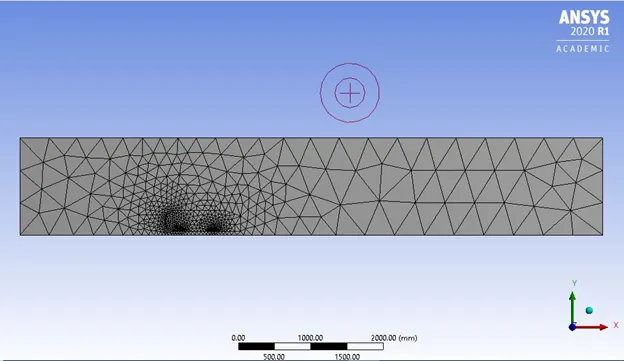
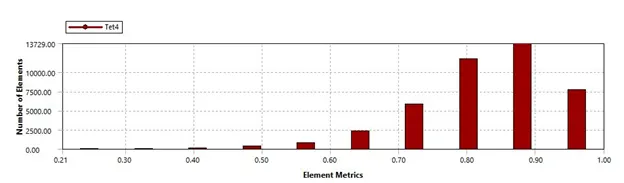
A standard mesh has been used to perform the base line simulation
Processing
Simulation details:
Inlet velocity – 25 m/s
Expected drag coefficient – 0.33
Since Mach number is less than 0.3, a pressure based solver is used.
Viscous method – K epsilon, Realizable as the flow is turbulent. (This model is just used for the baseline simulation).
Solution method - SIMPLE
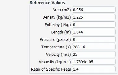
Reference values:
Results
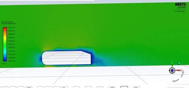
Velocity contour
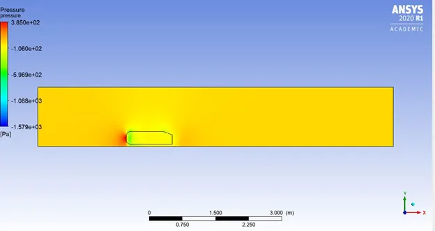
Pressure contour
Coefficient of drag
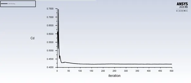
Coefficient of drag = 0.4194
Vector plot
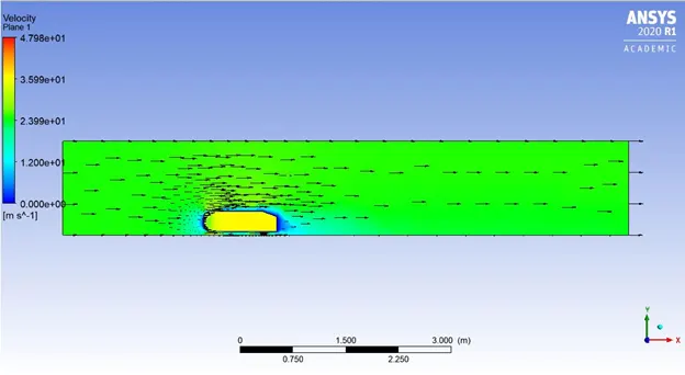
The observed results for the baseline simulation appear to just paint a pretty picture, and give a general idea of the expected results. Next, the mesh sizes were changed, and finally the most refined mesh which showed little variation was chosen.
Refined case
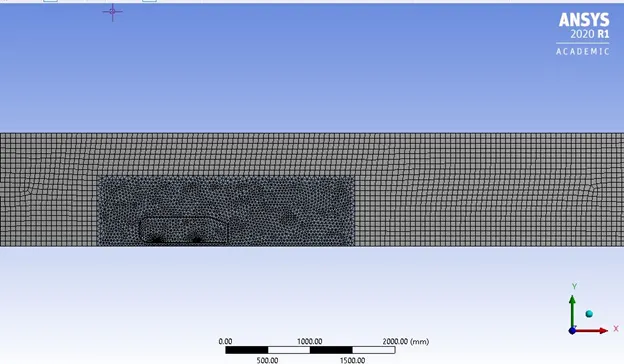
Local refinement is done by creating another enclosure around the Ahmed Body. The dimensions of the enclosure are calculated with respect to the velocity contours obtained from the base line simulation. Creating a refined local enclosure ensures the wake is captured more accurately, and increases the computatinal load only in this region thus saving overall resources.
Geometry
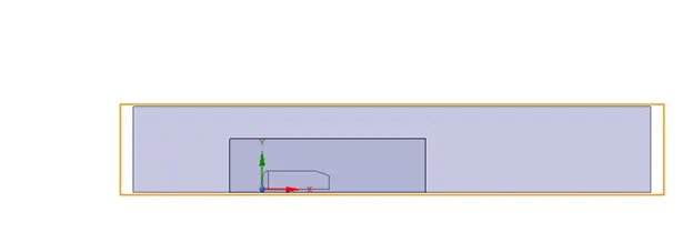
Mesh
Details
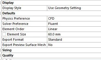
For the interior enclosure:
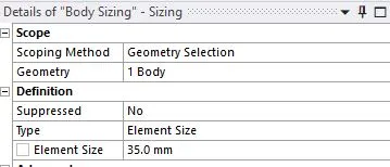
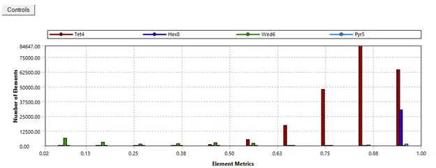
For this case, the k-omega SST turbulence model was used. This model is better suitated for near wall flows where effects such as drag are to be captured. The wall y+ of 1 was set to be in the viscous sub-layer, in order to ensure accurate drag prediction. Second order schemes were used with a convegence criteria of 1e-5 to reduce numerical error.
Results
Velocity contour
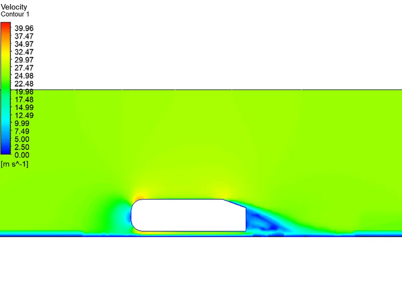
As expected, velocity stagnates at the face of the ahmed body, and then undergoes acceleraton around the edges. The wake region is more clearly observed behind the body.
Pressure
Coefficient of drag
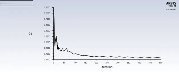
Cd= 0.36
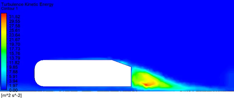
Turbulent kinetic energy
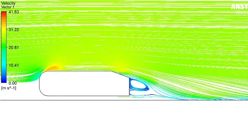
Velocity vectors mapped with streamlines
Results and Observations:
- As fluid flows over a blunt object, (Ahmed body in this case), a wake region is created behind the body, as seen in the depicted velocity contours obtained by simulation.
- The value of Drag for a velocity of 25 m/s, (turbulent Re), is 0.36 for a refined mesh after local refining, which still provides a 30% error from the expected experimental data.
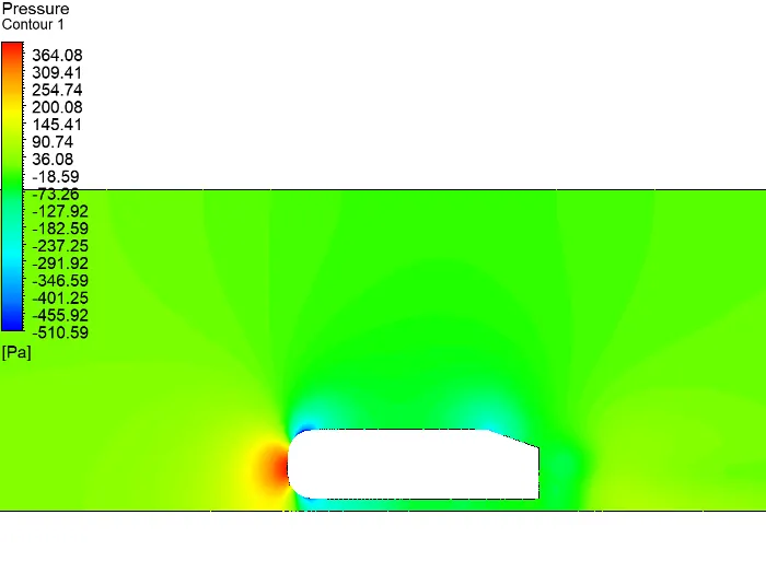
- A negative value of pressure is visible from the pressure contour.
- The vectors and streamlines clearly show high flow disturbances and recirculation in the wake of the ahmed body.
Inferences:
- When fluid flows over an object, a boundary layer is formed due to viscous forces (shear) between the fluid and the surface of the body.
- Due to the viscous forces, the fluid flow is decelerated and thus a pressure gradient is formed contributing to the separation point formation.
- This pressure gradient is undesirable as it begins to oppose the flow of the upstream fluid resulting in increase in drag acting on the body.
- Inside the boundary layer where the pressure gradient is high, turbulent flow occurs, which is seen as the wake region.