Week 10: Modeling and Simulation of flow around an Ahmed Body
OBJECTIVE:
We are to simulate flow over Ahmed's body and compare it with experimental results
GEOMETRY:
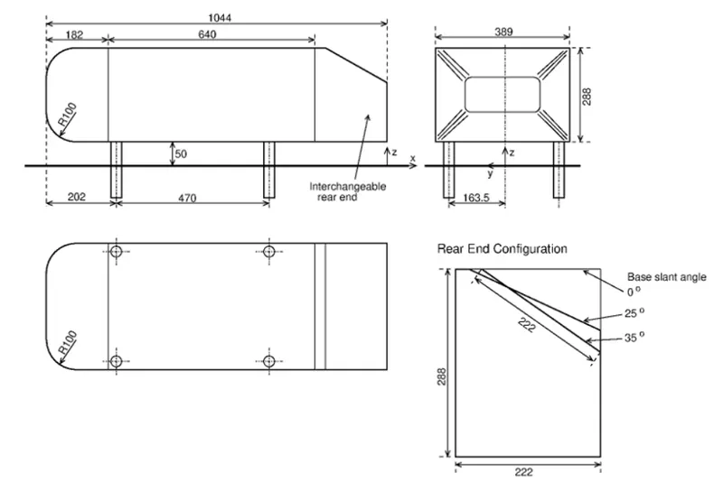
We are using the standard Ahmed Body geometry given by Ahmed et al. [1]:
 +
+
Creating the geometry in the cad package:
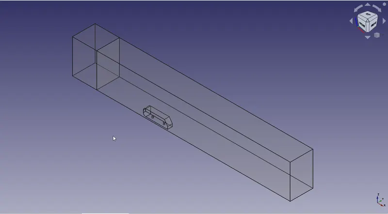
The wind-tunnel cross-section area is the same as used to obtain experimental data[2], i.e., 1.87 x 1.4 `m^2`.
The boundary layer in the experiment was observed to be 30 mm thick, 400 mm before the Ahmed body front.
To obtain the same, we have a free slip region at the beginning of the wind tunnel for a uniform velocity profile equal to our characteristic length = 1044 mm.
Following this, we have a length necessary to obtain a 30mm thick boundary layer; the following formula can calculate this:
`delta = 0.382*x/(Re_x)^(1/5)`
Flow Parameters from Experiments:
-
Kinematic viscosity of air: `15xx10^(-6)` m2/s
-
Bulk velocity: 40 m/s
therefore, `Re_x = 2784000`
Solving for x, we get 1.52m.
Hence the total length before Ahmed's body is 1.044 + 1.52 + 0.4 = 2.964 m
Given the computational resources at hand and considering standard norms, the rear end of the wind tunnel is placed five times the characteristic length distance from the rear of Ahmed's body, i.e. 5m.
The slant angle is `35^o`.
BOUNDARY FLAGGING:
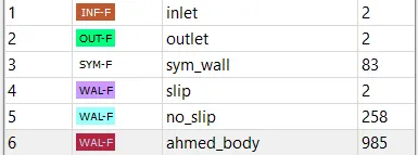
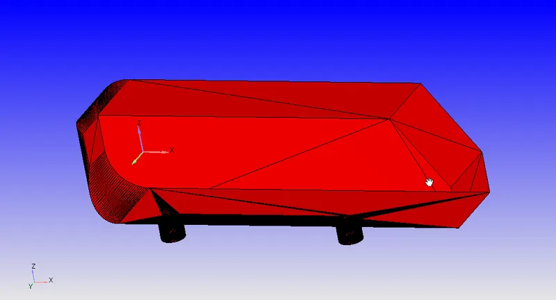
Ahmed Body:
Inlet, Slip, No-Slip and Outlet:
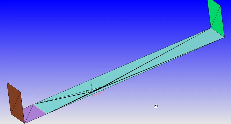
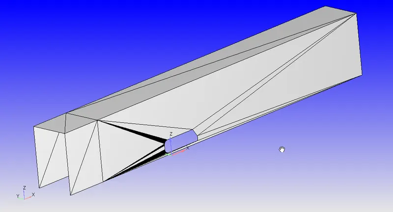
Symmetry Walls:
SIMULATION PARAMETERS:
Initial Conditions:
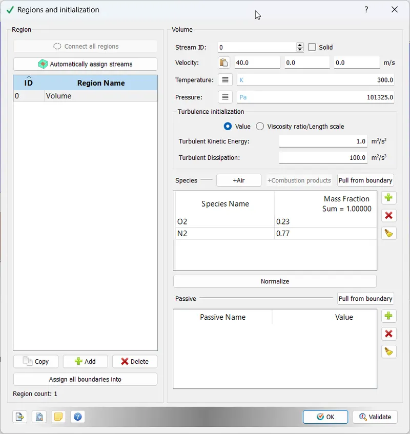
Boundary Conditions:
All boundary conditions are meant to replicate the experimental results[2].
Inlet: Velocity along the x-axis = 40 m/s at 1 atm Pressure
Outlet: Pressure outlet at 1 atm
Ahmed Body: Law of wall with default parameters
Side and Top Walls: Symmetry Boundary Condition
Bottom Wall: Slip for first 1044 mm, No-slip for rest of the wall
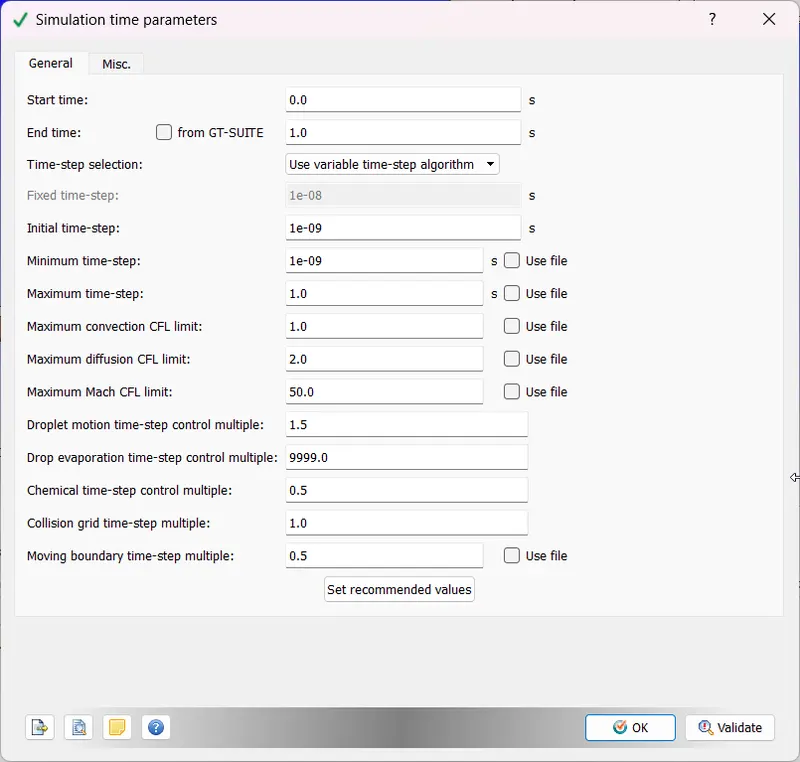
Time Parameters:
Total Wind Tunnel Length = 9m
Flow throw time =9/40 = 0.225 seconds
Simulation time = 5 * Flow Throw Time `~=` 1 second
Solver Parameters:
We are using a transient, density-based, compressible solver.
The Turbulence model being used is K-`epsilon-v^2` or `v^2-f` model, which was noted by Liu et al.[3] to be most efficient when simulating flow on Ahmed's body.
Mesh Parameters:
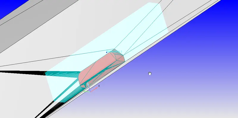
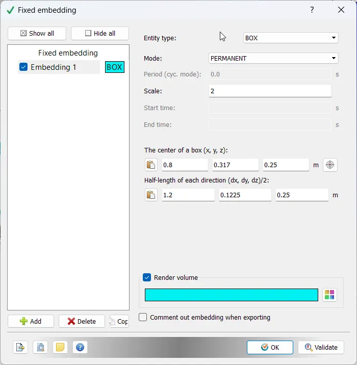
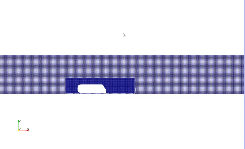
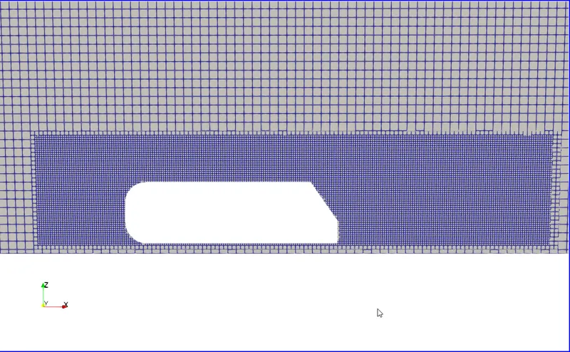
We will be using a base mesh and a refined box-type volumetric mesh near the Ahmed's Body:
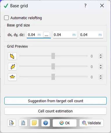
Refined Volumetric Mesh:
Output Parameters:
We have enabled the 'Boundaries Only' method in the
wall output option for output parameters to calculate Drag and Lift more efficiently.
RESULTS:
Mesh:
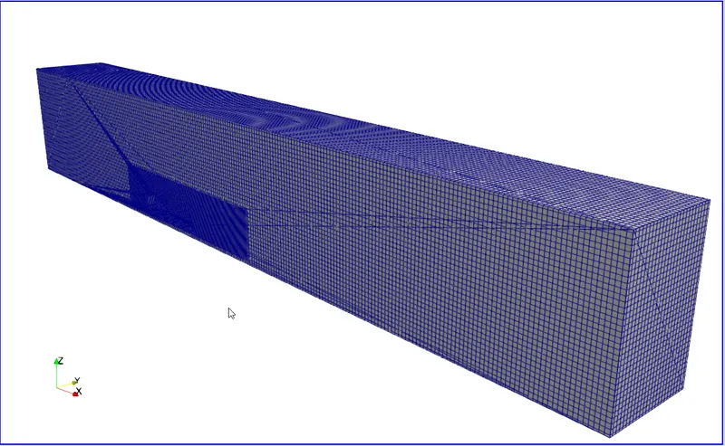
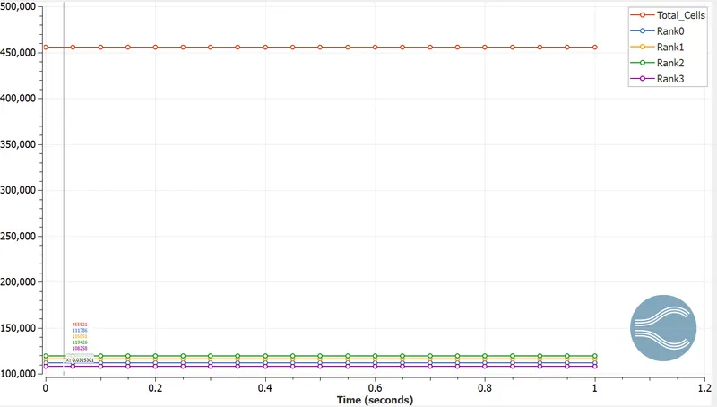
Cell Count:
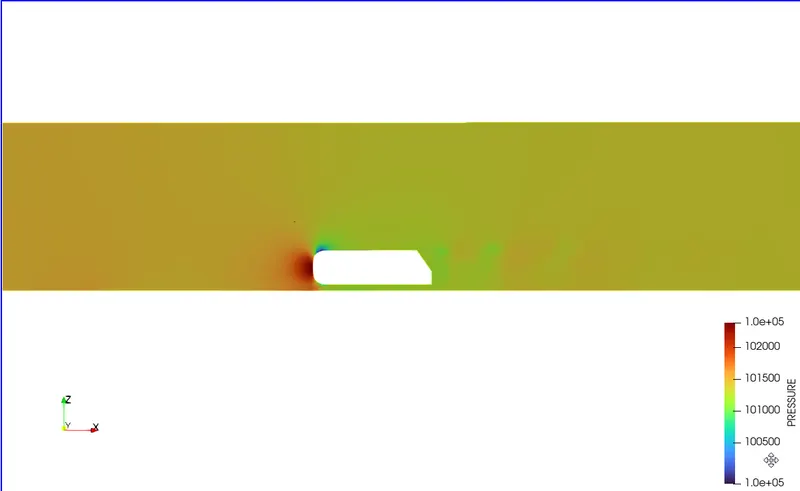
PRESSURE CONTOUR:
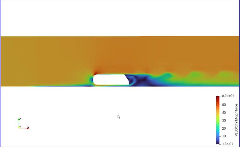
Velocity Contour:
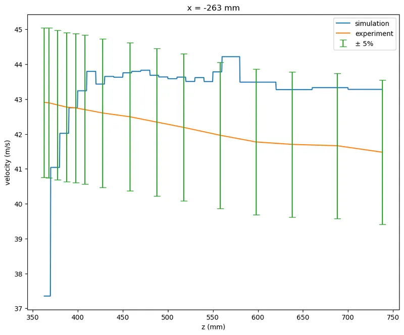
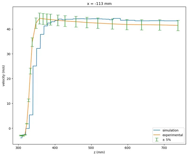
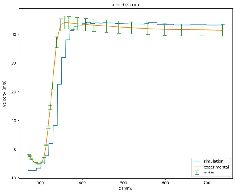
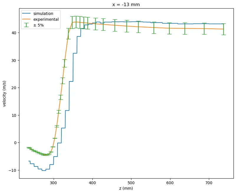
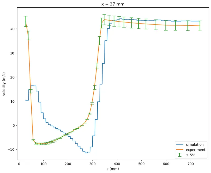
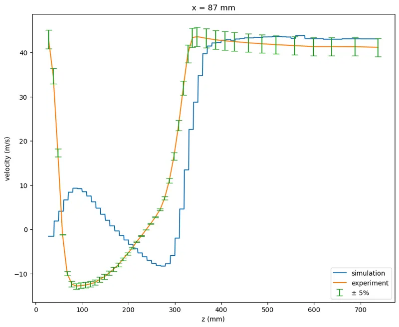
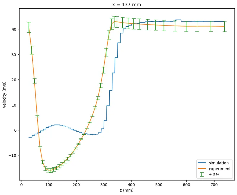
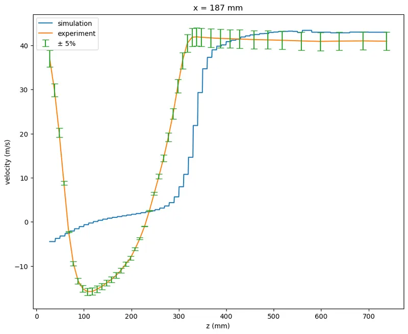
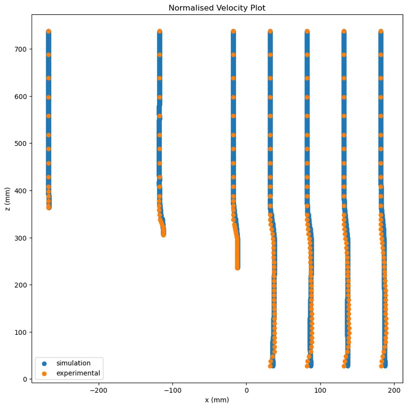
COMPARISON WITH EXPERIMENTAL DATA:
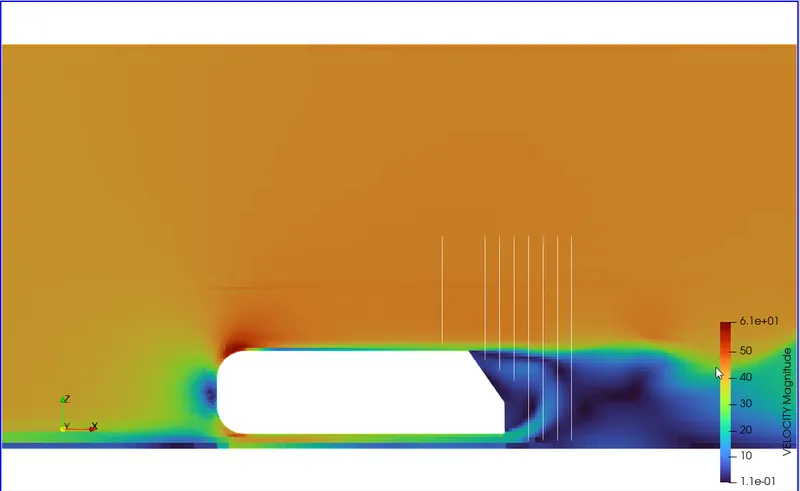
PROBES:
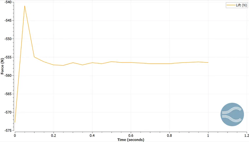
Drag and Lift:
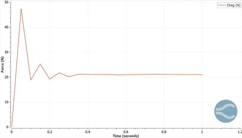
Computing Exact Values of Drag and Lift Forces:
- To compute the drag and lift forces, we will first use the Extract Block filter from Paraview and extract Ahmed's Body boundary
- Then, Extract the Surface from Ahmed's Body using the Extract Surface filter.
- Generate the Surface Normals using the Generate Surface Normals filter.
- Now we have normal components available; we can calculate Drag force by multiplying Pressure with X-Normals and Lift by Z-normals using the calculator filter:
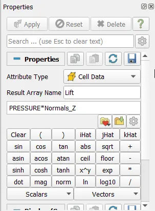
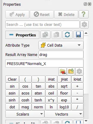
Once We have calculated both values, we can use Integrate Variables filter to calculate the total drag force and lift:


Since we also have the area from the filter, we can calculate the lift/drag coefficients:
`C_(d"/"l) = (2*F_(d"/"l))/(rho*A*V^2)`
`rho =1.225` `kg"/"m^3` (Air at `25^o` C), A = 0.746888 `m^2`
`C_d = 0.02862`
`C_L = -0.7603`
CONCLUSIONS:
- We see that the results are well within a 5% margin away from the Ahmed Body but deviate by varied values while near it. This could result from low mesh resolution near the wall and the inability to capture the y+ effects effectively. A more refined mesh at the walls could produce more accurate results.
- The general observations align with the experimental ones; we see a wake region just behind Ahmed's body, creating the recirculation region.
- A negative lift is observed, which is fine for Ahmed's Body. However, the high magnitude can be attributed to the coarse mesh present under the Ahmed Body resulting from the edge of the embedded refined mesh box.
REFERENCES:
- Ahmed, Syed R., G. Ramm, and Gunter Faltin. "Some salient features of the time-averaged ground vehicle wake." SAE Transactions (1984): 473-503.
- Lienhart, H., C. Stoots, and S. Becker. "Flow and turbulence structures in the wake of a simplified car model (ahmed modell)." New results in numerical and experimental fluid mechanics III. Springer, Berlin, Heidelberg, 2002. 323-330.
- Liu, Yunlong, and Alfred Moser. "Numerical modeling of airflow over the Ahmed body." Proceedings of CFD, Canada (2003): 507-512.