Week 10 - Challenge 3 - Door Trim Lower with Engineering Features
DOOR TRIM LOWER WITH ENGINEERING FEATURES:
OBJECTIVE:
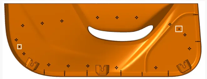
To create the door trim lower from the givel class A surfrace with engineering features (locators & heat stakes) on B side surface.
Given class A surface:
INTRODUCTION:
A car door applique is used in the door pannel to provide an aesthetic look to the door pannel. There are various engineering features in the plastic part. As we know most of the plastic part used in the automobiles are developed from injection molding, we need to design the plastic part for injection molding.
3-2-1 PRINCIPLE:
Most of the OEM's follow the 3-2-1 priciple.A object which is free in space can move infinite number of directions. For analysis, this motion can be broke down into 12 directional movement or 'degrees of fredom'. All 12 degrees of freedom must be restricted to ensure proper referencing of a work piece.
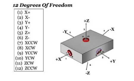
Engineering fearures used to arrest the degrees of freedom:
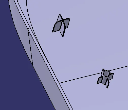
- 4-Way locator
- 2-Way locator
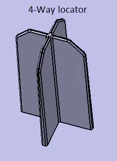
4-Way locator:
A 4-way locator arrest motion along 2 axis or 4 degrees of freedom.
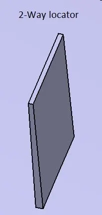
2-Way locator:
A 2-way locating pin arrest motion along 1 axis or 2 degrees of freedom.
Heat stake:
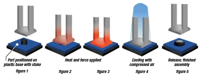
Heat staking is a process utilizes pulsed heat to join two or more parts together where atleast one part is made out of plastic. It workes by heating the plastic part to just above the glass transition temperature while simultaneously applying fore so that it is deformed. It allowed to cool to complete the process.
SEQUENCE OF OPERATION:
- Understanding class A surface
- Creating tooling axis
- Draft analysis for class A surface
- Creating class B surface
- Creating class C surface
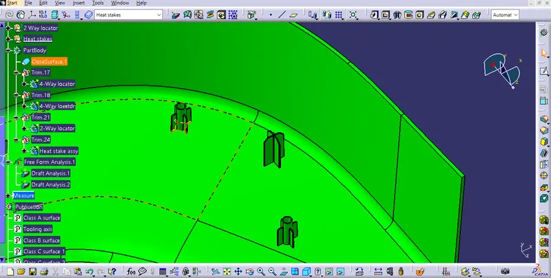
- Adding engineering features to the product
- Draft analysis for the final plastic product
1.) Understanding class A surface:
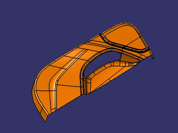
The class A surface is the aesthetic surface which is the visible part to the customers. The class A surface is developed into the plastic product with the engineering features like ribs, screw boss, heat stake etc. are added into it as per the product requirement.
Class A surface:
2.) Creating tooling axis:
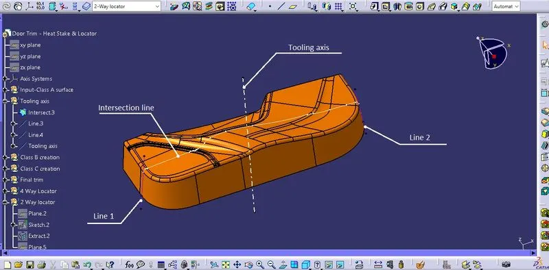
Tooling axis creation is an important aspect for a designer. As it is responsible for the mold (core & cavity) movement. tooling axis should clear the draft analysis. Tooling axis should be ease for manufacturing. Complicated tooling axis can increase the cost and time for manufacturing.
The tooling axis is created by bisecting method
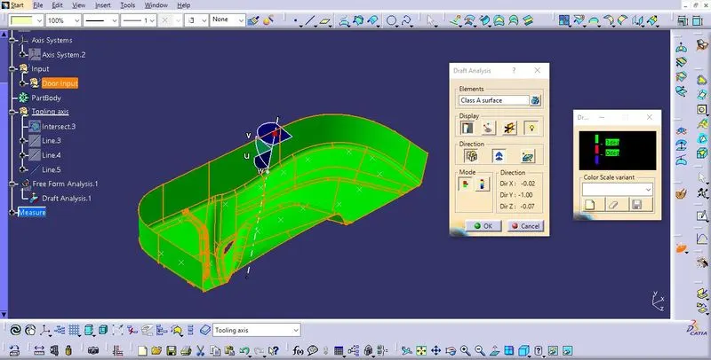
3.) Draft analysis for class A surface:
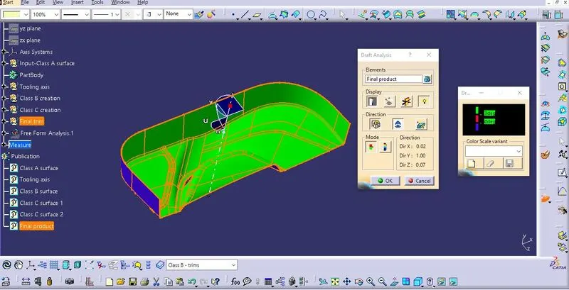
The draft analysis shows draft angle in each surface, the tooling axis should clear the draft analysis.
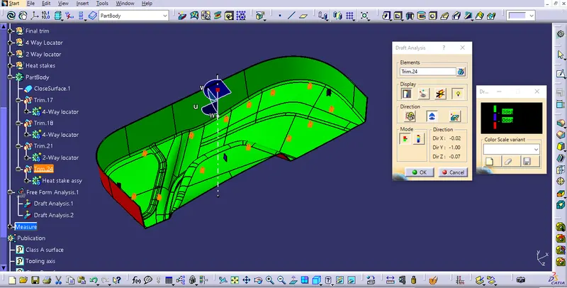
The nominal draft angle is 3°
4.) Class B surface creation:
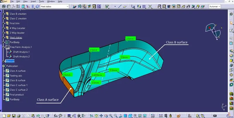
The thickness of the component is 2.5mm
The class B surface is created by offsetting class A surface and minor patches are rectified by using tools like multiple extract, extrapolate, trim, join.
5.) Class C surface creation:
The class C surface is created by using tools like multiple extract, boundary, sweep, extrapolate, trim, join.
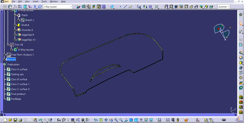
The class C surface is joined with class A surface and trimmed with class B surface to form the final surface and closed boundary condition is checked.
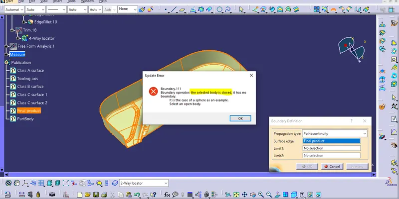
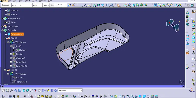
The closed surface is converted to solid part.
Draft analysis for solid body:
6.) Adding engineering features:
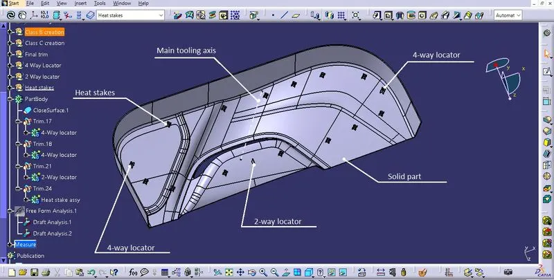
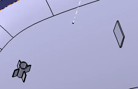
The engineering features added are:
- 4 Way locator
- 2 Way locator
- Heat stakes
The engineering features are added to the B side surface using the design rules
7.) Draft analysis for final component:
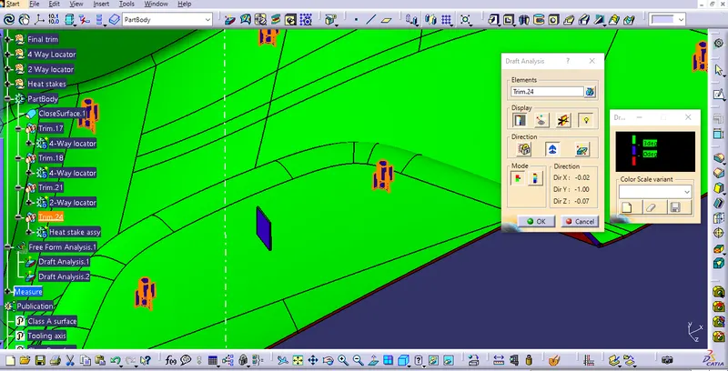
3° draft analysis for the final component:
0.5° draft analysis for the final component:
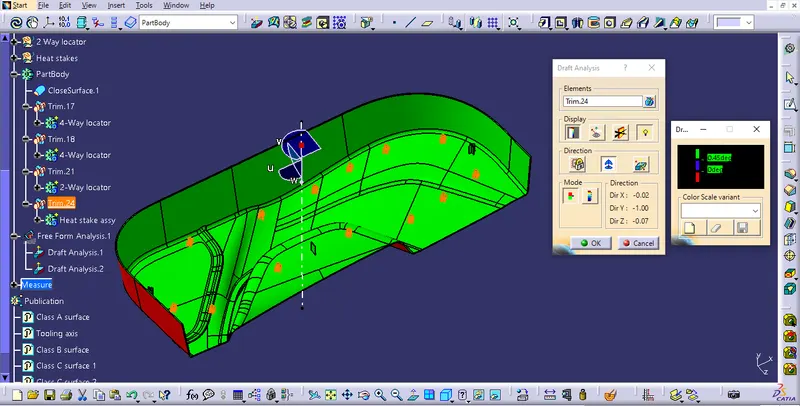
Hence the result shows that the draft analysis are clearing the tooling axis and the component is ready for manufacturing.
Conclusion:
Thus final component is designed and analysed with all the design rules incorporated in it.
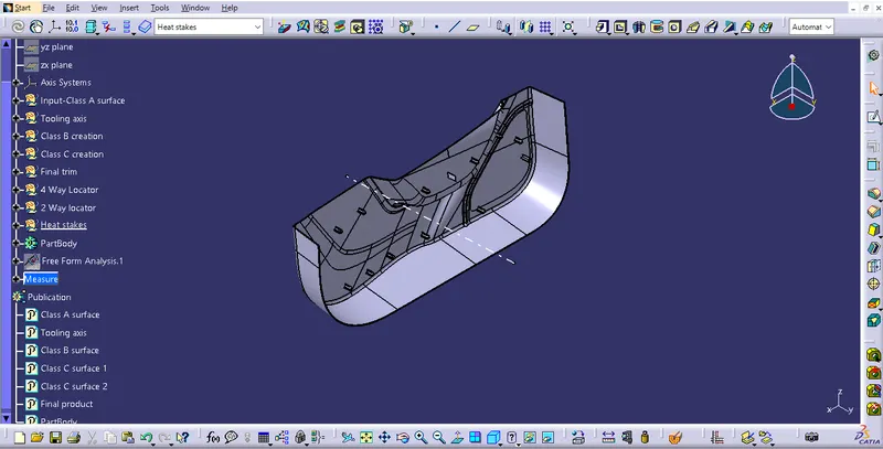
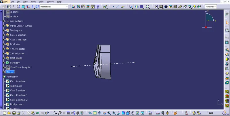
Final component view representation:
Isometric view:
Front view:
Side view:
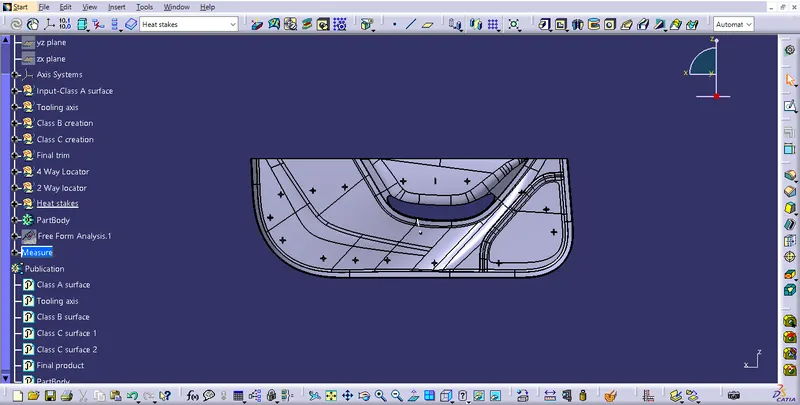
Top view: