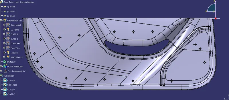
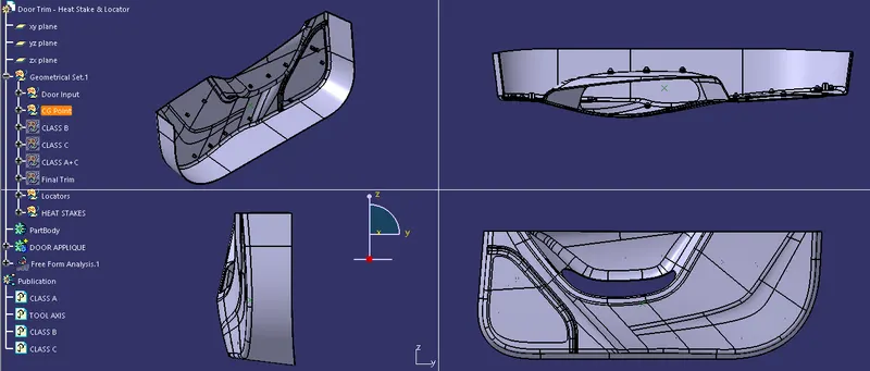
Week 10 - Challenge 3 - Door Trim Lower with Engineering Features
Creation of Tooling Axis
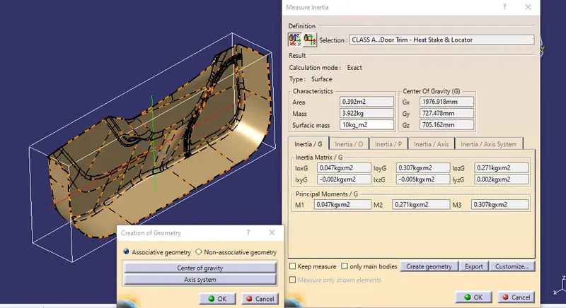
1. Since the part has a compliacted geometry, we will use Measure Inertia method to find the tooling Axis.
2. Click on the Measure Inertia option and choose the Class A surface.
3. Under the create geometry option, Choose non assosiative geometry and choose center of gravity.
4. The center of gravity point is created. Draw a line along Y axis, since the compnent has large flat surface area along Y axis. This line will be our tooling axis.
Draft Analysis
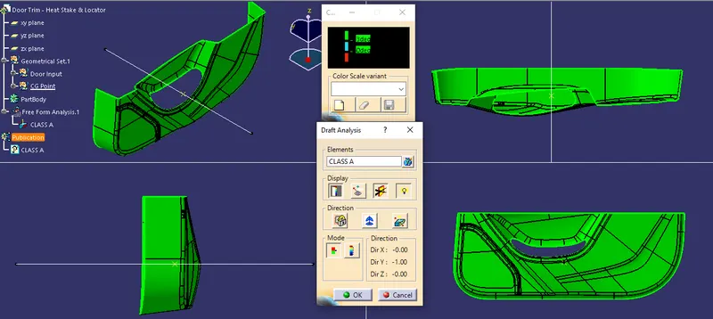
1. Change meshing mode to "material" in the view mode dialog box.
2. Click on draft analysis option.
3. Zoom out and locate the compass, drag and drop the compass to coincide the tool axis to define the new current draft direction.
4. Choose the class A surface/ Solid part to perform draft analysis.
Draft Analysis - Class A
Draft Analysis - Door Applique
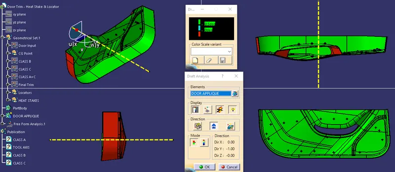
Door Applique With 4 Way locators and Heat Stakes