Week 10 - Challenge 3 - Door Trim Lower with Engineering Features
CHALLENGE- DOOR TRIM LOWER WITH ENGINEERING FEATURES
AIM- Create the door trim lower plastic component through the Given Class A surface. To begin with the tooling axis for the given Class A surface should be created meeting requirements of the draft angle and at the end perform the draft analysis on the model. Create the heat stakes & locators considering the design rules.
OVERVIEW
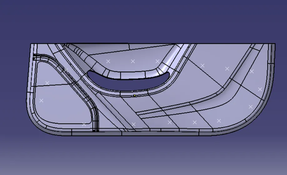
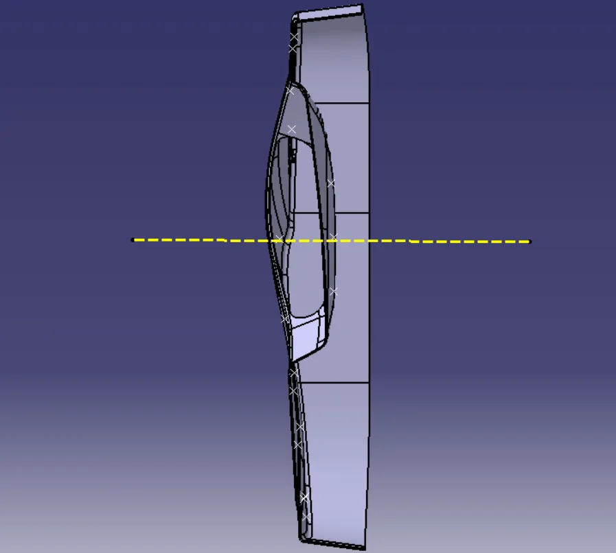
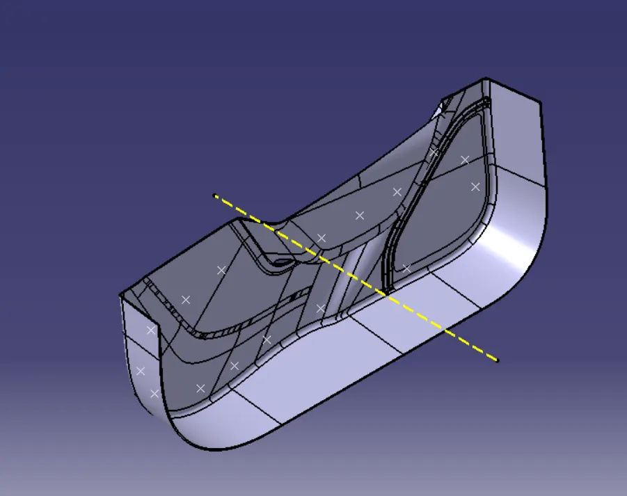
Initially, Class A surface is given of the door trim lower to create Class B surface & Class C surface. First, we need to offset 2.5mm inward direction to Class A surface. After creating Class B surface, there will incomplete patches generated in the surface. Create & complete the patches into single surface by joining the surface through surface command. To join the Class A surface & Class B surface, Class C surface is created by sweep with help of tooling axis to give 3-degree draft angle. After that, join the 3 surface Class A surface, Class B surface & Class C surface by joining through join command. Later change it to solid closed body.
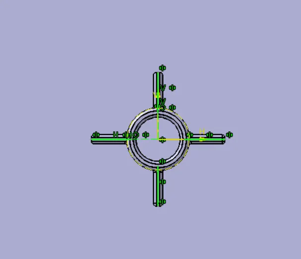
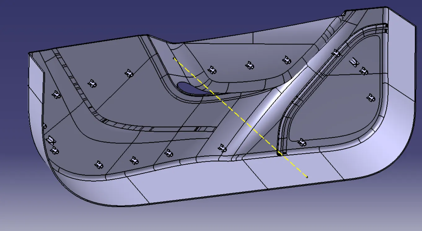
Now Create the Locators & heat stakes to given points in the door trim lower according to the given diagram.
METHODOLOGY
TOOLING AXIS
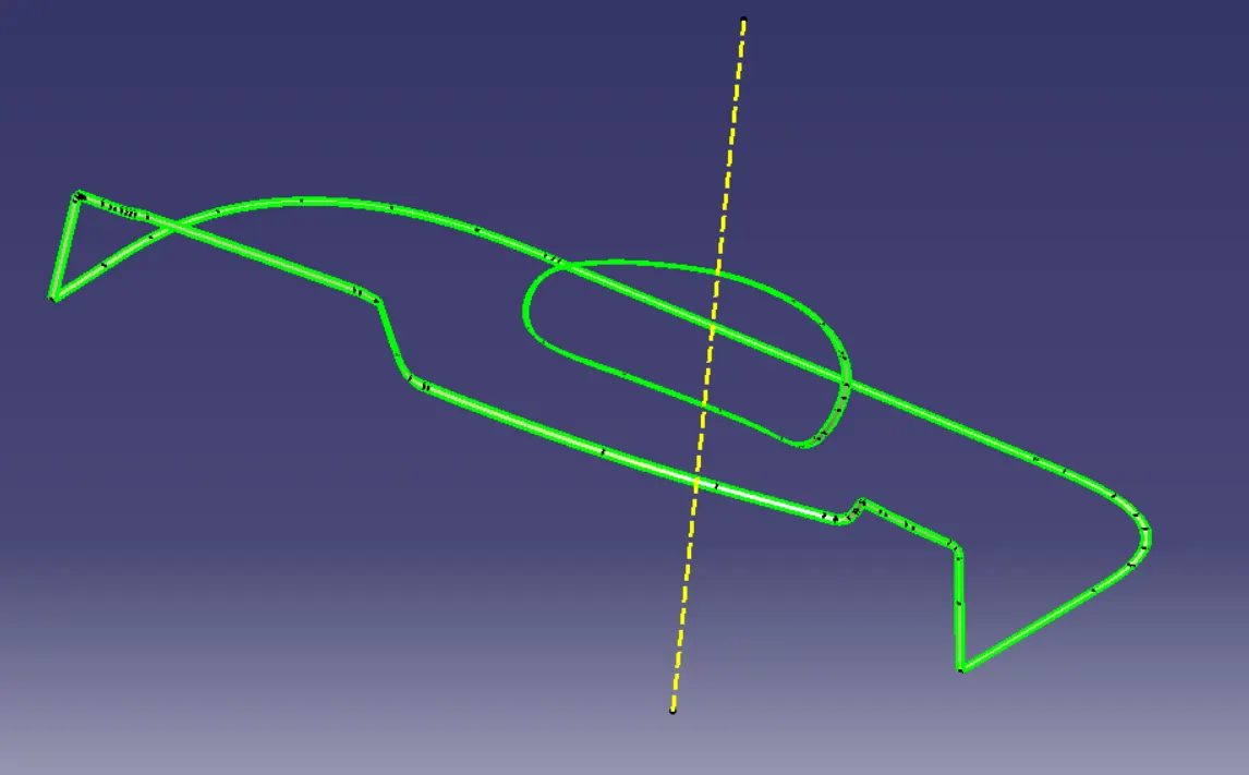
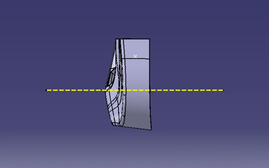
To create tooling axis, first extract the Class A surface & create the mid-point by point commands. Use intersect command to intersect in XY Axis. Now, create to lines from the intersecting line & bisect two line which generate bisecting line known as tooling Axis. So, tooling axis is created & can used in draft analysis & also draft angle of Class C surface.
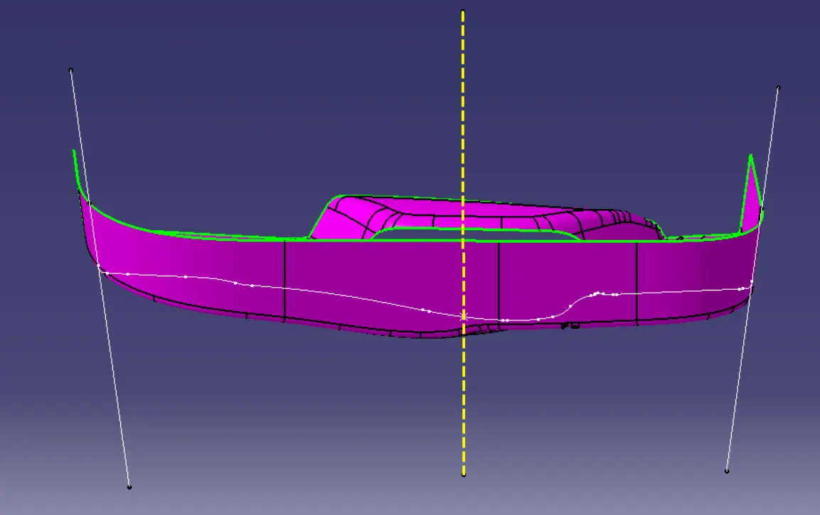
DRAFT ANALYSIS
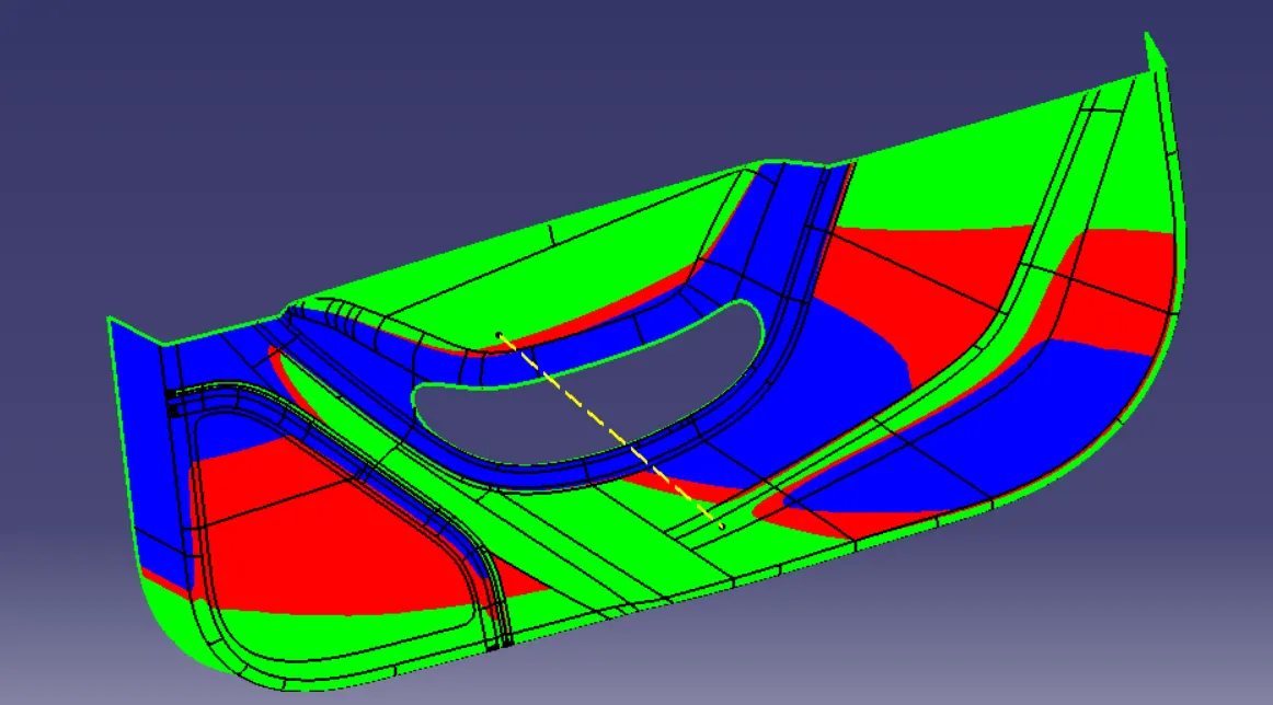
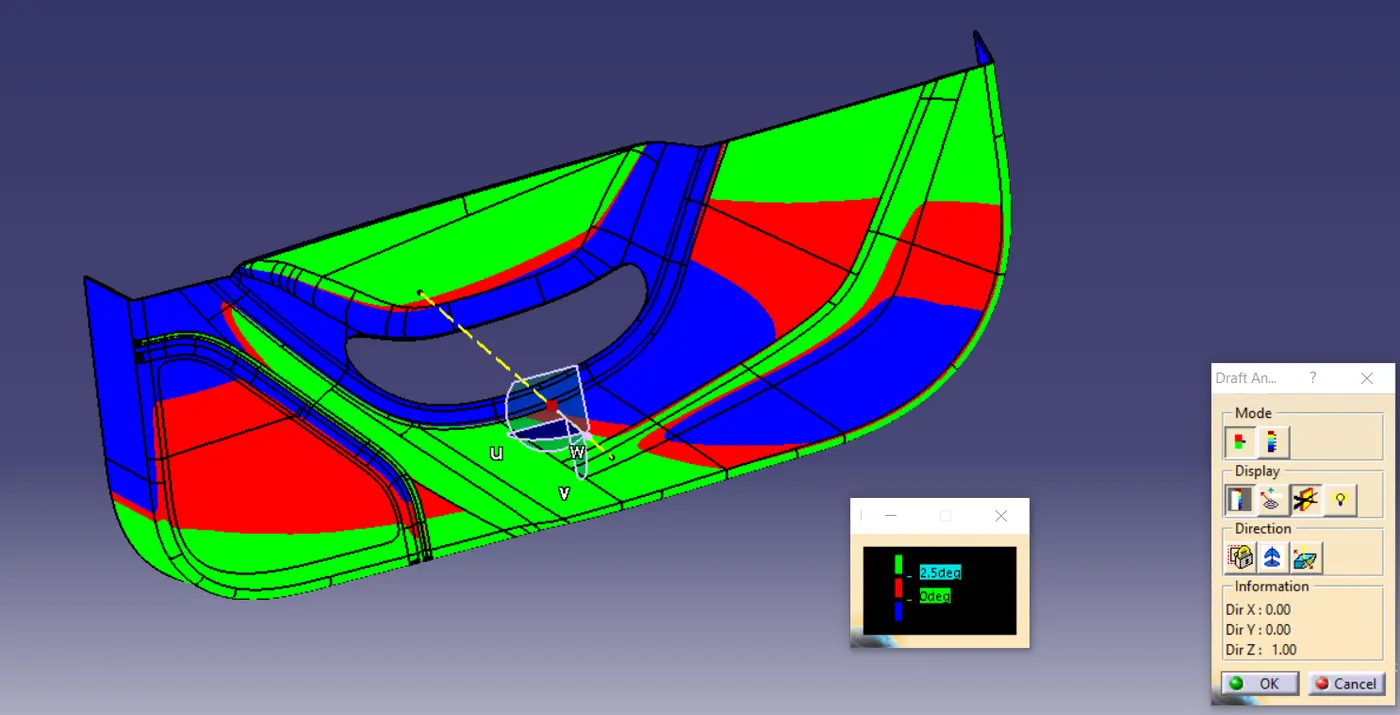
Before, creating Class B surface, we perform the draft analysis on the Class A surface with tooling axis, aligned with compass. According to draft angle colour coding it shows, if the colour is showing green then the draft angle is proper & if not highlight fully green colour, then there might be reason for the draft angle of the Class A surface.
CLASS A SURFACE DRAFT ANALYSIS
CLOSED BODY DRAFT ANALYSIS
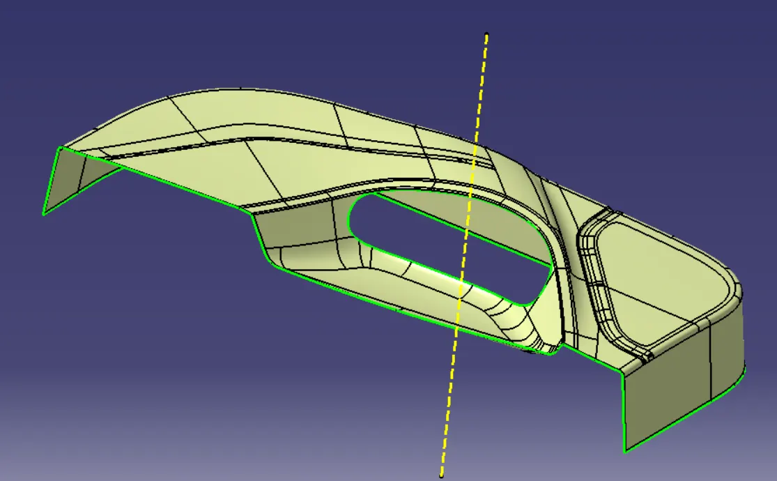
CLASS B SURFACE
First, create offset with the reference of Class A surface inside as per thickness is required (2.5mm). Once the offset is created, we observed that patches in the offset is having gaps. In order to patch the gaps, we need to repair the gaps through multi-sections & through blend commands to fill up the patches. Join the different surface through single surface by joining command as the process is being progress one-by-one. Extrapolate the boundary surface of the Class B surface for next process.
CLASS C SURFACE
Take the boundary of the Class A surface to create the Class C surface. Go to sweep command, select with refence surface.
If the generated C surface is parallel to the tooling axis create the sweep along the draft direction at angle of 3 degree.
If the surface is perpendicular to the tooling axis, then create the sweep using the reference surface option then extrapolate the connecting surface & trim the surface together & join them all together to form the Class C surface.
Now, join the class A surface with class C surface
PART BODY
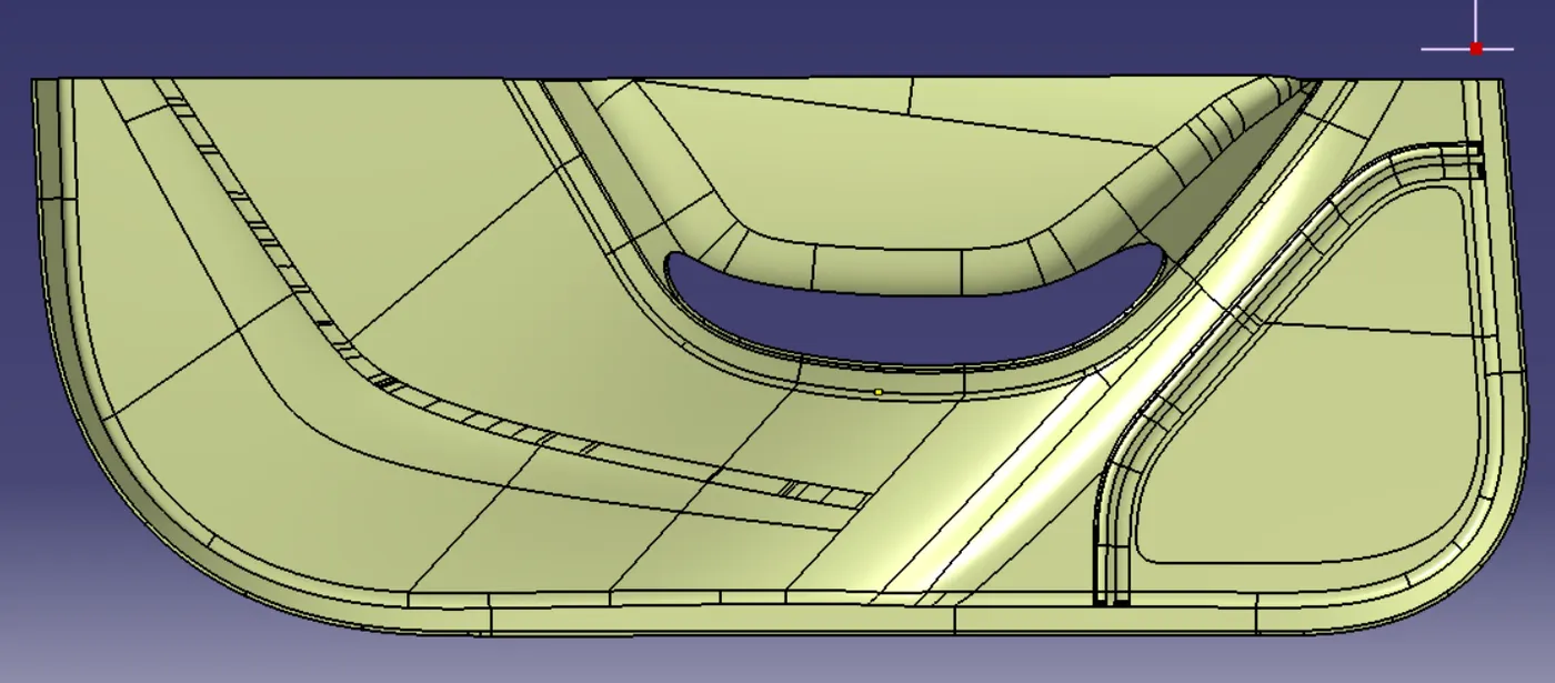
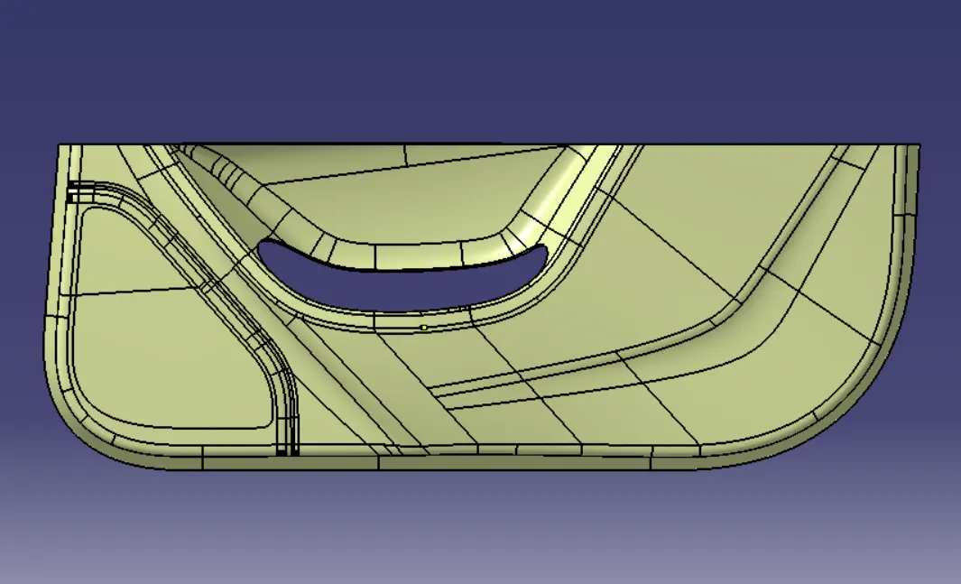
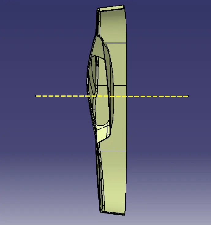
To create the solid part body from the closed surface, we used the closed surface command in the part workbench.
LOCATOR CREATION
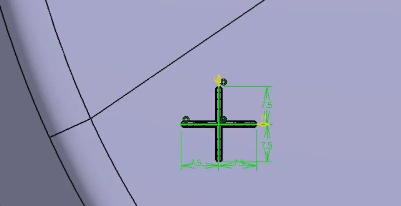
HEAT STAKES
FINAL BODY
CONCLUSION
The given challenge has been done with given detail completed successfully.