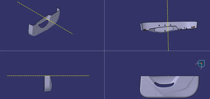
Week 10 - Challenge 3 - Door Trim Lower with Engineering Features
AIM: The objective of this project is
- To create the Door Trim closed component from the given Class-A surface.
- To create the tooling axis for the given Class-A Surface meeting the requirements of the draft angle.
- To create Engineering Features ( HEAT STACK & FOUR WAY LOCATOR) on the B side surface considering the design rules for that.
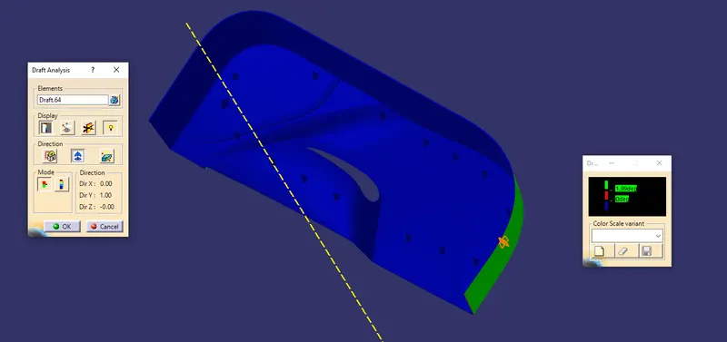
- To perform the Draft analysis on the Final component.
STEP 1
CLASS A SURFACE
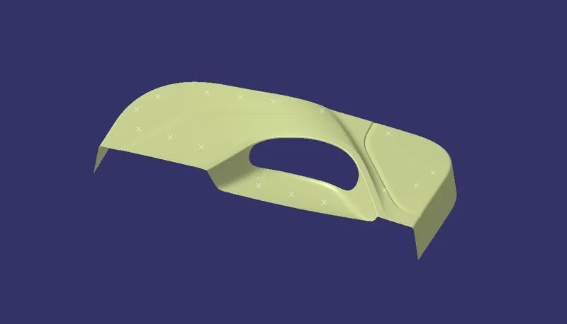
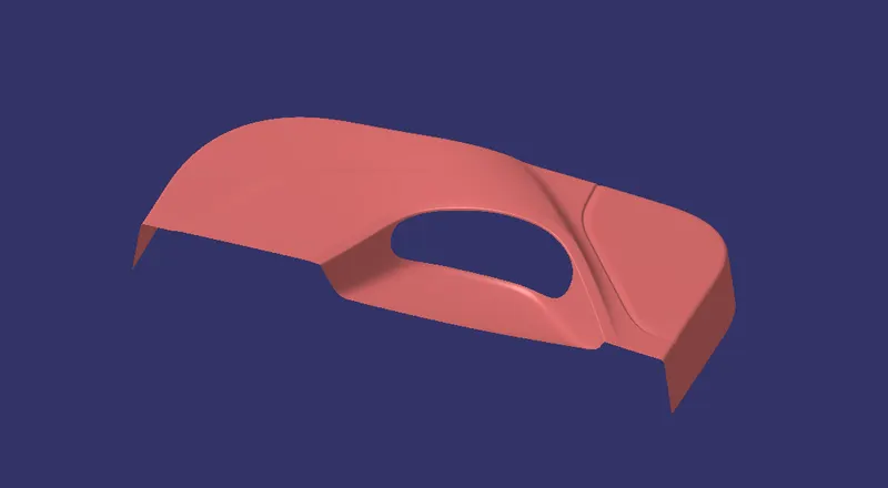
- Open the class A surface and join all the surfaces using Join feature.
- Use boundary on the class A surface to check the connectivity.
STEP 2
TOOLING AXIS
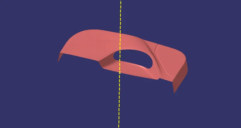
- Create a point on the class A surface and create a line with reference to that point and the respective direction on the compass.

STEP 3
DRAFT ANALYSIS ON CLASS A SURFACE
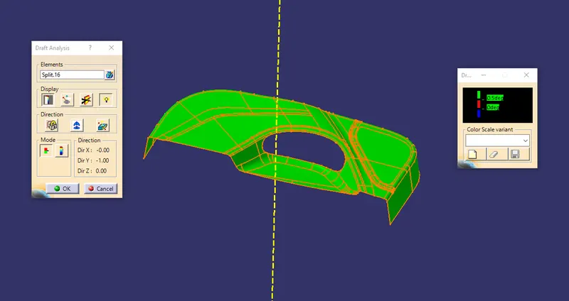
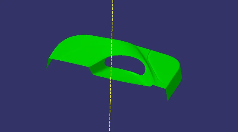
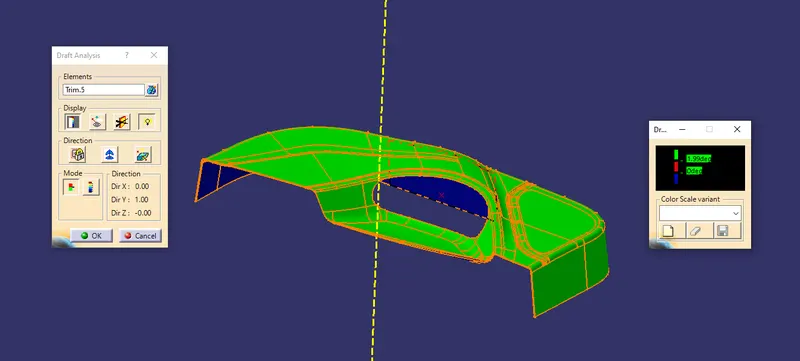
- Use Feature Draft Analysis on the class A surface by aligning the compass to the tooling axis and select the A surface as the element and then click Ok.
STEP 4
CLASS B SURFACE
- Use offset feature to offset the class A surface of about 2.5 mm.
- Use Extract and Multiple Surface Section to repair the gaps on the class B surface.
- Otherwise, use Blend feature if Multi surface sectioin is not coming correct. After repairing the Class B surface , extrapolate the surface by using Extrapolate feature.
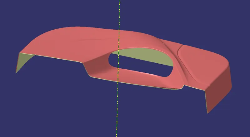
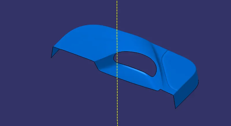
- Offseted B surface with repair work.
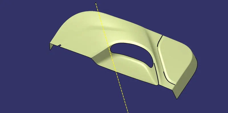
- Final Class B Surface after repairing and extrapolating.
STEP 5
CLASS C SURFACE
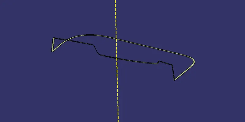
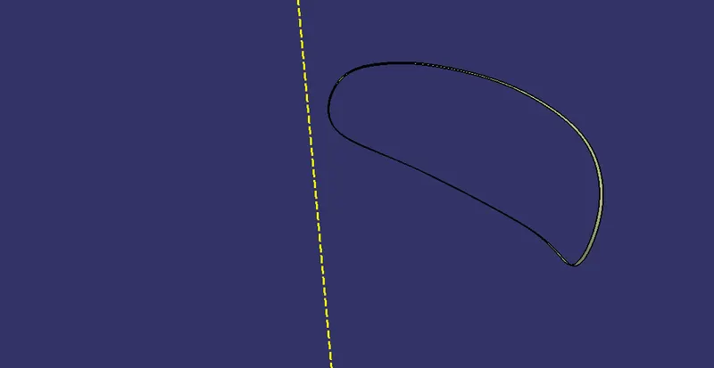
- Create a boundary on the Class A Surface using Boundary feature or Curve smooth feature. And then use Sweep option to the boundary to create a sweep surface with an required draft angle. If the sweep came properly without any twist and turns or any sharp edges, then its fine. Otherwise we need to sweep seperately from the class A surface using sweep and multiple surface section.
- After doing that, join all the sweeped surfaces using Join feature.
STEP 6
CLOSED SURFACE
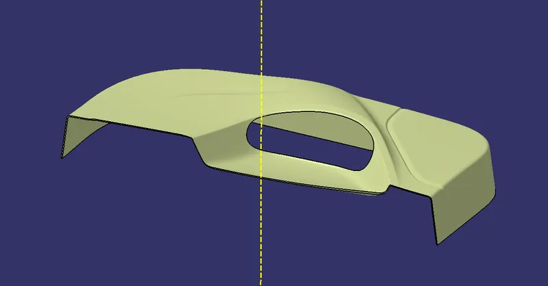
- First, join the Class A Surface with Sweeped Class C Surface by uising Join Feature. Then, use Trim feature to trim the joined surfaces with the class B surface.Thus the closed surface is completed.
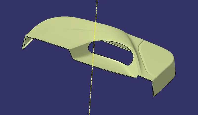
- Final Closed surface.
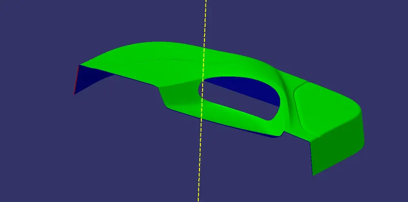
- Draft analysis on closed surface.
STEP 7
B SIDE FEATURE CREATION
HEAT STACK CREATION
- First, create a reference plane on the B surface and draw the profile for heat stack.
- Use Pad option on part design to the sktech and pad it ti the height of about 20 mm.
- Now, use draft on the padded surface with an draft angle of about 0.5 degree.
- Then, draw a cross section lines of about 15 mm each for making the ribs for heat stack.
- Again use Pad to the sketch and use draft on it.
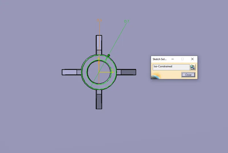
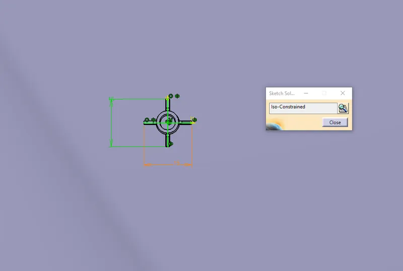
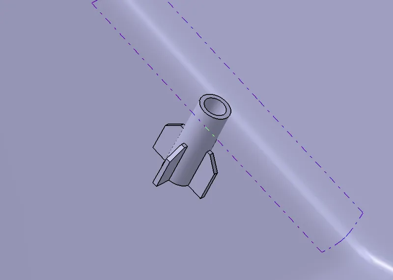
FOUR WAY LOCATOR
- Create a cross secting line of about 15 mmm each and symmetry it to the axis.
- Use Pad to the sketch of height 20 mm. And use draft on it with an angle of about 0.5 degree.
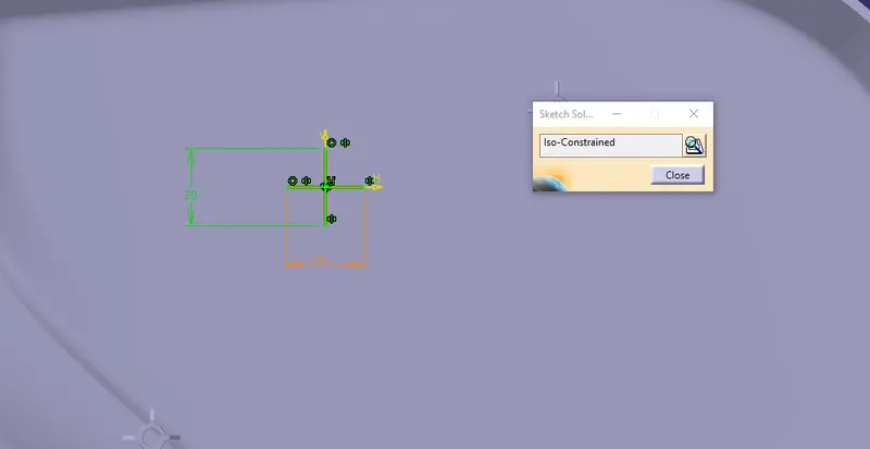
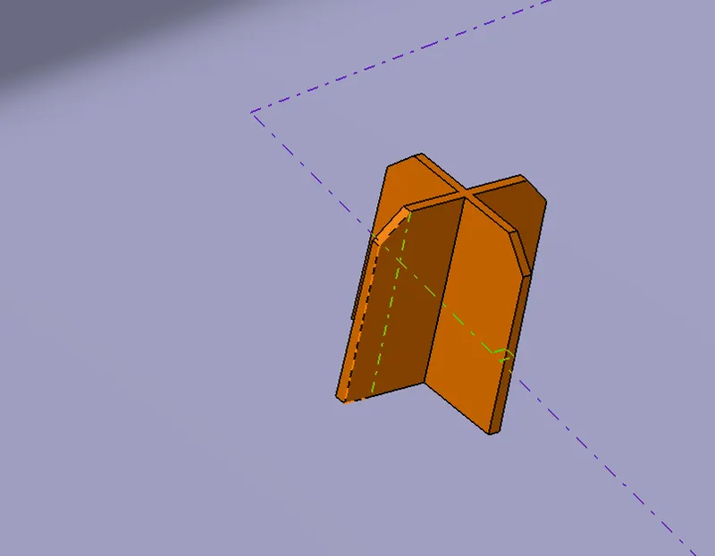
Finally, add all the engineering features to the solid component and use draft analysis to the final component.
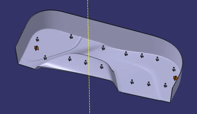
- SOLID COMPONENT
- Draft analysis on final solid component.
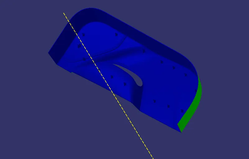
- MULTI VIEW