Week 10 - Challenge 3 - Door Trim Lower with Engineering Features
DESIGN OF DOOR TRIM LOWER WITH ENGINEERING FEATURES
10/18/2023
Shanil kumar K S
OBJECTIVE
The primary objective of this task is to generate a 'Door Trim Lower' solid body utilizing the closed surface technique through the 'Generative Shape Design' workbench in CATIA V5. Additionally, conducting a 'Draft Analysis' on the solid part body of the door trim is required.
OVERVIEW
To begin, we must offset the provided Door Trim Class A surface inward to achieve the desired thickness (in this case, 2.5mm). Subsequently, the patches on the Door trim's offset surface, resulting from the fillets on the Class A surface, must be closed. Once all patches are appropriately closed, they should be merged to create a refined Class B surface. Next, the boundary of the Class A surface needs to be swept to intersect with the Class B surface, forming a unified, enclosed body. Employing the closed body command in the Part workbench allows for the creation of a solid body from the Door Trim's closed surface.
Following this, I designed the Heat Stakes and Locators, taking all design parameters into consideration. With all B-side features established on the solid part body of the door trim, a draft analysis was conducted to ensure proper drafting of all surfaces (with the plastic component's draft angle ranging from 0.5 degrees to 3 degrees).
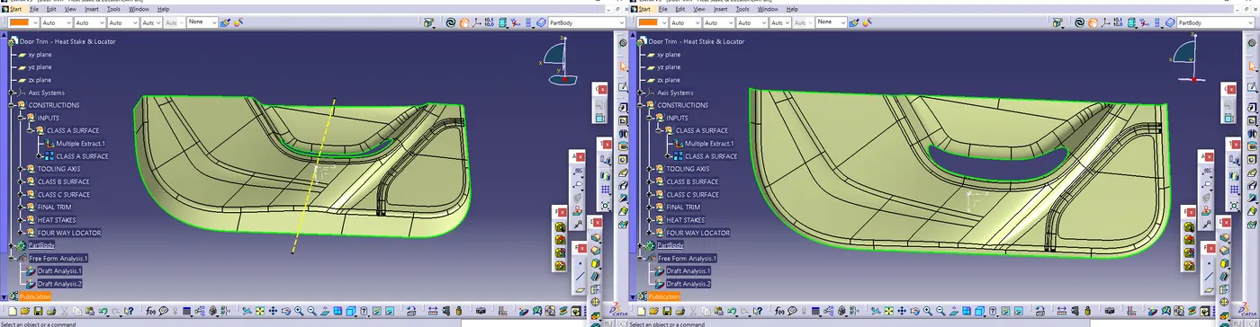
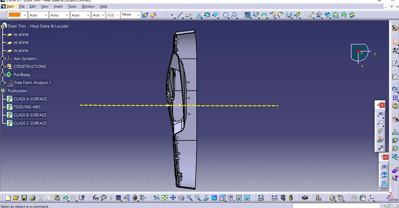
TOOLING AXIS
The tooling axis was established using the Bisecting method. A reference plane was created, bisecting the component symmetrically along its centerline. This ensures an effective and balanced mold release during the manufacturing process.
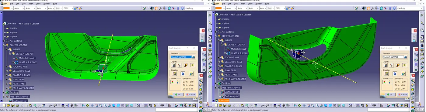
DRAFT ANALYSS FOR CLASS A SURFACE
Apply the draft analysis tool in CATIA V5 software to the Class-A surface and the tooling axis created. Ensuring that the draft angle meets the specified requirements (usually based on manufacturing and ejection considerations).
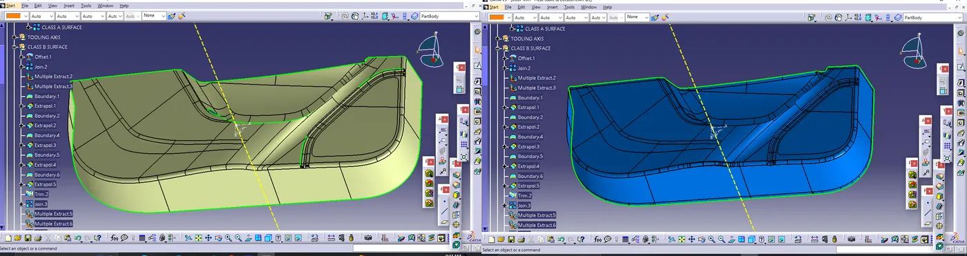
CLASS B SURFACE
In order to generate the Class B surface, I performed an inside offset of the Class A surface, adhering to our specified thickness requirement (in this instance, the offset was set to 2.5mm). Following the creation of the offset, certain patches were observed on the offset surface as a result of the fillets present on the Class A surface. To address this, the multi-section surfaces command was employed to encompass these patches by extracting their boundaries. Once all the patches on the offset were adequately covered, I merged them with the offset surface, resulting in a replicated surface of the Class A surface.
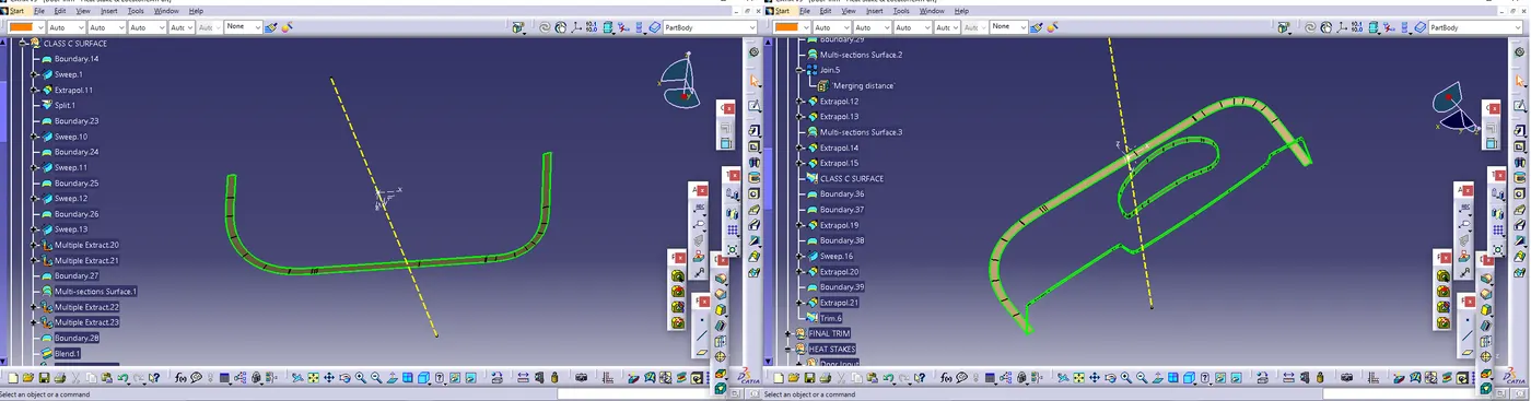
CLASS C SURFACE
Class B and Class C Surfaces were seamlessly integrated into the design, aligning perfectly with the Class A Surface. Surface quality was prioritized to ensure a smooth, high-quality finish.The class c is jioned with A and trimmed with B to form a closed surface.
PART BODY
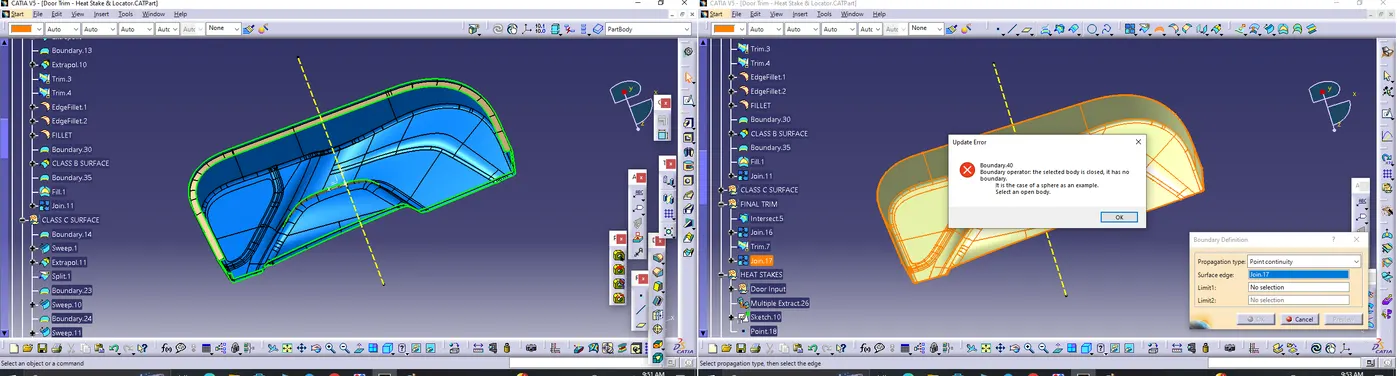
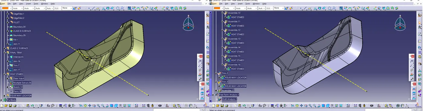
Inside the "PART BODY" , the "Close Surface" feature was used to generate a solid body from the Class-A surface, ensuring a consistent thickness.
Close surface :-
Solid body:-
CREATION OF LOCATORS
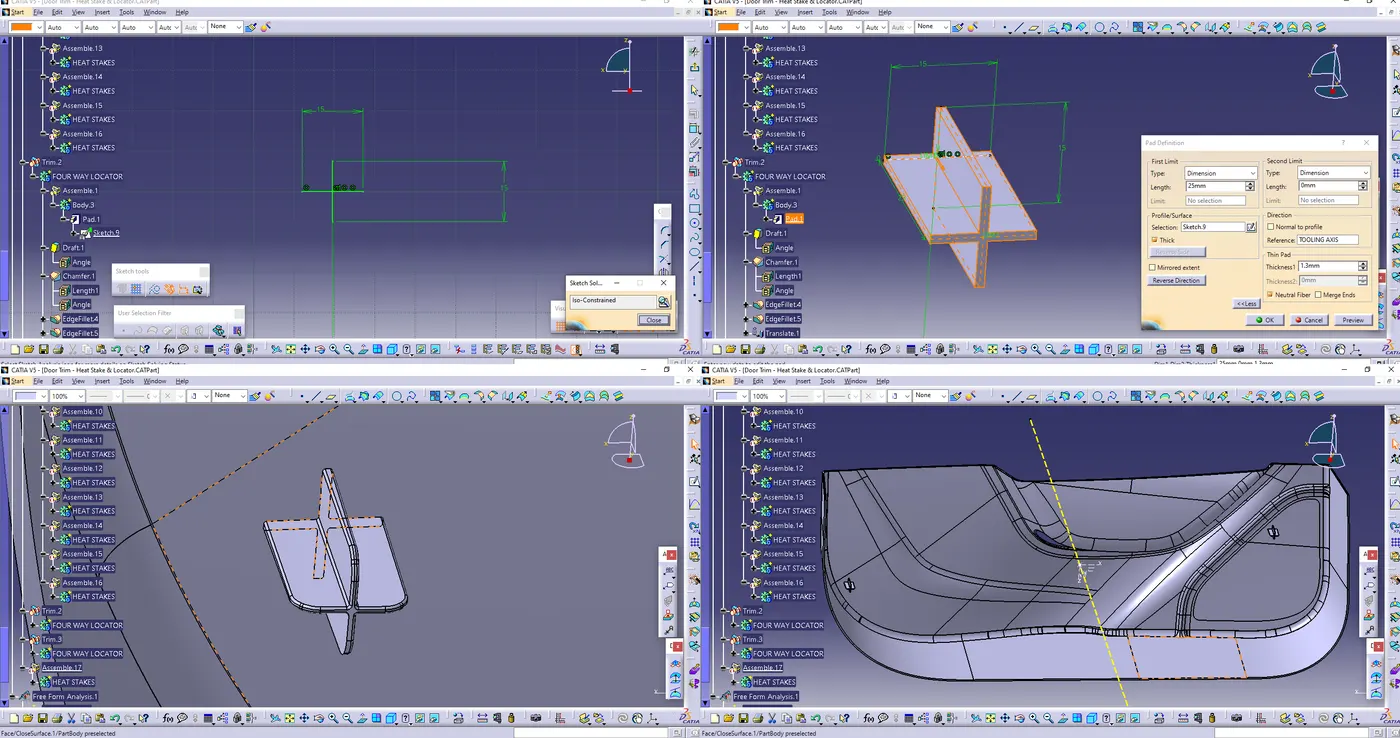
For the creation of the locators, I first generated a sketch on the body. Subsequently, I extended the sketch by 25mm in height using the pad feature and applied a thickness of 1.3mm. I then implemented a 0.5-degree draft in the direction of the tooling axis. Following this, I added a 3mm chamfer with a 45-degree inclination. Finally, I applied a 0.3mm radius fillet to the design.
CREATION OF HEAT STAKES
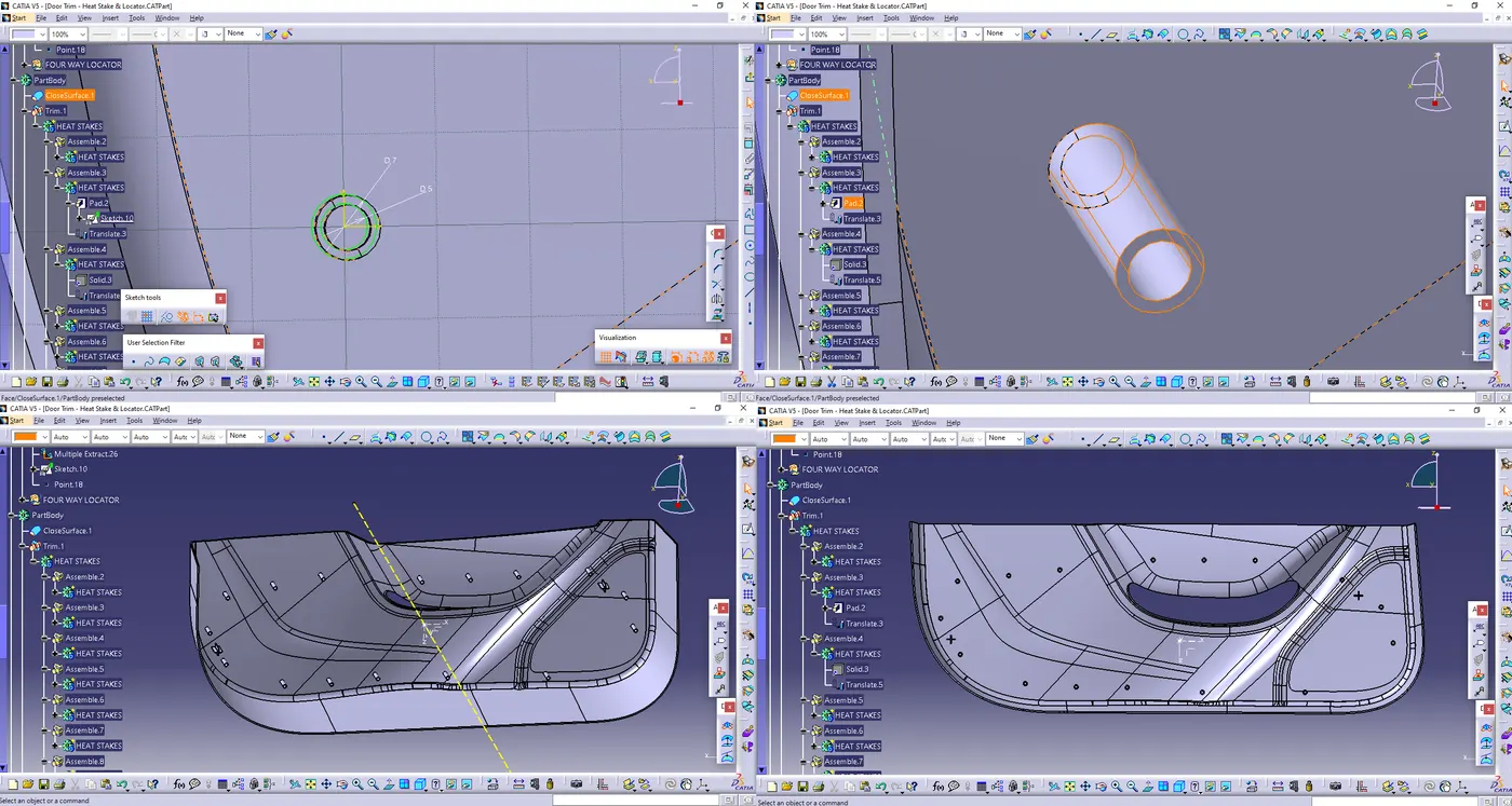
To generate the heat stakes, I began by sketching on the surface. Once the sketch was complete, I extended it to a height of 15mm using the pad feature. I applied a 0.5-degree draft on both the inside and outside. Following this, I added a fillet with a radius of 0.25mm.
DRAFT ANALYSIS OF FINAL PART:-
The draft angles throughout the Door trim component were carefully reviewed. It was observed that the draft angles consistently met the specified requirements of 3 degree. This ensures that the component can be easily removed from the mold during manufacturing.
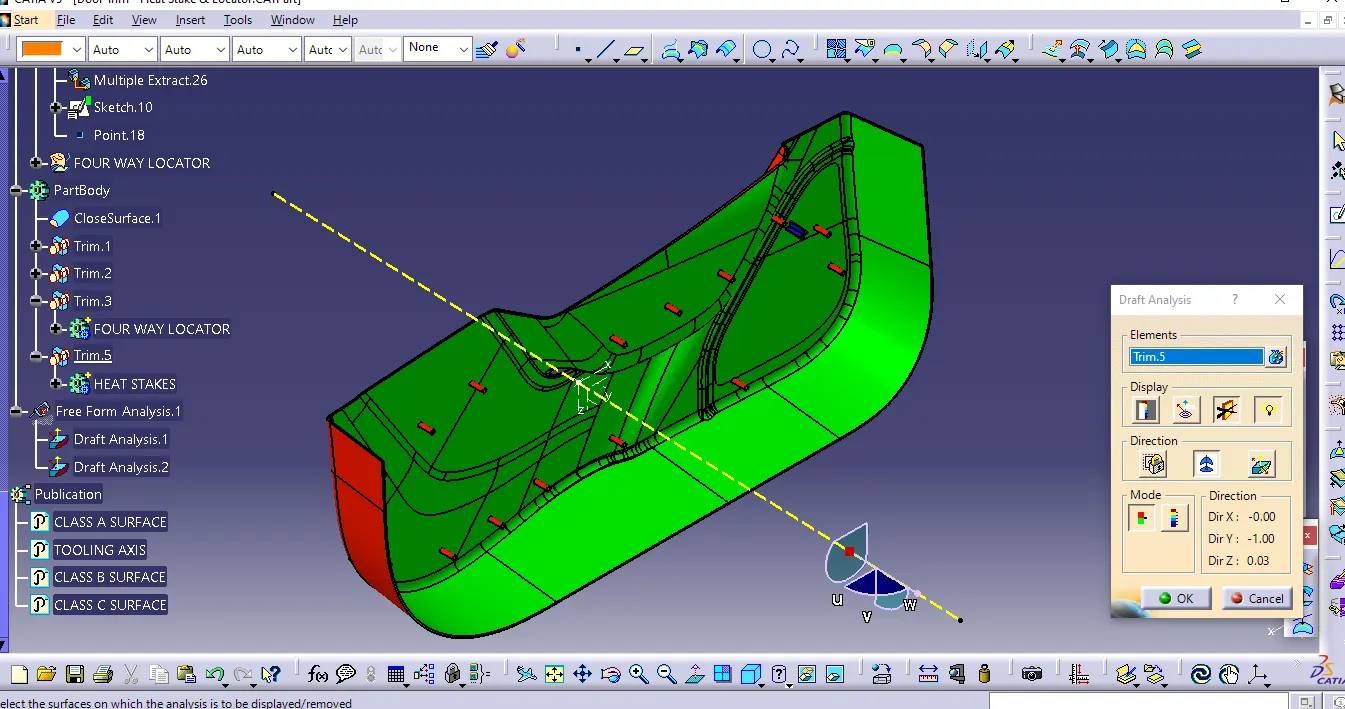
- Screenshots of the solid model with the proper color code of the draft angle in various orientations (Isometric, Front, Side, and Top View)
- ISOMETRIC VIEW
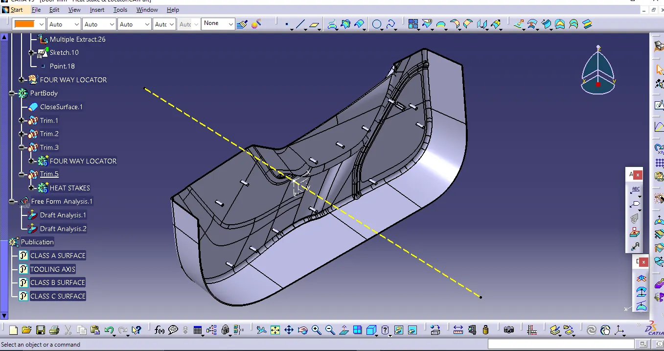
- FRONT VIEW
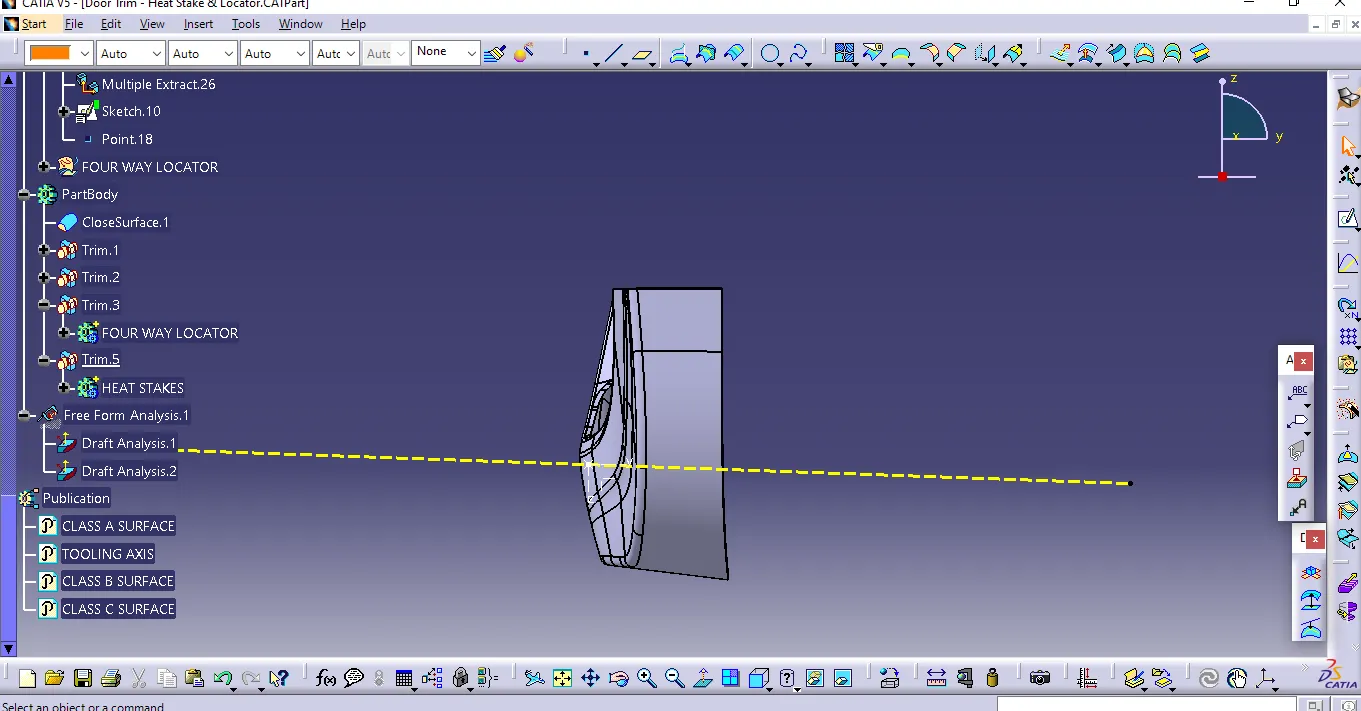
- SIDE VIEW
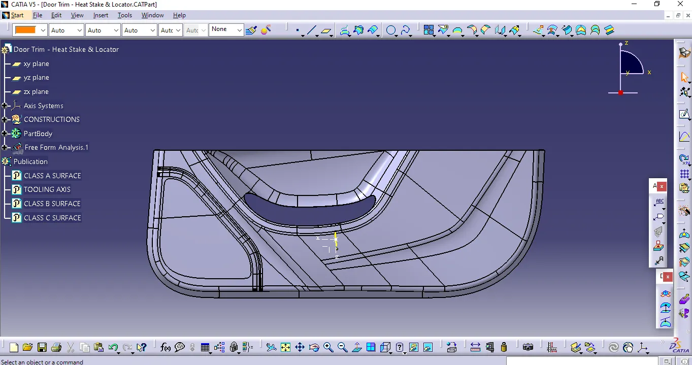
- TOP VIEW
- Expanded Specification Tree (after completion of all steps):
SPECIFICATIONS
The parts are drawed with the following specifications
length = mm
angle = degree
time = seconds
CONCLUTION
The Heat stakes and four way locator design adheres to specifications, ensuring structural integrity and effective functionality for the Door Trim. The application of the Bisecting method for the tooling axis guarantees efficient manufacturing and reliable mold release. Overall, it meets quality standards and enhances the Door Trim's performance.