Week 10 - Challenge 3 - Door Trim Lower with Engineering Features
1)
AIM:
- Create the Door trim Plastic component through the given Class-A surface. To begin with, the tooling axis for the given Class A Surface should be created meeting the requirements of the draft angle and at the end perform the Draft analysis on the model.
- To Create the rib and screw bosses for the Door Trim Lower considering the design rules.
- To Create the Heat stakes and locators considering the design rules.
- To Create the Dog house considering the design rules.
CLASS A SURFACE
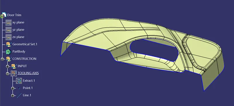
- Check the connectivity of the Class A Surface
- Ensure that there is no gap between the component, using join command.
- We can visually check it or by clicking boundary command.
- Therefore first check completed.
TOOLING AXIS CREATION
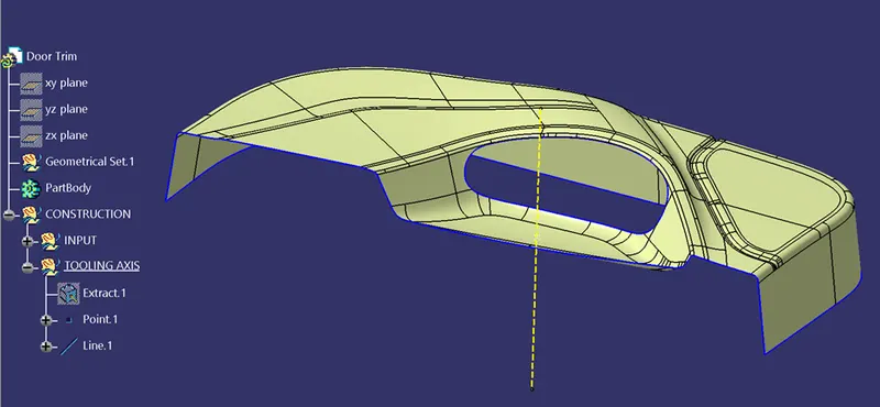
- Find the tooling axis of the component.
- The tooling axis is nothing but the mould opens or cavity opens.
- Check visaully which is the best possible tooling axis.
- Check all three axis.
- Now perform the Draft analysis using the Featured Draft Analysis tool in the tools.
- Then after opening the draft analysis tool box go for the compass and place the compass alinged to tooling axis and click on the lock symbol after alinging and further click on the surface.
BISECTING METHOD
- Bisecting method is basically use to find the proper tooling axis using the dummy tooling axis.
- In Bisecting method, bisecting line is used which either bisect the two line or it will show error which means the two lines are parallel to each other.
- In order to know whether the particular surface is toolable or not we intersect the surface with the respective plane and get a sketch which consist of two lines and with the help of bisecting line option we bisect the line which creates a line at the mid point of the two lines.
- Like wise we create tooling clearing axis for x and y which will be used to create the main tooling axis using the bisecting line option in in the line comand.
DRAFT ANALYSIS ON CLASS A SURFACE
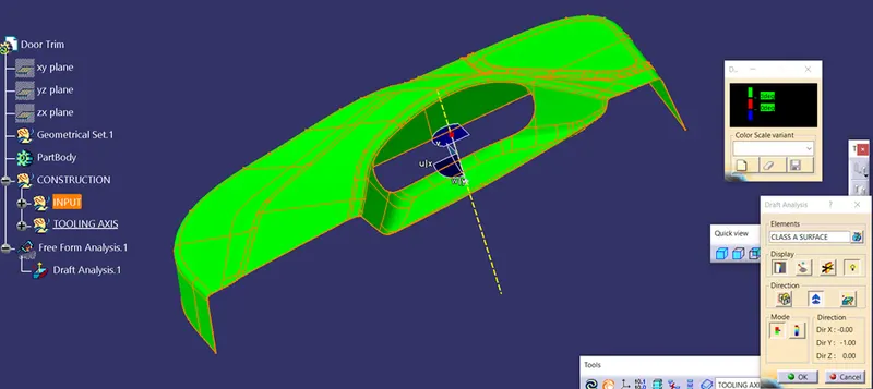
- Go to insert< analysis< feature draft analysis.
- Align the tooling axis with the compass.
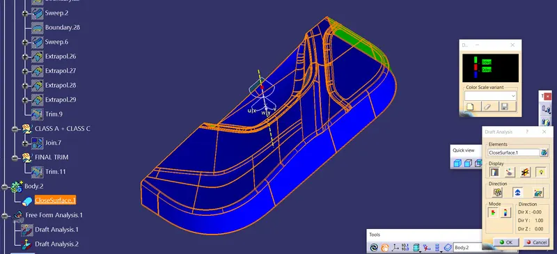
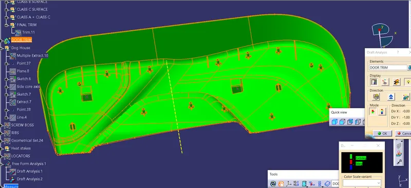
- Click on the surface and see that the surface is within the permissible limit of the draft values.
- The surface should be green and in the column proper value (3deg) should be inserted.
OFFSETTED CLASS B SUFACE WITH COMPLETING PATCH OPERATIONS
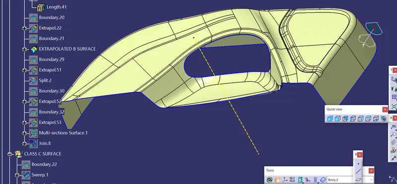
- Offset the class a surface 2.5mm direclty.
- Some patches will form after offsetting.
- Remove the filleted region for closing the patches.
- Define the boundary and extrapolate to required length.
- Now trim the surfaces to required surfaces
- Now provide proper fillet the surface to required amount
SWEEPED CLASS C SURFACE
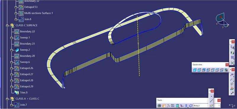
- Extract the boundary of the class-A surface.
- Extract the boundary of the holes on the class-A surface.
- Use sweep command on the boundaries one by one to get the class-C surface.
JOINED CLASS C SURFACE AND CLASS A SURFACE
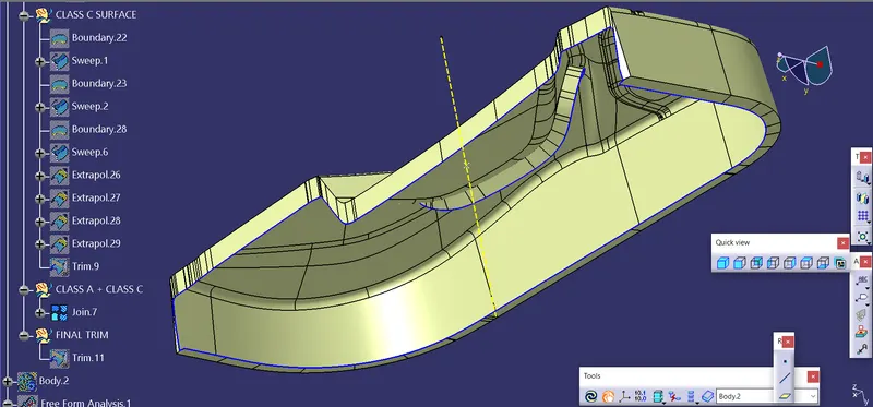
- Join the class-A and class-C surfaces together
- Trim the class-B surface with the join created earlier.
DEVELOPED PLASTIC BODY FOR DOOR TRIM
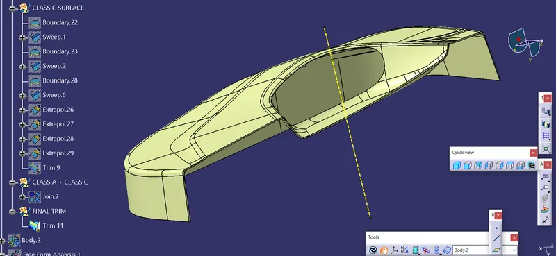
DOOR TRIM CLOSED SURFACE
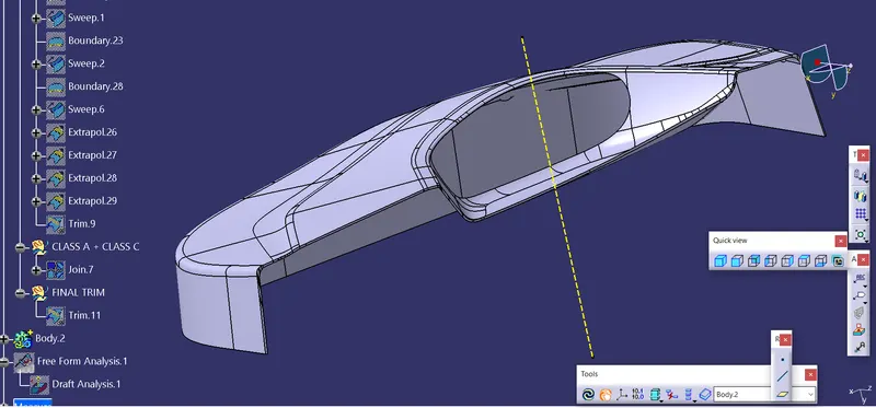
DRAFT ANALYSIS ON CLOSED SURFACE
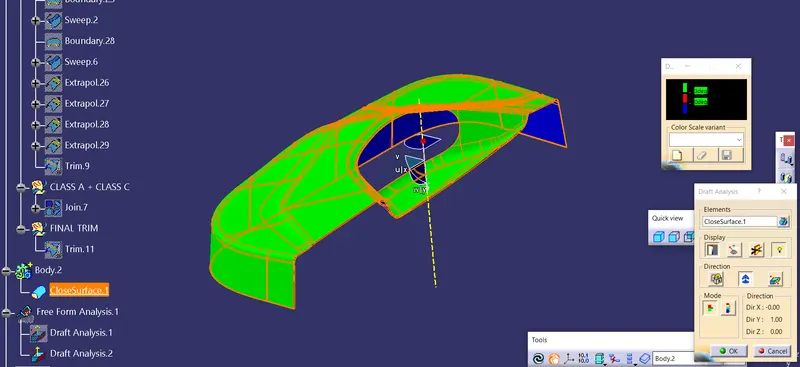
DRAFT ANALYSIS ON CLOSED SURFACE
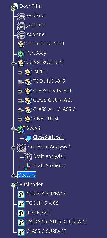
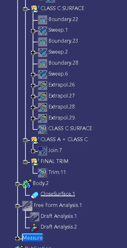
DESIGN TREE STRUCTURE
EXPANDED DESIGN TREE STRUCTURE
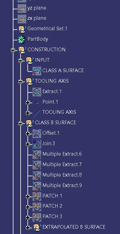
EXPANDED DESIGN TREE STRUCTURE
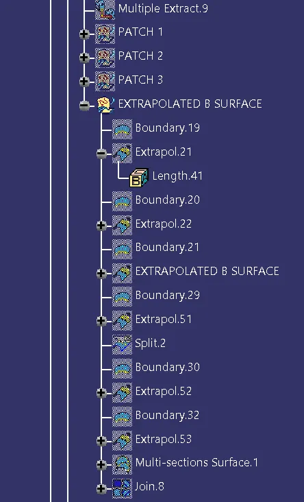
EXPANDED DESIGN TREE STRUCTURE
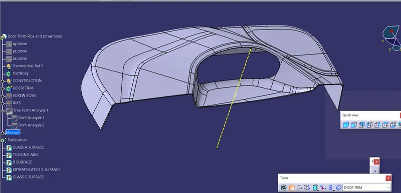
DEVELOPED SOLID BODY
RIBS DESIGN CONSIDERATIONS
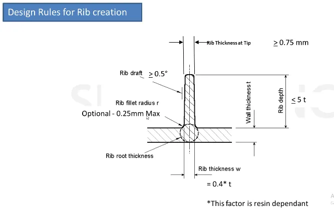
- Consider the nominal thickness of plastic body is t.
- The base width of the ribs lies between 0.3t to 0.7t.
- The rib height should be less than 5t.
- Spacing between the ribs should more than 4t.
- Radius at base of rib is (t/0.8).
- The draft angle between 0.5 to 2 degrees.
CREATED RIBS BEFORE ASSEMBLING AND UNION TRIMMING
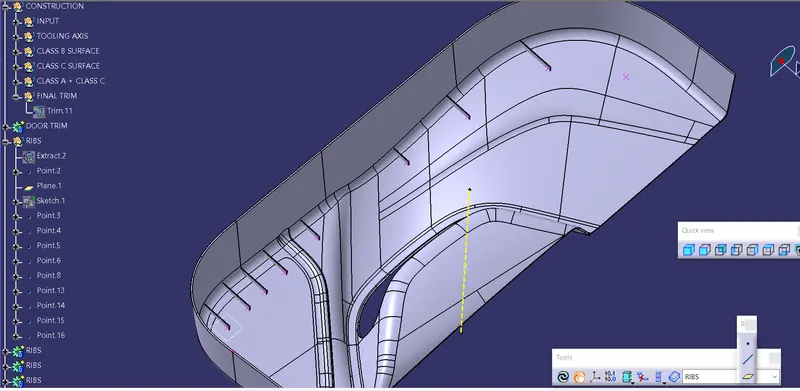
CREATED RIBS BEFORE ASSEMBLING AND UNION TRIMMING
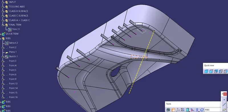
DESIGN VERIFICATION
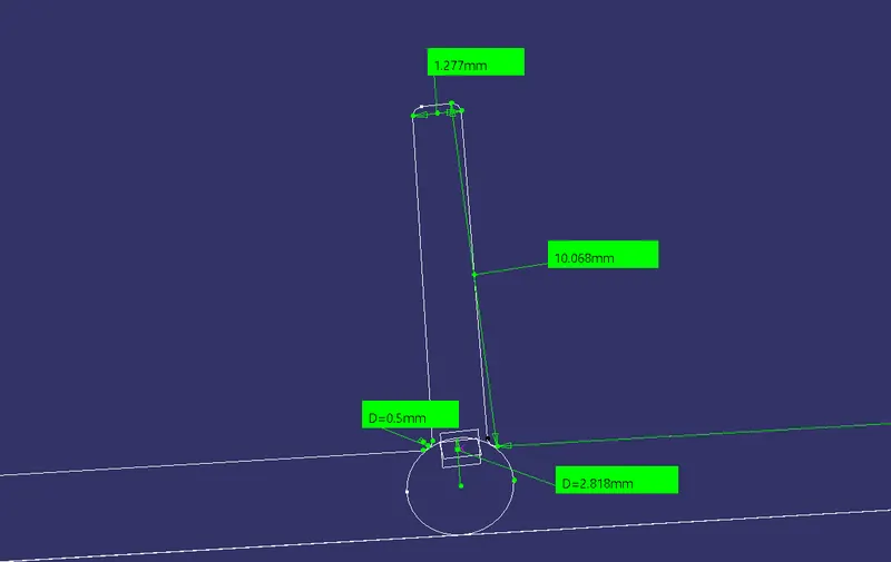
DESIGN VERIFICATION
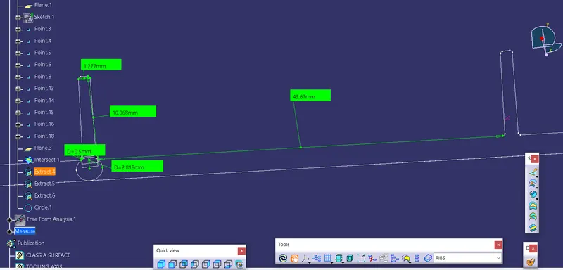
DEVELOPED RIB
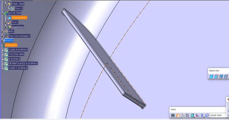
DEVELOPED RIBS
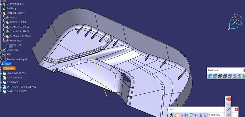
DESIGN CONSIDERATIONS FOR SCREW BOSSES
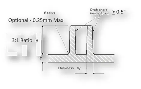
- Draft - 0.5 degrees on the walls of boss
- Thickness - Typically 40%* of the nominal wall at the base.
- Height to Diameter Ratio - 3:1
- Radii - 0.25mm maximum radii.
DEVELOPED SCREW BOSS
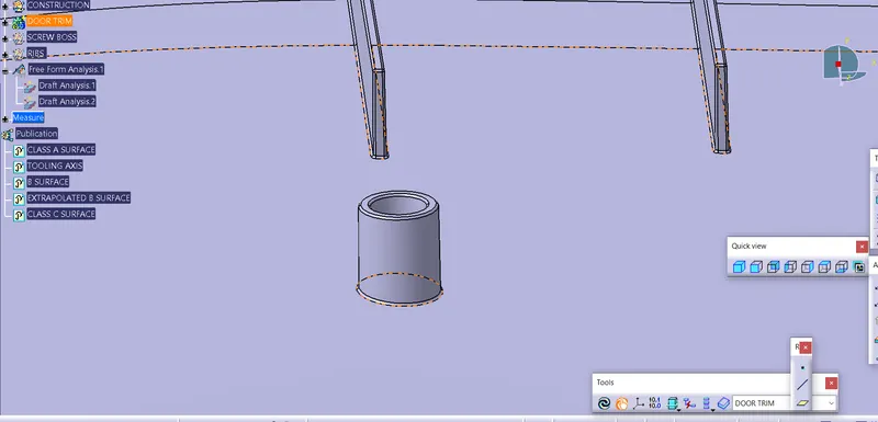
DESIGN VERIFICATION
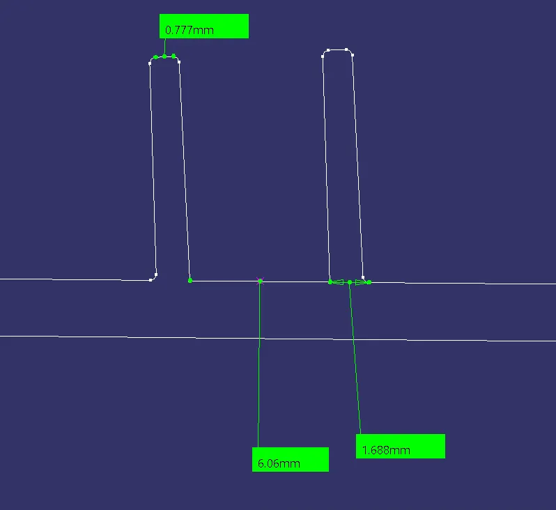
DEVELOPED SCREW BOSS
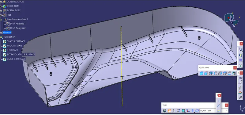
DRAFT ANALYSIS ON RIBS AND SCREW BOSS
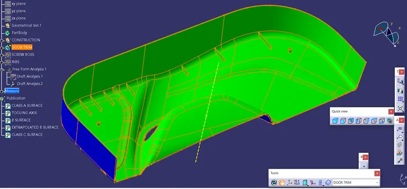
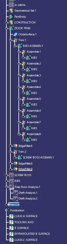
DESIGN TREE STRUCTURE FOR RIBS AND SCREW BOSSES
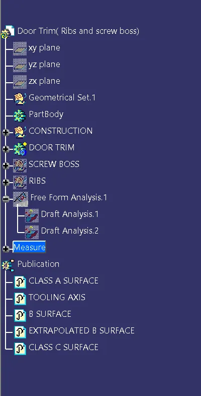
DESIGN TREE STRUCTURE FOR RIBS AND SCREW BOSSES
HEAT STAKES DESIGN
- Heat Staking is a pulsed-heat process to join two or more parts out of which one at least is made of plastic.
- The process is to deform the plastic material using heat and force at a set process time.
- The bond is made by partially de-forming the plastic part in order to fix the other.
- Heat Staking makes it easy to bond metal to plastic and is commonly used in high volume/low cost applications such as automotive, IT and consumer appliances.
- Similar and dissimilar materials may be joined: metal to metal, plastic to plastic, metal to plastic
- Accurate control operating within a small process window
- Local heating resulting in no damage to surrounding materials
- Processing of glass-filled materials
- No mechanical vibration
- Many heat-stake shapes possible through custom designed tools
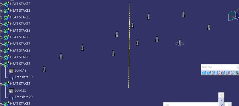
TRANSLATED HEAT STAKES
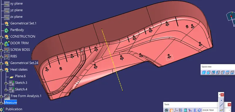
DEVELOPED HEAT STAKES IN THE LOWER TRIM
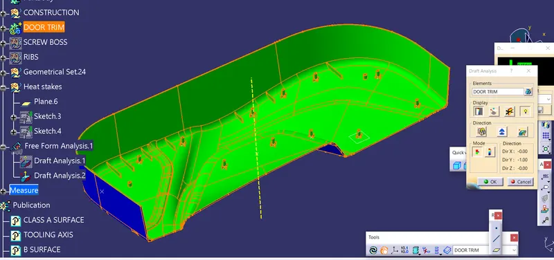
DRAFT ANALYSIS OF HEAT STAKES
LOCATORS DESIGN
- Locators are the supporting member.
- Minimum 2 locators are required for the plasic design.
- 4 way and 2 way locators are available.
- 4 way locators which arrests the 4 degrees of freedom by four ribs junctional together.
- Locators height should be higher than heat stakes.
CREATED 4 WAY LOCATOR
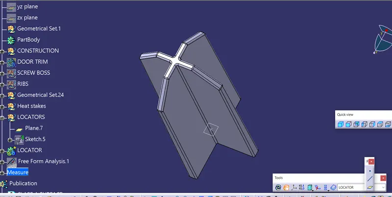
DEVELOPED LOCATOR IN THE LOWER TRIM
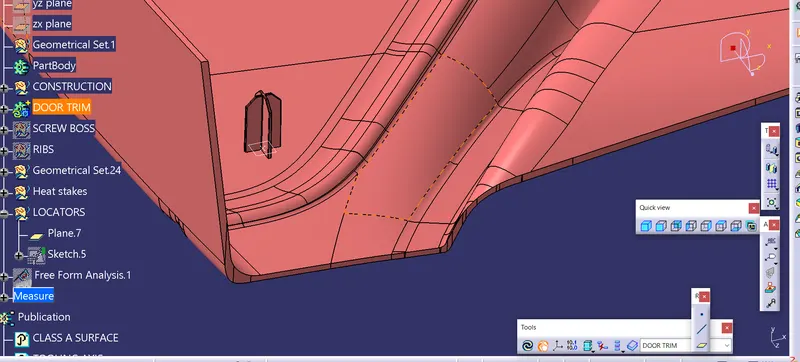
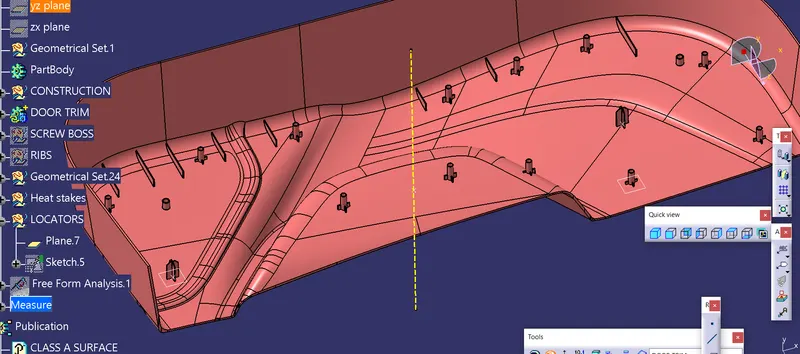
DEVELOPED LOCATOR AND HEAT STAKES IN THE LOWER TRIM
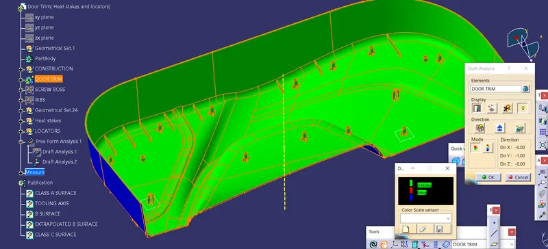
FINAL DRAFT ANALYSIS OF LOCATOR AND HEAT STAKES
DESIGN TREE STRUCTURE FOR HEAT STAKES AND LOCATORS
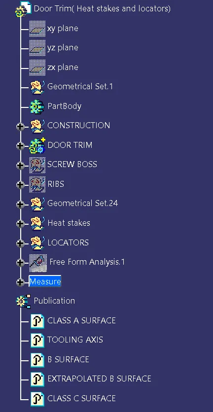
DESIGN TREE STRUCTURE FOR HEAT STAKES AND LOCATORS
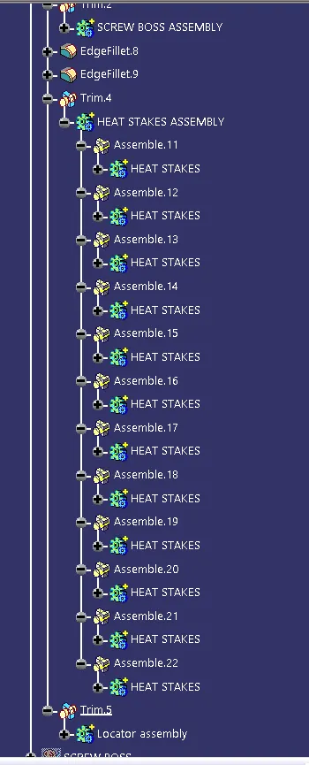
DESIGN TREE STRUCTURE FOR HEAT STAKES AND LOCATORS
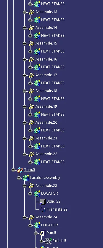
DOG HOUSE CREATION
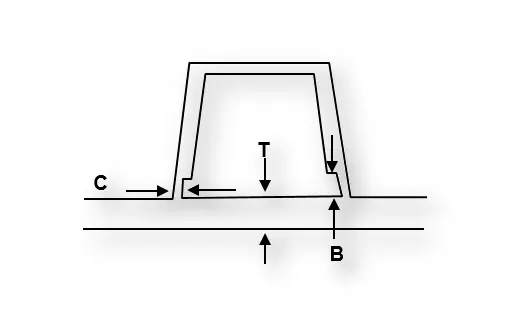
- Dog houses are designed to avoid SINK MARK created on the CLASS-A surface by screw bosses and to solve the length issues when giving screw bosses which need to be assembled to other components.
- It is also useful when perpendicular screw bosses are required on the part to the tooling direction.
- C thickness should be 40% of the main wall thickness T
- Minimum width of the dog house is 12 mm.
- Height of B should be 3-6 mm
- Minimum draft for the do house degrees 5 degrees to die draw.
DRAFTED OUTSIDE WALL OF DOG HOUSE
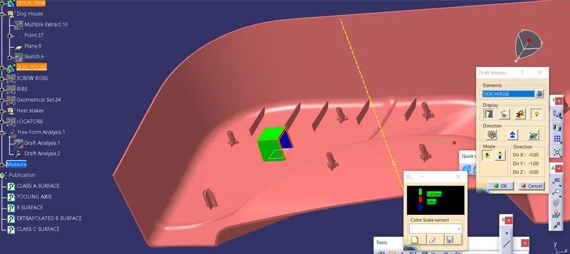
SIDE CORE AXIS CREATION FOR DOG HOUSE
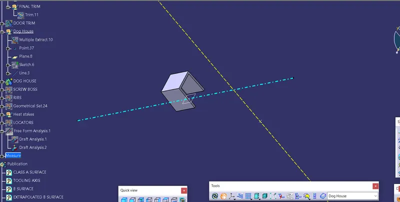
DRAFTED INSIDE WALL OF DOG HOUSE
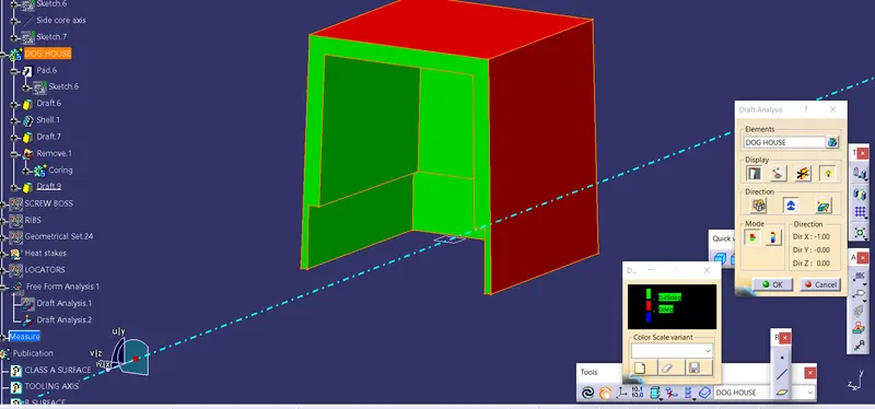
DRAFTED DOG HOUSE AFTER FILLETING
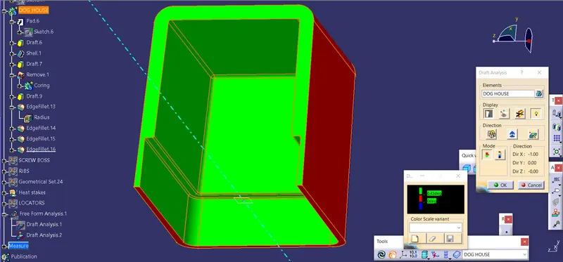
CREATED DOG HOUSE
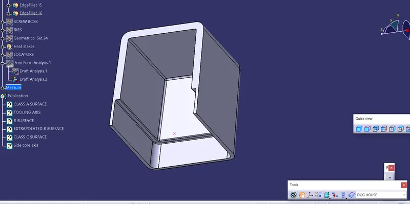
DOG HOUSE IN DOOR TRIM MODEL
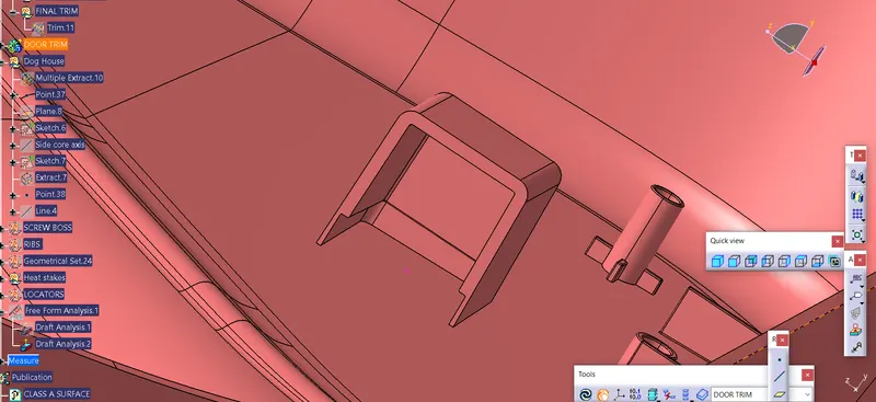
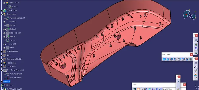
DOOR TRIM MODEL WITH ENGINEERING FEATURES
DRAFT ANALYSIS OF FINAL MODEL
DESIGN TREE STRUCTURE FOR DOG HOUSE
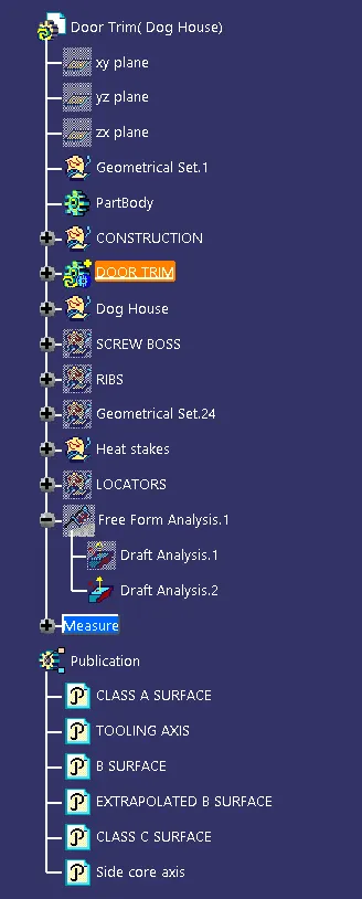
DESIGN TREE STRUCTURE FOR DOG HOUSE
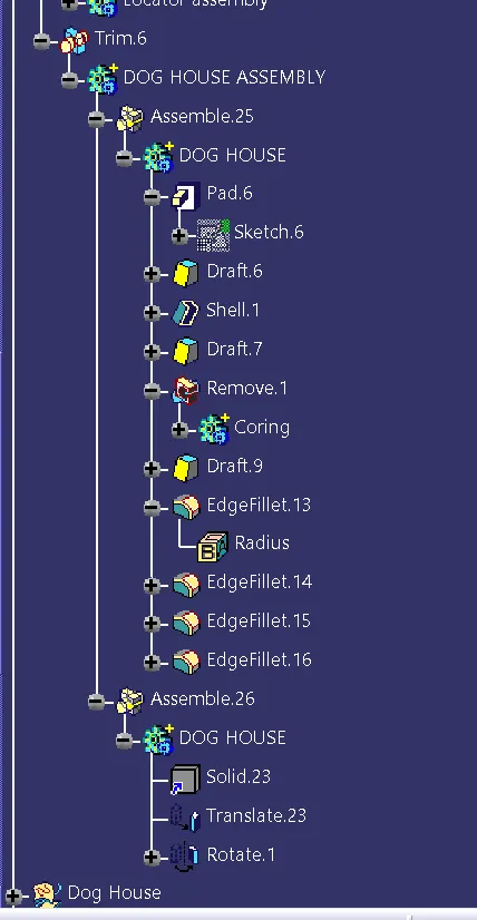
CONCLUSIONS
- Successfully created Door trim plastic component.
- Successfully performed draft analysis for class a surface and solid close surface.
- Successfully Extracted closed solid body from plastic surface.
- Created the ribs and Screw bosses for the Door Trim Lower considering the design rules.
- Created the Heat stakes and locators for the Door Trim Lower considering the design rules.
- Created the Dog house for the Door Trim Lower considering the design rules.