Week 10 - Challenge 3 - Door Trim Lower with Engineering Features
Aim:
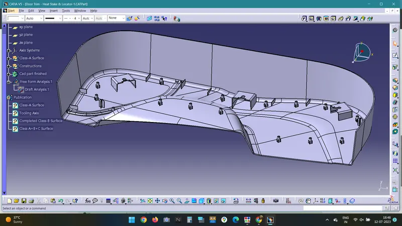
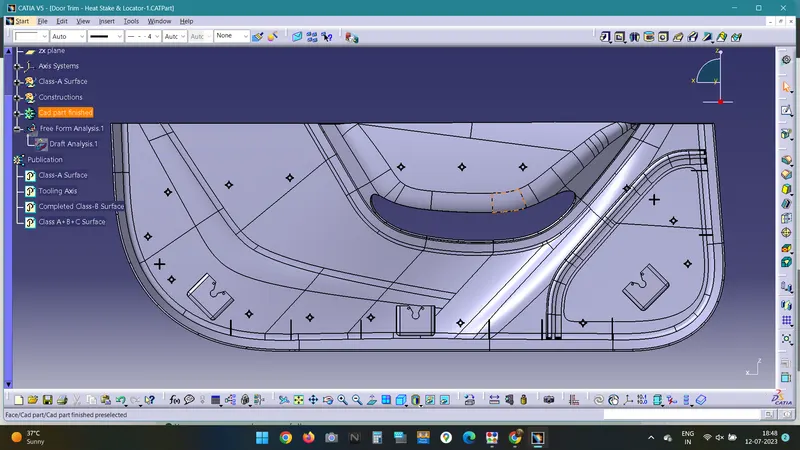
To create the door trim lower features of a plastic component through the given class-A surface by creating heat stakes and the locators considering the standard design rules.
Procedure:
Creation of Tooling Axis:
- The given class-A surface is examined at different axis for the creation of tooling axis in suitable direction.
- From the given class-A surface, it is observed that the Y-direction is the suitable direction for creating the tooling axis.
- A point is created on one of the curves of the class-a surface using point command.
- The tooling axis is created using line command using point-direction type in the y-direction.
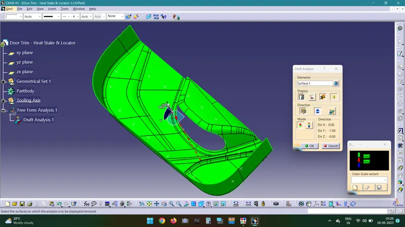
Feature Draft Analysis:
- By clicking on Insert>Analysis>Feature Draft Analysis, draft analysis dialog box appears.
- Compass is activated using compass button and made to coincided on the tooling axis and locked and draft analysis is carried on.
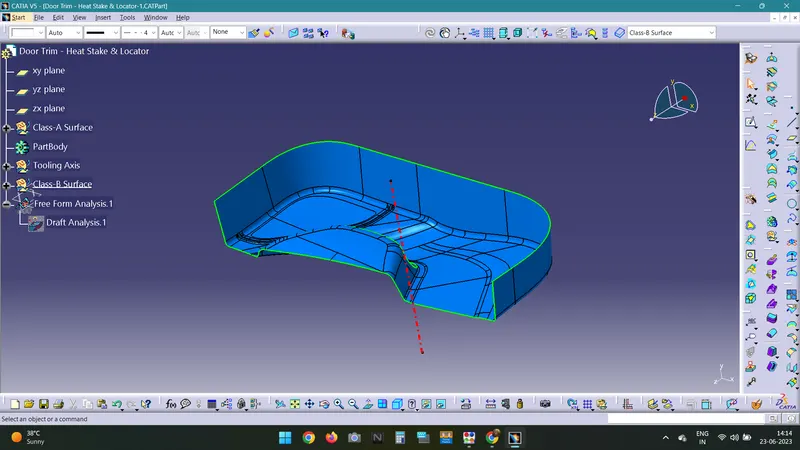
Creating Class-B Surface:
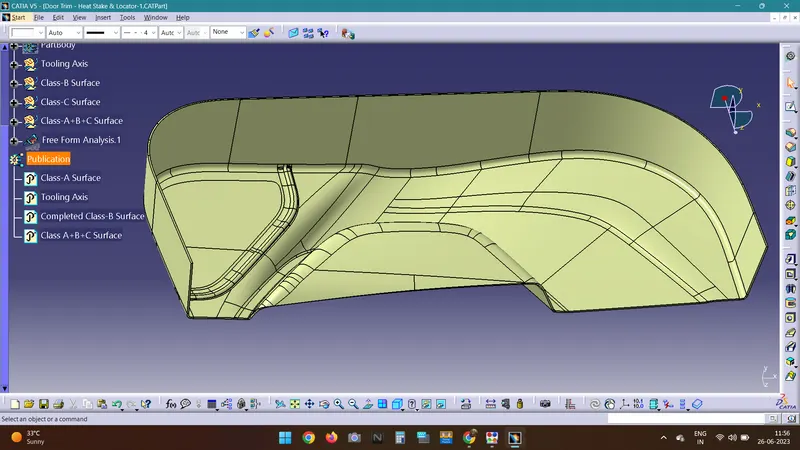
- The given class-A surface is offsetted to the required thickness i.e., 2.5 mm using the offset command and thus class-B surface is obtained with patches and gaps.
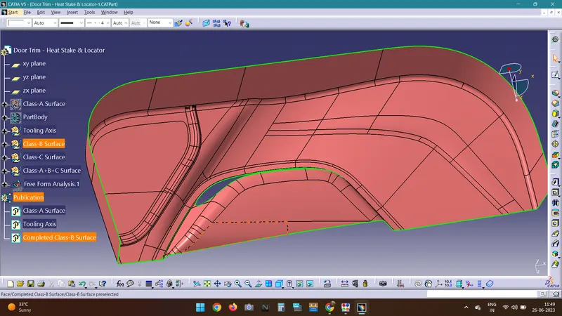
- The patches and gaps are closed using various commands such as extract,extrapolate,fill,join and trim commands.
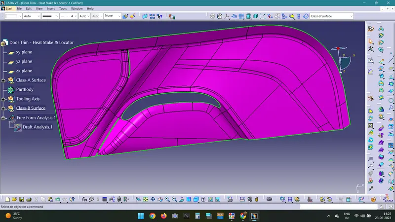
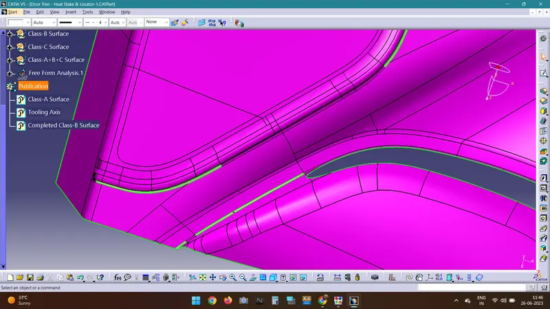
The finished class-B Surface is given below,
Creation of Class-C Surface:
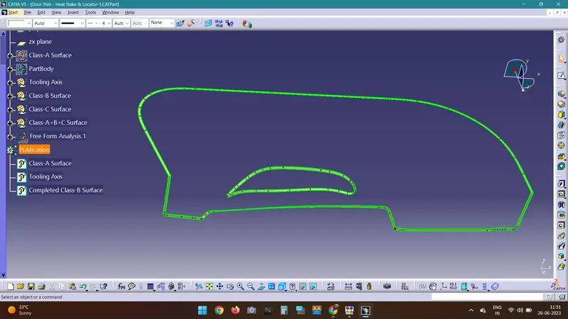
- The Class-C surface is created by extracting the boundary of class-A surface using boundary command.
- The extracted boundary is swept using sweep command for a draft of 93 degree and thus Class-C surface is obtained.
Creating Class-A+B+C surfacde:
- The Class-A and Class-C surfaces are extrapolated using boundary definition and trimmed to obtain class-A+C surface.
- Similarly the Class-B surface is extrapolated and trimmed with Class-A+C surface and forms Class-A+B+C surface as output.
Creating Cad Part Model:
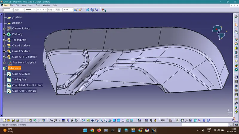
- The Part design workbench is opened by selecting Start>Mechanical Design>Part Design.
- Using Close Surface feature, the final output surface is converted into cad model.
Creation Of Locators:
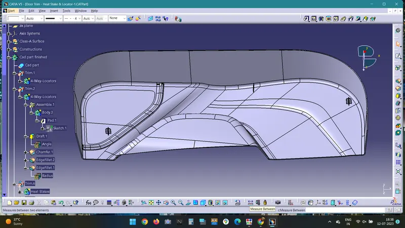
- A sketch of 4 way locators is drawn as per the design standards and made to solid using pad command and with a draft degree of 0.5 degrees and fillet of 0.25 mm and entry level chamfer of 3mm.
- After the completion of pad work ,the locators are translated using translate command to different required locations.
- Then the locators are trimmed with the final cat part.
Creation of Heat Stakes:
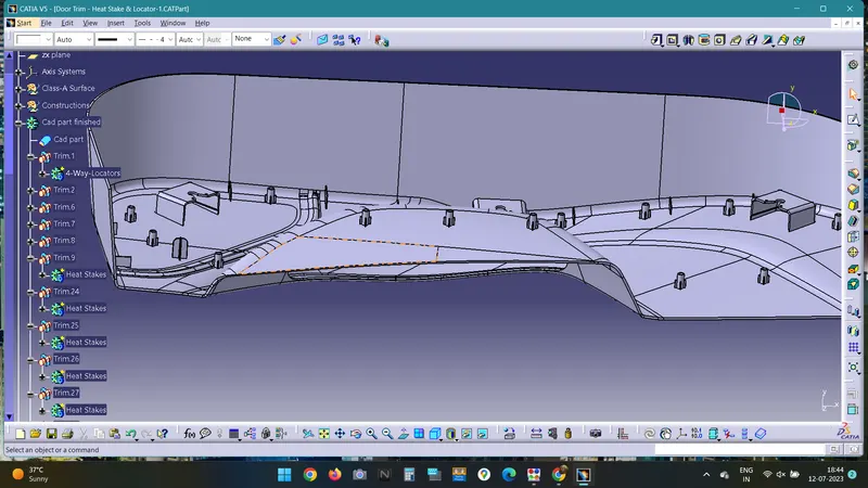
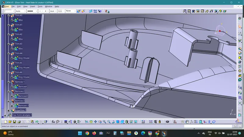
- Similar to the locators ,a sketch is drawn with two circles of diameter 7 and 5 respectively and then padded to the required height.
- Ribs are created as a support to heat stakes at lower height and then trimmed.
- Then the heat stakes are translated for the required numbers.
- Then all the heat stakes are trimmed with final cad part.
Creation of Ribs :
- As per the given requirements , ribs are sketched,padded and then trimmed with the final cad part.
Creation Of Dog House:
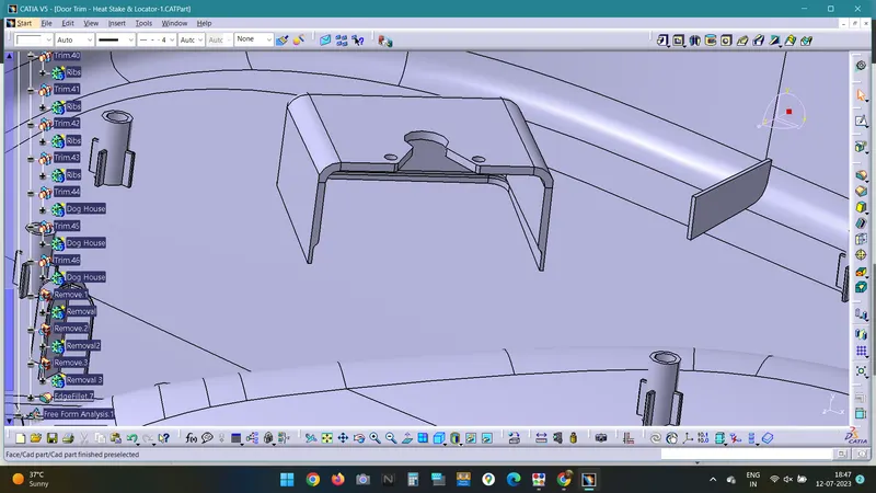
- The sketch for dog house is drawn at the requied place using positioned sketch.
- The sketch is filleted and converted using thick surface command into solid.
- The bottom removal portion is obtained using extract,offset,extrapolate,split commands.
- The top removal portion is sketched ,padded and removed from the dog house.
- The final dog house structure is translated and rotated as per the requirements.
- Then the dog house feature is trimmed with the final cad part.
Final Finished Surface: