Week 10 - Challenge 3 - Door Trim Lower with Engineering Features
Aim : Create the Heat Stakes and the locators considering the design rules for the door trim planer
Objective : to understand how to create locators and heat stake also theire importants .
Details Explations of creation of heat stake and locators :
in this challenge we get the door trim class a surface and using that we create b surface and c surface than close surface used that we get solid object than we create locator as well as heat stake
class A surface :
given in the challegen
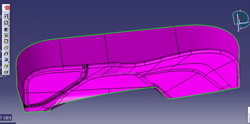
use this class A surface we create tooling axis for draft anaiysis for fulfill the the requirement
Tooling axis :
we create tooling axis for given class a surface in that we 1st create on point where is tooling axis place in direction y axis so we 1st get point so we select the plane surface on a surface and extract than create point on surface than follow above process and create line than rename this point name is tooling axis
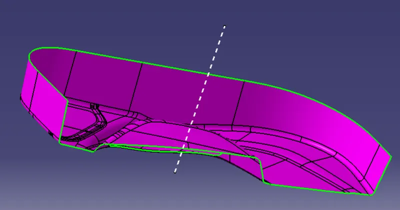
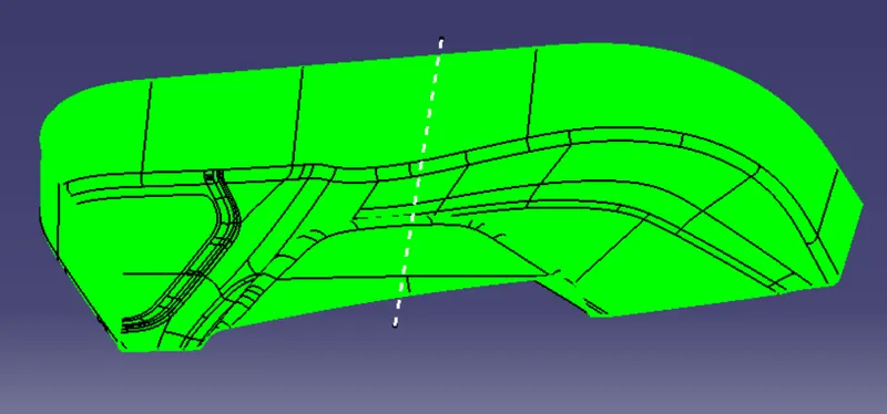
than we check the tooling axis is right or wrong by draft analysis of class a surface and get the whole class a surface is green so your tooling axis is right
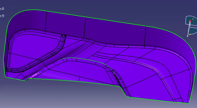
B surface :
we offeset the class a for 2.5mm
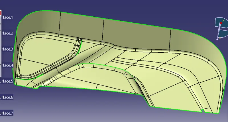
in offset some part not offset properly so we fixed it by using mater section command and get final B surface
C surface :
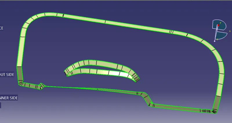
here c surface used to close surface so we used class a surface and create the c surface c surface create by using sweep command with reference to the boundary of class a surface each section than join in single surface by using join command
Close Surface :
here we join the class a and c surface
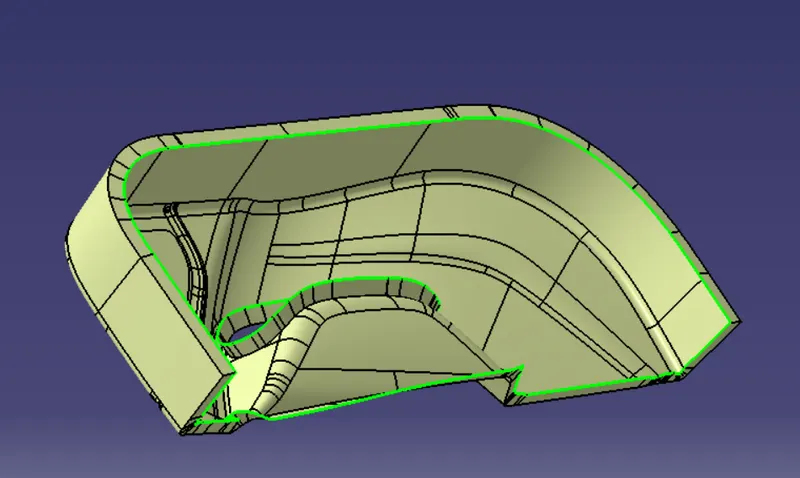
than we trim this output that is class a n c surface with b surfeace we get final close surface
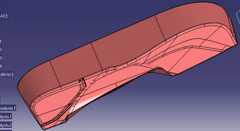
than we get solid stage by goto partdesign in that close surface option we get final close surface
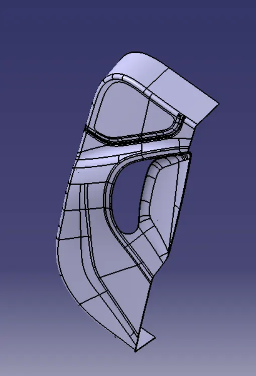
than we done draft analysis for check this draft angle right or wrong
now we goto design of heat stake and locator
Design of heat stake and locator :
Locator Design :
1st we create point on object where is we placed the locator than use this point we create a plane use the plane and point we for sketch and we sketch the four way locator after drawing locator we pad it this drawing for desired size by inserting new body than we draft on loctor as refernce of the tooling axis than fillet it than we translate this loctor by using transalte command in than poin to point option we creat varoius locatoe for desired place in that we help point which has alredy given the class a surface than we untrim it the locator body with main body this done step wise than we goto design of heat stake
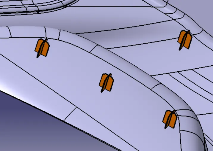
Heat Stake Design :
here is same as locator design create plane as per mention on locator design than we sketch the heat stake draw two circle 5 mm and 7mm than pad it with other body by using insert new body than draft it desired angle than copy the entire body and main parent for new heat stake for locate point by using transalet command as same as locator step than assmeble one body all heat stake than union trim with main body
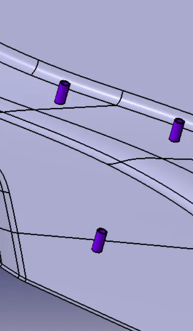
than we get final object so than we goto draft analysis
Draft Analysis :
here is final analysis of draft for final part with refernce tooling axis which is create as direction of injection mould jet direction for easy to moulding of part
here we analysis the part
The minimum feasible draft angle for this design is 3 degrees. Generally for plastic components, a minimum draft angle that can be achieved is 0.5 degrees
Go to the Insert menu and select the Analysis option.
Select Feature Draft Analysis.
Select the Material option and select the surface.
Drag the compass and place it on the tooling axis.
click on the surface and see that the surface is within the permissible limit of the draft values.
Click on Okay.
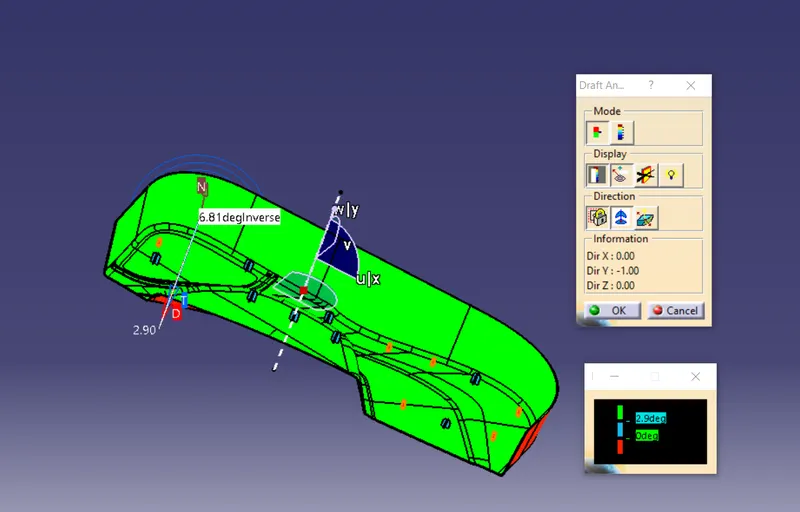
here see it green colcor meance safey and max angle is 2.9 degree and show sky color red color part not faced directly injection jet
Note : this challnge attach the catia part file in zip format for refence pls check it .