Week 10 - Challenge 3 - Door Trim Lower with Engineering Features
A vehicle door is made up of metal and plastic surface. The outer region of the door is made of sheet metal which has outer and inner panel. The surface of the door that is visible to the passenger when sitting inside the same is called inner door trim. It is made of several other trims and this particular part is the lower door trim. It consists of features that help in plummeting the drivers comfort by having different sections to hold object in place and control switches of music system and other door control operations.
HEAT STAKES through the application of heat is used combine plastic parts with other components that are made up of other materials like steel. Staking is the process to combine components made of desimilar materials. The molted plastic parts combine a projection which is melted and fills the volume of the forming tool cavity which in turn produces the head to lock the other part.
The protruded plastic that is there on the base part is allowed to fit into a hole of the other part of other material. The protruded plastic then gets melted by exerting high pressure along with heat that turns the protruded surface into a shape as shown in the pic to lock both the parts tightly and hence the parts are joined together.
LOCATORS
A part has a total of 12 degree of freedom as shown in the pic below. A part that has to be worked upon on a tooling workbench for machining or welding should be fixed to restrict all the 11 d.o.f. mentioned the movements.
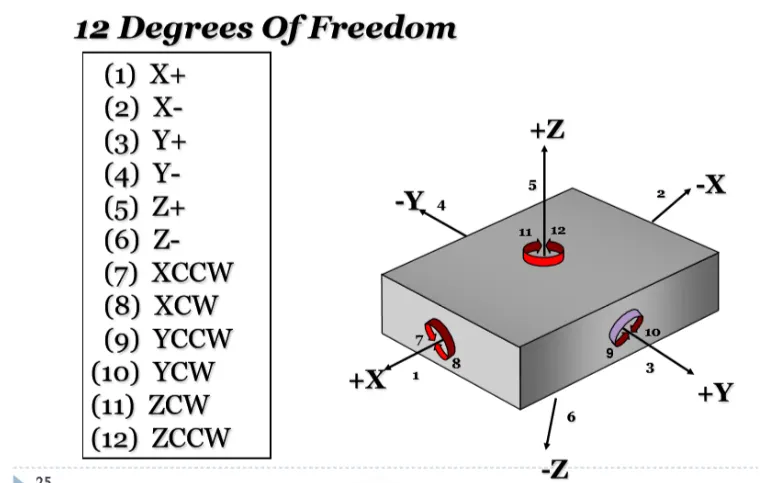
A component or part usually has several such locators that helps in perfect fixing of the same onto another one and holds it while the component goes through several stress applications. There are two types of locators which are 2-way and 4-way locators. A 2 way locator restricts less degree of freedom than a 4 way locator.
DESIGN OF THE PART IN CATIA V5
The same design technique was used to create this part in which a class A surface was given and with the same, class B and C surface were created and then joined together.
*) Class A surface was already given so by creating the boundary, the whole outline of the body was obtained to study the surface quality of the surface which was OK as there were no discontinuity in the boundary and was neat. So the same surface can be referred to create the other surfaces.
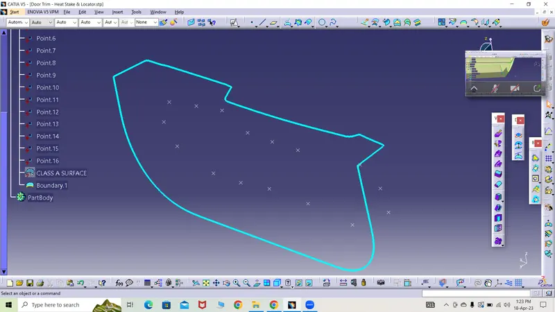
*) A geometrical set with the name tooling axis was created.
*) The surface was observed in different views. The surface with large surface area visible when seeing from tooling axis has to be considered for a proper manufacturing of the final part.
Front view
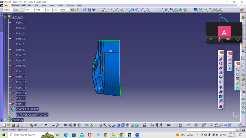
Side view
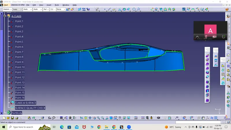
Top view
Top view allowed the maximum surface area to be visible while viewing and so this view was finalized for creation of the tooling axis.
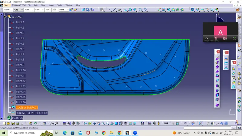
*) There are 3 methods to create the tooling axis. The first one is the normal to surface method.
*) A flat surface was extracted and then a point was created on it. The option of line creation was selected and normal to surface option a line was created and later draft analysis was done.
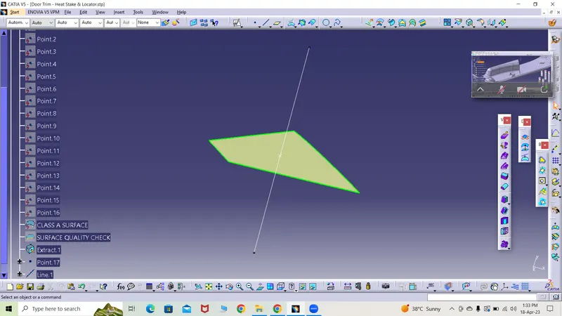
Draft analysis of CLASS A surface with normal to surface line as tooling axis
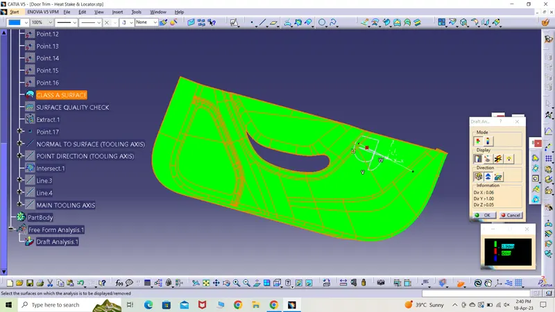
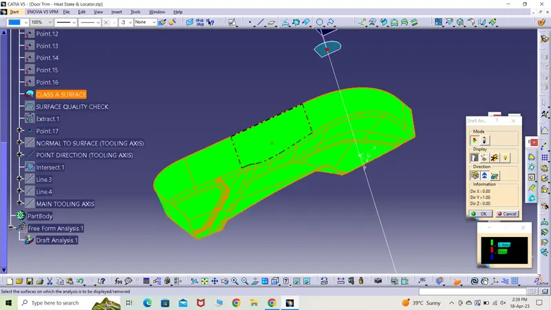
*) The second method is creating line in a specific direction.
*) The same point was considered to create the line by choosing the y-axis in direction and a line was created and later draft analysis was carried.
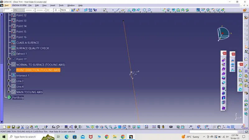
Draft analysis of CLASS A surface with point direction line as tooling axis
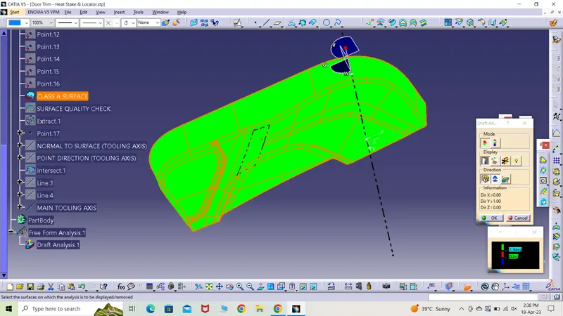
*) Third method is the line bisecting.
*) The intersection of class A was taking a reference with the correct plane. The boundary was created.
*) Taking the two end as reference, two lines were created with the help of the points.
*) A line was created by using line bisector option and the given point. This line was considered as the main tooling axis.
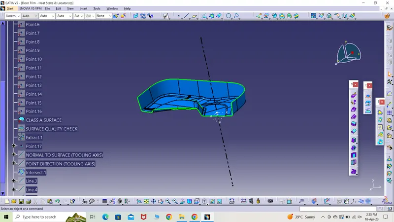
Draft analysis using line bisector as tooling axis
CLASS B SURFACE CREATION
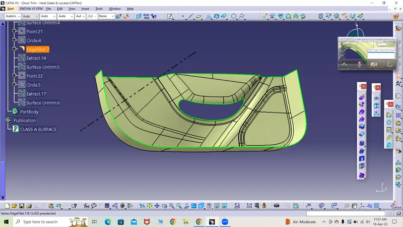
*) The part was offsetted towards inside to 2.5mm which is the desired thickness of the final part.
*) There were some regions with gaps in between which was highlighted with the open surface colour i.e. green.
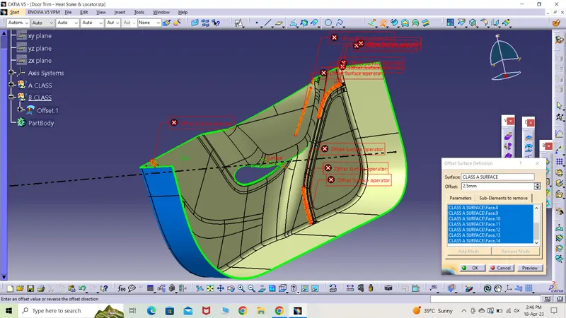
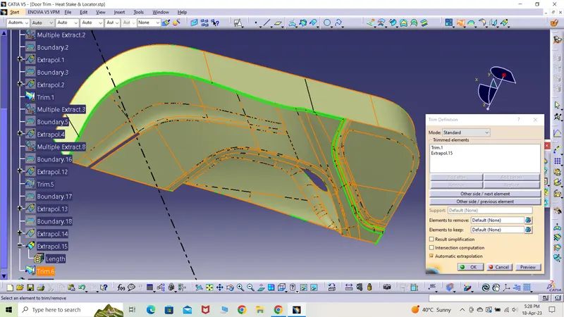
*) The gaps were extracted and expolated to intersect with the adjacent edges and later were trimmed together.
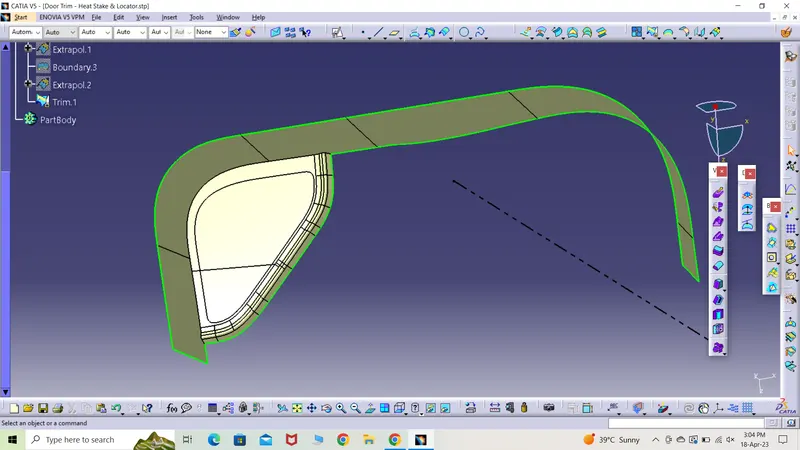
*) There were total 3 surfaces that were extracted or muti-extracted accordingly to create the surface.
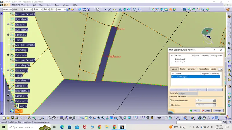
*) One gap was repaired by using multi-section surface creation option.
*) Final class B surface was obtained by giving necessary fillets to the regions with sharp edges.
CLASS C SURFACE CREATION
*) The edges were selected one by one and were created by using swept definition command to generate the sides.
*) The hollow part was created into a solid one by switching to part design mode and later selecting close surface option and the above surface as body. The solid part was created.
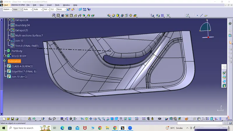
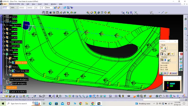
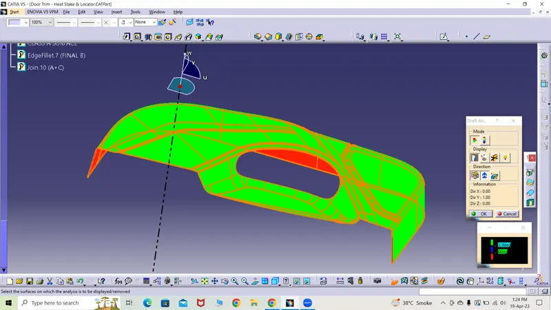
*) Draft analysis was carried out on the solid body and the result has been attached below.
HEAT STAKES CREATION
*) Heat stake was created by creating a plane parallel to any of the given point which was used as reference to create the sketch.
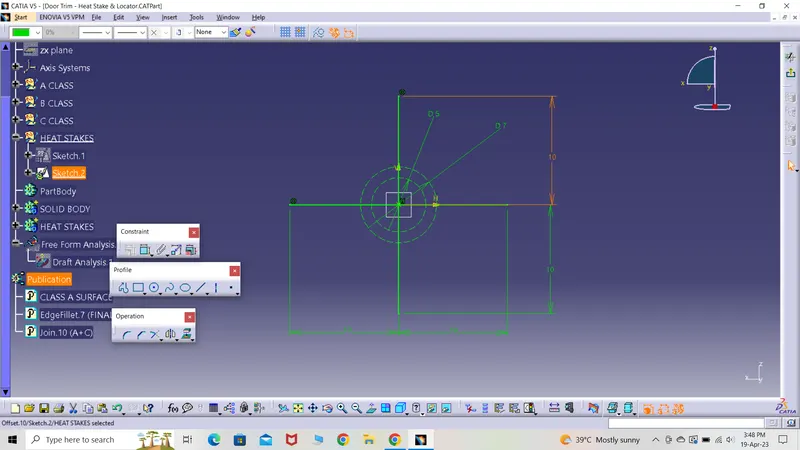
*) The diameter were taken as 8.2 and 5.2mm and iso-constrainted it.
*) Switching to the part design, padding of the same sketch was done to 18mm. Draft and fillet of value 0.5 degree and 0.25mm resp were given to the same.
*) To strenghten the heat stake, 4 way rib was given of height 15mm, draft 0.5 degree and thickness 1mm.
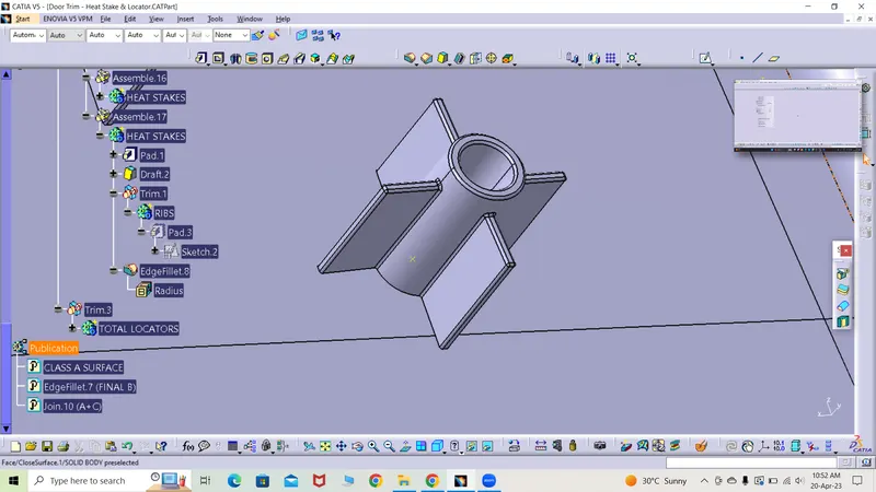
*) The same part was copied at the given points location to create the remaining stakes.
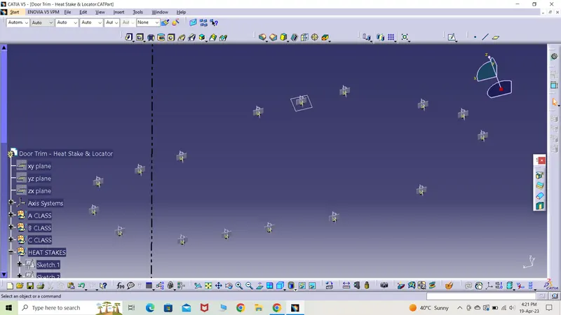
LOCATORS CREATION
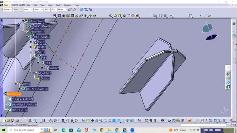
*) A plane was created in the same manner as mentioned earlier and a sketch was created as per the profile of the locator.
*) It was then padded to the length of 25mm and 1.2mm thick and tooling axis was chosen as the direction of the pad.
*) It was drafted, chamfered and filleted to 0.5 degree, 5mm 45 degree, 0.25mm values resp.
*) The same profile was copied to the other point location.
*) In the end, the ribs were created and finally all the components were joined with the solid body by boolean operation.
Complete part in different views
ISOMETRIC VIEW
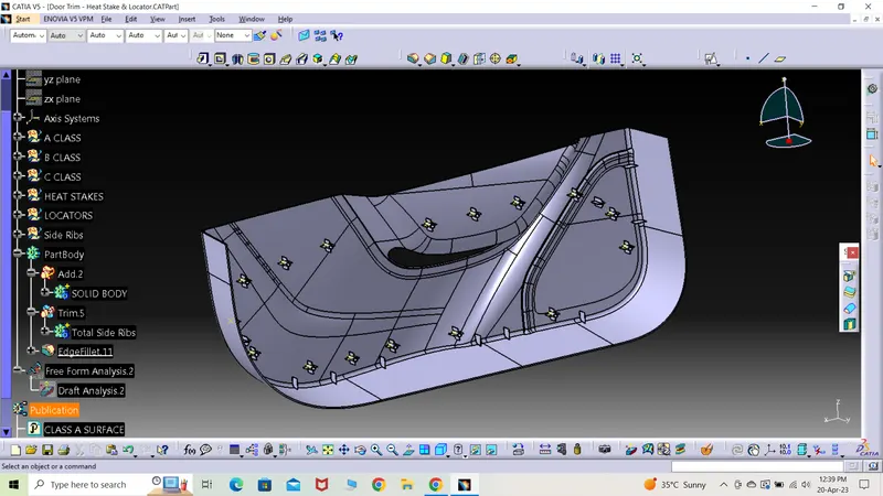
SIDE VIEW
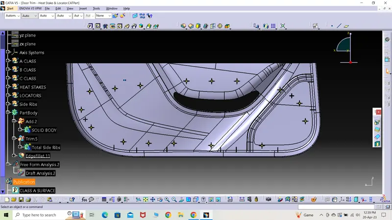
TOP VIEW
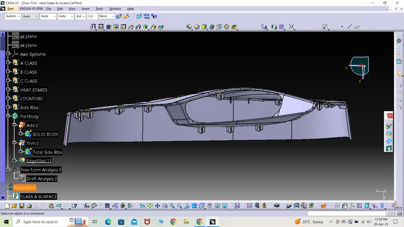
FRONT VIEW
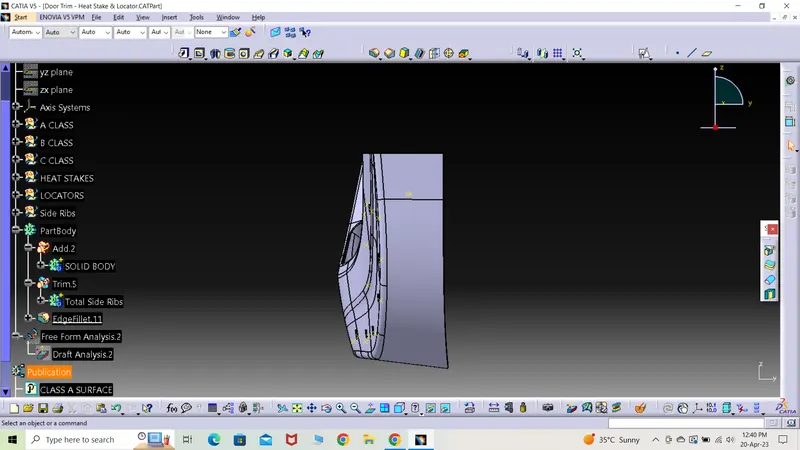
FINAL DRAFT ANALYSIS OF THE COMPLETE PART